Dynamics of Rotor Drop on New Type Catcher Bearing*
2014-04-24JinChaowu金超武ZhuYili朱益利XuLongxiang徐龙祥JiangLei蒋磊ZhouLaishui周来水
Jin Chaowu(金超武),Zhu Yili(朱益利),Xu Longxiang(徐龙祥) Jiang Lei(蒋磊),Zhou Laishui(周来水)
1.College of Mechanical and Electrical Engineering,Nanjing University of Aeronautics and Astronautics,Nanjing,210016,P.R.China;2.College of Electronic Information and Electrical Engineering,Changzhou Institute of Technology,Changzhou,213022,P.R.China
1 Introduction
Active magnetic bearings(AMBs)have advantages over conventional mechanical bearings including the facts that they can electronically modify system dynamic properties for rotor vibration control,reduce noise,be used for vibration isolation or elimination,and provide on-line virtual balancing.Therefore,AMB is well suited for the needs of some special application,such as high speed,high precision,small volume,vacuum,high specific output power,and so on.However the catcher bearings(CBs)are necessary to protect the AMBs assembly from direct contact with the rotor.They ensure the safety of the AMB systems and support continuous and reliable operation after possible AMB failures or overloads.
Most of the researches focused on the rotor dynamic responses.Kirk et al[1]studied the effect of the support stiffness and damping by evaluating dynamic response on various rotor-support system parameters and showed an optimum damping.Sun[2]conducted numerical simulations of the rotor drop on CBs in flywheel energy storage system using a detailed CB model which includes a Hertz load-deflection relationship between mechanical contacts,the speed-and-preload-depend-ent bearing stiffness due to centrifugal force,and a Palmgren′s drag friction torque.Zhu[3]established the dynamic model of a multi-disk flexible rotor dropping on CBs before and after AMB failures using the finite element method,and examined the influences of various parameters,such as dropping position,rotor imbalance,rotational speed,support stiffness,and support damping of the CBs on the dropping dynamics.Xie and Flowers[4]numerically investigated the steady-stator behavior of rotor drop on CBs and mainly studied the effects of various parametric configurations:Rotor imbalance,support stiffness and damping.Cole et al[5]developed a deep groove CB model considering the elastic deformation of the inner race,which was modeled by a series of flexible beams.They mainly studied the impact force,the effects of bearing width as well as the ball load distributions.As the rotor and bearing protecting process is a highly nonlinear problem,each researcher has some simplification and hypothesis in simulation.Those simulation results require experimental verification.Swanson et al[6]provided the test results of rotor drops for various rotor speed,unbalance amplitude and location for the five CB configurations.Zhu[7]measured the transient responses after rotor drop in a flexible rotor,and investigated the influences of rotational speed,rotor imbalance and lubrication condition on the contact surfaces of the CB on the transient response.Qin[8]introduced auxiliary bearing used in the HTR-10GT project and presented a test rig built up for the following rotor drop test.Hawkins et al[9]presented the orbit and time-history data after a full-speed(30 000r/min)rotor drop in the cryogenic gas expander system.
The emphasis of those researches was,however,laid on the support stiffness and damping of CB.Considering the difficulty of modifying the bearing stiffness and damping,to obtain the optimum simulation results,a new type of CB which has two separate rolling element series is proposed in this paper.On one hand,this new type of CB possesses higher limit speed as a result of the share speed of the intermediate race,which makes it capable of withstanding higher rotor initial rotating speed.On the other hand,the new type of CB has one more bearing compared with the traditional CBs,which brings it the advantage of buffering rotor vibrations after rotor drop.The above advantages of DDCB have been verified by both simulations and experiments.
2 Simulation
2.1 Structure of AMB
Fig.1shows the studied structure of a motor drive system equipped with magnetic bearings.The motor is located between the two radial magnetic bearings.Each radial magnetic bearing generates radial forces in two perpendicular radial axes.Thrust magnetic bearings regulate the axial forces in the shaft direction.All the magnetic forces are controlled by negative feedback control systems so that the rotor is regulated to the center of the stator bore.Besides those magnetic bearings,two catcher bearings are located in the two ends of the structure respectively to prevent damages in the event of a component,power or a control loop failure or overloads.The air gap between the catcher bearing inner race and the rotor is half of the air gap of AMB.The outer race of the catcher bearings are rigidly mounted to the bearing housings which are also rigidly mounted to the ground.

Fig.1 Structure of AMB system
2.2 Structure of CBs
In order to improve the limit speed of the CB,two deep groove ball bearings(61801)are mounted together to constitute the first layer of DDCB,while a deep groove ball bearing(61805)acts as the second layer that is mounted in the bearing housing.The new type of CB is the combination of those three bearings.The formed three races are denoted as inner race,intermediate race and outer race,respectively.The detailed structure of DDCB is shown in Fig.2(a).The structure of SDCB is also shown in Fig.2(b).

Fig.2 Structures of DDCB and SDCB
2.3 MSC.ADAMS model
Multi-body dynamics simulation software MSC.ADAMS is used to simulate the rotor drop process[10].
According to the rotor parameters,rotor model shown in Fig.3is established using ADMAS,where Lais the distance between AMB and rotor barycenter;Lbis the distance between CB and rotor barycenter;Lsis the distance between displacement sensor and rotor barycenter;Lcis the length of AMB rotor;and Ldis the length of motor rotor.The relevant parameters of rotor are listed in Table 1.
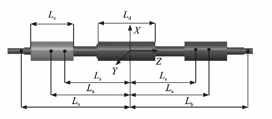
Fig.3 Rotor structure ADAMS model

Table 1 Relevant parameters of rotor
Impact function and recovery coefficient are the two main methods for defining the contact in ADAMS.Usually,the use of impact function is wider and more accurate.Contact stiffness k and damping c are used to calculate the crash force in this rotor drop model.
Fig.4shows the contact model between rotor and inner race,and the impact function can be expressed as a subsection function


Fig.4 Contact model between rotor and inner race
where sis the relative displacement between rotor and inner bearing;s0=R-r,here Ris the bore radius of inner race and rthe radius of rotor;eis the contact coefficient,and for point contact e=3/2and line contact e=10/9;cmis the maximum damping coefficient;dmis the distance when the damping ratio reaches the maximum,and dm=0.01mm;STEP function is used to keep the contact damping continuous,s is the variable of the STEP function,s0-dmis the initial value of variable and s0is the final value of variable;and kis

where Lis the contact length.
Stiffness-damping contact model is also adopted to define the catcher bearing internal contacts.Based on Hertz theory[11],the contact stiffness between ball and race can be calculated using the bearing geometrical and material parameters.

where eδis the Hertz contact coefficient associated with the contact surface curvature,and can be calculated by Ref.[12]interpolation;ρis the contact surface curvature.
As there is no reliable theoretical method for calculating the bearing damping,empirical values are chosen in this paper.The relevant parameters of bearing are listed in Table 2.
In order to simplify the modeling process,two separate models of inner and outer bearings are merged together in ADAMS as shown in Fig.5.The use of this method realizes the model establishments of rotor drops on DDCB and SDCB synchronously.
For the whole CB model,constraint relationship between each part of the bearing is divided into three kinds:(1)The outer race and ground are set as a fixed side,so that the CB is fixed on the ground;(2)the bearing rolling body,the inner channel,and the outer channel and cage are set as contact pair;(3)the inner race and rotor are set as contact pair.
The initial motion state of rotor is indispensable to carry out the rotor drop simulation.Rigid rotor model is established to analyze the dynamic responses,and the motion formulas before rotor drop can be expressed as follow

where Mis the rotor mass matrix;Xois the displacement vector of rotor barycenter;Gis the rotor gyro torque matrix;Ais the introduced parameter matrix;Faand Fbare electromagnetic force and centrifugal force matrices respectively.
The displacement vector Xoof the rotor barycenter can be expressed using the rotor displacement vector Xcat the two ends of radial sensors.

Table 2 Relevant parameters of double-decker catcher bearing
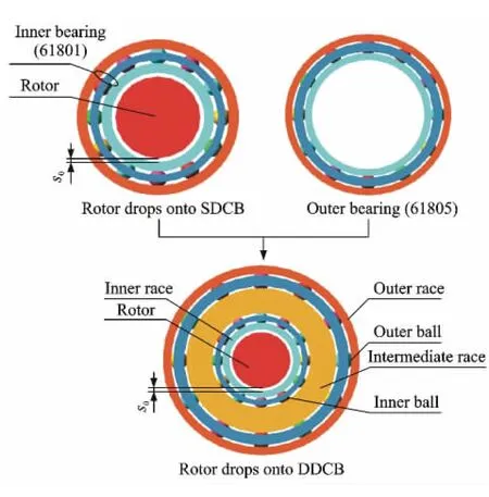
Fig.5 Model of rotor drop in catcher bearings

The rotor motion Eq.(4)can be rewritten as

The AMB parameters are:Pore area A=1.96×10⁻⁴m2;linear amplifier power gain GA=0.4A/V;linear sensor gain GS=20 000V/m;bias current I0=2A;numbers of the coils N=130;gap of the rotor at balance position x0=0.25×10⁻³m.The AMB controller is a PID controller,and the transfer function is

where proportional coefficient kp=2.3;integral coefficient ki=10;differential coefficient kd=1.4×10⁻³;and filtering time constantτd=7×10⁻⁵.
The detailed modeling of rotor dynamical models before failure of AMBs and support model of AMBs can refer to Ref.[13].So the rotor vibration characteristics before rotor drop are obtained by compiling the MATLAB calculation program.And here,the rotor initial vibration displacement is supposed to be 7μm and velocity is supposed to be 0.6m/s at the rotor initial rotating frequency 200Hz.The initial angle between the velocity and the horizontal axis is 90°.
2.4 Simulation results
The orbit of the left journal for different CB types from 0to 0.2safter rotor drop is obtained by simulation,shown in Fig.6,along with the nominal catcher bearing clearance circle.Fig.6 indicates that the rotor jumping height using SDCBs is higher than that using DDCBs,and the rotor orbit using SDCBs is significantly more confusing compared with the orbit using DDCBs.Moreover,the amplitudes of rotor vibration are decreased by at least 28%after rotor drop with the help of DDCBs.
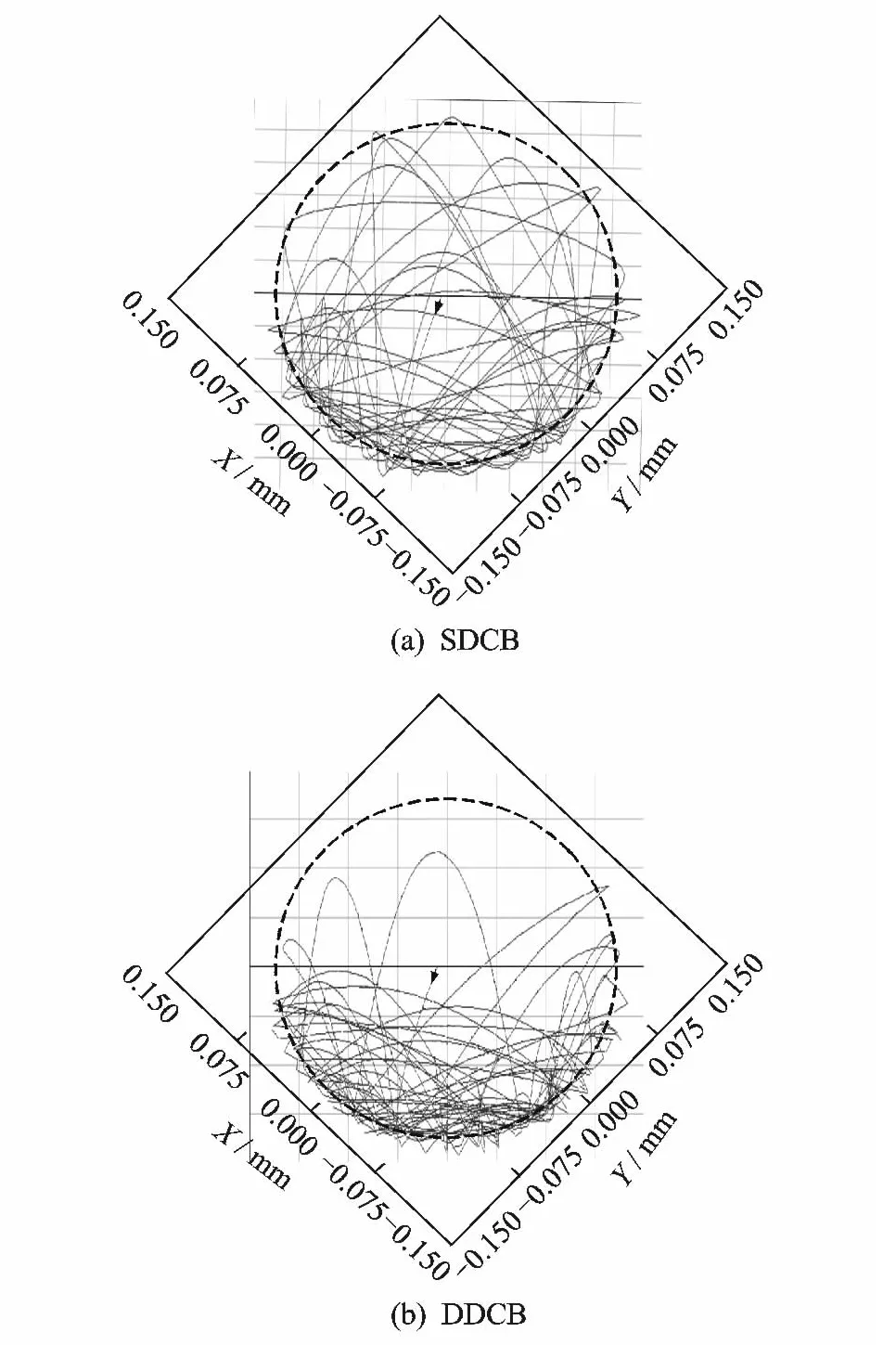
Fig.6 Orbits of left journal obtained by simulations for various CB types
Fig.7presents the contact forces Fn1between the left journal and inner race after rotor drop.The added outer rolling bearing endues DDCB with smaller support stiffness but larger damping.Due to the changes of the support characteristics,the DDCBs have a decrease about 15%—27%of the maximum contact forces compared with the simulation results using SDCBs.And the contact forces using DDCBs gradually decrease with time,but the contact forces using SDCBs are randomly distributed and not too much regularity.

Fig.7 Contact forces between left journal and inner race obtained by simulations for various CB types
3 Experiments
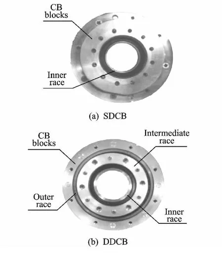
Fig.8 Photographs of CBs and CB blocks
In order to verify the simulation results and the performance of DDCB discussed above,a DDCB is fabricated.Fig.8shows the mechanical parts of DDCB,SDCB as well as the corresponding bearing blocks.The test rotor is suspended by a five-degree-of-freedom AMB system and rotated by a driving motor,as shown in Fig.1.Before and after rotor drops on different types of CBs,the dynamic characteristics of the rotor are theoretically derived in Ref.[14],whose experimental device and data are the same as that in this paper.
The experimental facilities necessary for measurement are shown in Fig.9.The controller of AMB is analog PID controller.The parameters of the rotor,bearings and controller are similar as the simulation parameters.We use eddy current sensors to measure the displacement signal of the rotor and a fiber sensor to detect the black and white stripes painted on the rotor.The output signal of the fiber sensor is used by a rotor drop control board to calculate the rotor spin velocity and phase.This control board can also switch off the power transistors of AMB electric control system when the rotor is in the specified initial velocity and phase states to guarantee that the rotor drop on different types of catcher bearings in the same initial motion state.The system adopts two fiber sensors to quantify the rotating speeds of the inner and intermediate races and uses a converter to supply the motor in the AMB with a rotational torque.All the sensor signals are collected by the data collection card and stored in the computer.For the data acquisition,three boards NI-9215 from National Instruments are chosen.MATLAB software is adopted to carry out the subsequent analysis of the acquired data.

Fig.9 Photograph of experimental facilities
Figs.10(a,b)present the orbits of the left journal after rotor drop at the rotor initial rotating frequency 200Hz obtained by experiments.It can be seen from Fig.10that,the rotor drops on the CBs and bounces several times on the inner race when the AMB system becomes inactive.The rebound height and times using DDCBs are smaller than that using SDCBs.Comparing Fig.6and Fig.10,the experimental results are basically correspondent with the simulation results and verify the correctness of simulation models established using multi-body dynamics simulation software MSC.ADAMS.
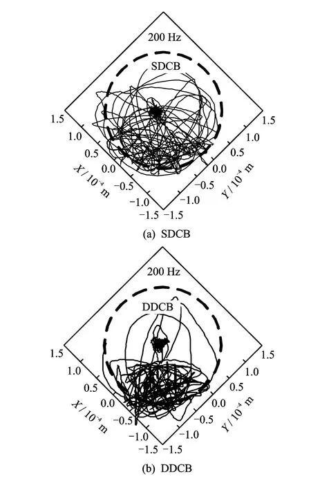
Fig.10 Orbits of left journal obtained by experiments for various CB types
Fig.11shows the frequencies of different rotating parts obtained by rotor drop experiment,which can give us a better understanding of the dynamical behavior of DDCBs and SDCBs.The speed of inner race can be distributed to the intermediate race according to a certain ratio using DDCBs.Speed distribution rate is not very high,only 17%.The reason may be related to internal and external bearing pitch diameter ratio,lubrica-tion and lubricant viscosity and will be studied in other papers.As the contact forces between the rotor and the CBs are complex and not easy to get,the change of contact forces needs to be reflected by measuring other parameters.When the contact forces change,it will cause the friction between the rotor and inner race changes.Because the friction serves to reduce the rotational speed of rotor,the rotor speed changes will be accelerated when the contact forces increase.The contact force changes could be obtained by analyzing the rotor speed changes.Fig.11indicates that the rotor speed changes using DDCBs are smaller,compared with the changes using SDCBs.The contact forces reflected from the side will decrease by using DDCBs.

Fig.11 Rotating frequencies of rotor,inner race and intermediate race obtained by experiments
4 Conclusions
In this paper,DDCBs are proposed to be used as CBs in AMB system.The dynamic responses of the rotor drops on DDCBs and SDCBs are respectively simulated on the platform of ADAMS.Finally,rotor drop experiments are carried out to validate the simulation results.The following conclusions can be obtained from the above researches:
(1)DDCBs can help to reduce the rotor vibration amplitudes and the contact forces after rotor drop.
(2)The speed of inner race can be distributed to the intermediate race according to a certain ratio.The angular acceleration of the intermediate race is a little smaller than that of the inner race.
[1] Ishii T,Kirk R G.Transient response technique applied to active magnetic bearing machinery during rotor drop[J].Journal of Vibration and Acoustics,1996,118(2):154-163.
[2] Sun G Y,Palazzoloa A B,Provenzab A,et al.Detailed ball bearing model for magnetic suspension auxiliary service[J].Journal of Sound and Vibration,2004,269(3):933-963.
[3] Zhu Changsheng.Dynamics of rotor drop on backup bearings after active magnetic bearings failure[J].Journal of Zhejiang University:Engineering Science,2005,39(11):1173-1178.(in Chinese)
[4] Xie H,Flowers G T.Steady-state dynamic behavior of an auxiliary bearing supported rotor system[C]//American Society of Mechanical Engineers Winter Annual Meeting.Chicago,USA:Minerals,Metal &Materials Society,1994:1-11.
[5] Cole M O T,Keogh P S,Burrows C R.The dynamic behavior of a rolling element auxiliary bearing following rotor impact[J].Journal of Tribology,2002,124(2):406-413.
[6] Kirk R G,Swanson E E,Kavarana F H,et al.Rotor drop test stand for AMB rotating machinery-PartⅠ:Description of test stand and initial results[C]//Proceedings of the Fourth International Symposium on Magnetic Bearings.Zurich,Switzerland:Vdf Hochschulverlag AG an der ETH,1994:207-212.
[7] Zhu Changsheng.Experimental investigation into the transient response of a flexible rotor dropping on a back-up bearing after active magnetic bearing failure[J].Acta Aeronautica et Astronautic Sinica,2009,30(8):1537-1543.(in Chinese)
[8] Qin Q Q,Yang G J,Shi Z G,et al.Preliminary research of auxiliary bearing in HTR-10GT project[C]//Proceedings of the 16th International Conference on Nuclear Engineering.USA:American Society of Mechanical Engineers,2008:623-628.
[9] Hawkins L,Prosser D,Filatov A,et al.Test results and analytical predictions for rotor drop testing of an active magnetic bearing expander/generator[J].Journal of Engineering for Gas Turbines and Power,2007,129(2):522-529.
[10]Li Zenggang.ADAMS introductory explanation and the example[M].Beijing:National Defense Industry Press,2009.(in Chinese)
[11]Harris T A.Rolling bearing analysis[M].4th Edition.New York:John Wiley &Sons,Inc.,2001.
[12]Okamoto Junnami.The design of ball bearing calculation[M].Beijing:Mechanical Industry Press,2003.(in Chinese)
[13]Zhu Yili.Research on new type catcher bearings in active magnetic bearing system[D].Nanjing:Nanjing University of Aeronautics and Astronautics,2013.(in Chinese)
[14]Zhu Yili,Jin Chaowu,Xu Longxiang.Dynamic responses of rotor drops onto double-decker catcher bearing[J].Chinese Journal of Mechanical Engineering,2013,26(1):104-113.
杂志排行
Transactions of Nanjing University of Aeronautics and Astronautics的其它文章
- Lattice Boltzmann Flux Solver:An Efficient Approach for Numerical Simulation of Fluid Flows*
- Experimental Investigation on Flow and Heat Transfer of Jet Impingement inside a Semi-Confined Smooth Channel*
- Flapping Characteristics of 2DSubmerged Turbulent Jets in Narrow Channels*
- Critical Length of Double-Walled Carbon Nanotubes Based Oscillators*
- Identification of Time-Varying Modal Parameters for Thermo-Elastic Structure Subject to Unsteady Heating*
- Optimal Delayed Control of Nonlinear Vibration Resonances of Single Degree of Freedom System*
