Development and Prospectives of Ultra-High-Speed Grinding Technology
2014-04-24FuYucan傅玉灿YangLu杨路XuJiuhua徐九华TianLin田霖ZhaoJiayan赵家延
Fu Yucan(傅玉灿),Yang Lu(杨路),Xu Jiuhua(徐九华),2,Tian Lin(田霖),Zhao Jiayan(赵家延)
1.College of Mechanical and Electrical Engineering,Nanjing University of Aeronautics and Astronautics,Nanjing,210016,P.R.China;2.Jiangsu Key Laboratory of Precision and Micro-Manufacturing Technology,Nanjing,210016,P.R.China
1 Introduction
Ultra-high-speed grinding(UHSG)is generally considered to be an advanced grinding process.Recent years,this technology has still drawn much people′s attention due to its outstanding characteristics,which offer excellent potential for good component quality combined with high productivity[1-5].Certainly these characteristics can also be theoretically and authentically explained by the mean uncut chip thickness hcu[6-7]

where Cstatis the static density of cutting edges,vwis the workpiece speed,vsis the circumferential speed of grinding wheel,aeis the grinding infeed,and deqis the equivalent grinding wheel diameter.α,β,γare the positive exponents and k>0is a factor.
One driving factor behind the innovative technology is to increase productivity for the conventional finishing processes.Moreover,the development of grinding machine tool components such as grinding motorized spindles with high power and high rotational speed,more efficient linear motor drives,and well-performed grinding wheels,has created conditions to shorten machining times and reduce the number of machining operations while improving the machining quality.In the course of process development,UHSG in combination with preliminary machining processes close to the finished contour enables the configuration of new process sequences with high performance capabilities.
However according to the survey on the technology trends in grinding machine tool industry regarding cubic boron nitride(CBN)grinding application,Oliveira,et al[8]pointed out that only 22%in total took up UHSG with CBN,especially including just 13%of them using CBN at a cutting speed of 200m/s.Main factors(Fig.1)for this situation call for more complex machines(machine rigidity requirements,grinding power demands and improved spindle technology)with additional systems such as improved dressing,balancing and coolant systems.Certainly economical cost is also another major issue.As a matter of fact,these aspects are generally thought to be the future breakthroughs in the UHSG technology with CBN as well.
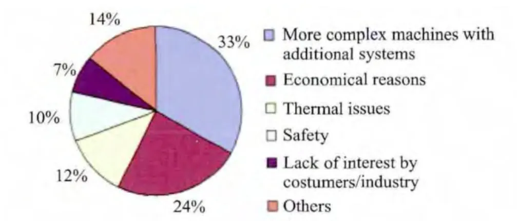
Fig.1 Reasons for not using high-speed grinding[8]
Encouragingly applying UHSG process can achieve either workpiece surface quality improvement or productivity increase,depending essentially on the characteristics and quality requirements of the workpiece to be machined.As a result,it is utmostly significant and necessary to develop reliable and higher performance UHSG machine tools and CBN wheels at low cost to conduct further investigations on UHSG technology because UHSG is so meaningful and attractive.Ultimately,it will give a more objective but persuasive scenario for the relevant researchers and decision makers in industry.
2 Basic Principle of UHSG
Grinding is a complicated abrasive cutting process attributed to a machine with geometrical-ly irregular cutting edges,in which each grain removes a chip from the surface of workpiece material and generates a surface finish.Specific deformation and chip formation in grinding process can be well represented in Fig.2.Similar to the cutting process,a typical grinding process is also constituted of three main components,i.e.rubbing,ploughing,and chip formation.Initial cutting interface is featured by elastic deformation and then plastic flow of the workpiece material.Hence,in addition to the interface friction conditions,the flow characteristics of the material,particularly the grinding speed,have a significantly crucial influence on chip formation[9].
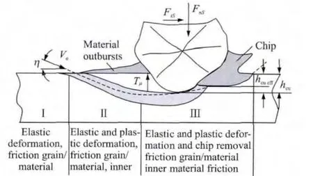
Fig.2 Deformations and chip formation[10-11]
However the material in grinding contact arc deforms severely in forms of high strain and strain rate considering that there exists strong reactions between the grains and the workpiece at the instantaneously extreme-high speed in grinding,especially in UHSG process.In this case,instead of mere consideration of material static deformation mechanism normally,strain rate effect should be taken into account since the materials turn to be adhesive,namely the constitutive relation of the materials is relevant to the strain rate effect.Furthermore there exists strain hardening,strain rate strengthening and thermal softening effects simultaneously in grinding process.Adiabatic shearing will happen with the lasting development of strain and strain rate[12].Substantially,according to the expressions of shear strain and shear strain rate in Eqs.(2-4)[13],it can be also theoretically understood that shear strain decreases while shear strain rate in-creases with the increased shear angle attributed to the increased grinding speed.Besides,both shear strain and shear strain rate increase with the decreased mean uncut chip thickness.
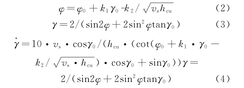
whereφis the shear angle,γthe shear strain,the shear strain rate,andγ0the rake angle of the cutting tool.φ0,k1,k2are constants decided by the workpiece material,respectively;
Additionally,Ichida,et al[14]even reported experimentally that with the increased grinding speeds,the shear angle increased and the shear strain in the shear zone decreased resulting from the fact that the chip thickness decreased and the chip length increased.Consequently,the shear zone become smaller and then the area of stress distribution become smaller too due to the increased shear strain rate.
Another dramatic phenomenon is size effect,which means specific energy(or specific tangential grinding force)increases with decreased cutting depth or mean chip cross-sectional area(Eq.(5))[15-18].

where n=1for precision grinding.The relationship is logical insofar since it takes extremely large energy to make smaller chips,but is valid only so long as chip formation is the dominant source.
Malkin[19]considered size effect related to the material micro deficiency,while Shaw[20]explained it in accordance with machining hardening.Jin and Cai[21]viewed size effect comprehensively influenced by strain hardening,strain rate strengthening,thermal softening effects as well as material deficiency,among which strain rate strengthening played a major role in some cases.Chen and Tang[13]identified that specific grinding energy was the sum of specific cutting energy and specific friction energy,and the size effect of the specific cutting energy was induced when the depth of cut or the workpiece feed speed was reduced and the average undeformed chip thickness thus decreased.Accordingly the effects of the shear strain and shear strain rate were strengthened while the temperature effect was weakened,thus increasing the shear flow stress.
Furthermore,the critical thickness of chip formation in grinding is influenced by grinding speed variation as well,owing to the combination effect of strain rate and temperature[22].
In particular,the strain rate may reach or exceed that of the materials proper propagation speed of plastic wave in UHSG.For the solid materials with the property of work hardening,at an elevated grinding speed,the gradient of the material stress-strain(σ-ε)curve increases and the proportion of plastic strain,which can turn the finished surface to the one with worse roughness,larger residual stress or greater work hardening etc,gradually decreases(Fig.3)and ultimately the material deforms elastically rather than plastically[24].Moreover,for most of ductile materials,the plastic energy,contributing more than 90%to the totally consumed energy and most of which is finally converted into heat,can also be considerably decreased.Consequently,increasing grinding speed sufficiently as high as the propagation speed of plastic wave causes the proportion of the plastic deformation within the total deformation to become smaller than that in a conventional grinding process,and thus high-quality surface with minimized work-affected layer is expected to be achieved.With respects to these,material deformation mechanism in UHSG is basically different from that in the conventional grinding process.
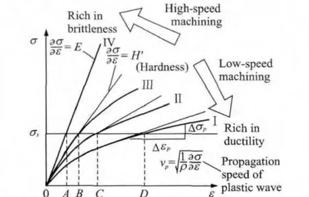
Fig.3 Stress-strain diagram in machining of ductilematerial[23]
3 Relevant Demands and New Components Development of UHSG Machine Tools
3.1 Relevant demands
The main functional modules of a UHSG machine tool are presented in Fig.4.
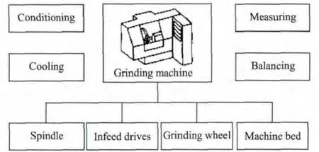
Fig.4 Functional modules of an UHSG machine tool[25]
In order to ensure the grinding machine tool with greater manufacturing capacities and higher machining accuracy under UHSG,the machine tool should have high performance spindle systems with high rotational speed and power[26-29].Meanwhile some additional demands on the machine tool design for UHSG process are primarily in the high acceleration capability and good accuracy of the machine axis.The machine bed,being of good damping and thermal characteristics,is extraordinary necessary and significant for machine tool design[30-33].Grinding wheels for UHSG,considering superabrasives and high bonding strength,as well as being balanced,are advisable and crucial.High pressure coolant systems with very special precision nozzles should also be considered and equipped,in which an air film exists around the grinding wheel acting as a barrier for the fluid to reach the contact area in UHSG.
3.2 Development of new components
3.2.1 Ultra-high-speed grinding motorized spindle
Grinding motorized spindle,which possesses a complex structure from the built-in motor,the lubrication and coolant,and high performance bearing technologies,is a key component for grinding machine tools[34-36].UHSG process requires the spindle with ultra-high rotational speed and high power together with outstanding precision.Especially static,dynamical and thermal characteristics are significantly involved.
The parameters power P,spindle rotational speed nsand wheel diameter dsare decisive for developing or choosing high frequency spindles.Small diameter of grinding wheel should be considered to decrease the power loss at a certain grinding wheel velocity according to Fig.5.On one hand,combined with spindle rotational speed and the interface dimension of shafts,wheel diameter can be firstly determined;on the other,wheel diameter ought to be 150-300mm as soon as possible,mainly concerning about the decreasing of air friction power loss.

whereρLis the air density and vLthe dynamic viscosity of air.
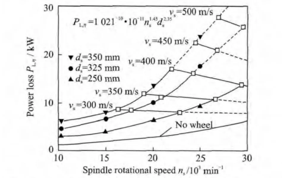
Fig.5 Small diameter of wheel considered to decrease power loss under UHSG condition[38]
Considering power loss PL,η,the following equation can be obtained.

where PKSSis the power loss of coolant friction,PSSPthe power loss of cleaning friction and Pfthe power loss of spindles inner mechanical and electrical friction.Especially,PKSSand PSSPare crucial to be considered for many real effects on spindle power.
For UHSG process,the specific tangential grinding force F′tdecreases compared with the conventional grinding because of the multiply increased grinding wheel speed.An estimated value of F′tcan be achieved according to the preceding research results about UHSG.Based on Eq.(8),the desired cutting power Pccan thus be obtained.

whereηis the motor efficiency.Grinding width b,decided by the contact width of grinding wheel and workpiece,should also be much smaller than that of conventional grinding to decrease the spindle power.Generally,1-4mm is suitable and frequently used in proceeding researches.
The total power Pfor high frequency spindle can be represented as

According to the above analysis,three critical parameters for high frequency spindle can be basically obtained.However,Inada,et al[39]developed a high frequency spindle in terms of the specific material removal rate Q′w.

whereμis the friction coefficient between grinding grits and workpiece,Fnthe normal grinding force,andαthe abrasive half-apex angle cutting into the workpiece.
Accompanying the above equations,the following equation is obtained to establish the relationship between the specific material removal rate Q′wand the spindle total power P.

According to Eq.(12),the spindle total power Pcan be determined when the aims of the specific material removal rate are preset.
Apart from the above discussed three critical parameters,others such as spindle balancing,high performance bearing,interface with grinding wheel,motor cooling,bearing lubrication,natural frequency and spindle radius expansion etc.should also be paid a lot of attention to.After the high frequency spindle developed,much experimental researches and analyses should be implemented to estimate and improve the high frequency spindle.
3.2.2 Linear direct feed drive

Fig.6 Linear direct drive technology[43]
Linear direct infeed drives(Fig.6)have come under investigation and experienced a real breakthrough for use in high-speed machine tools[40-44].Compared to conventional feed drives like using a rotary motor and a ball screw or gear-rack,the linear direct infeed drives have the potential to increase machining speed and accuracy since they can eliminate gear related mechanical problems such as backlash,large frictional and inertial loads,and structural flexibilities[45-47].
To develop or choose linear direct infeed drives,the parameter maximum stroke speed vw(here assuming linear direct infeed drives carrying workpiece directly for longitudinal moving)needs much attention.According to UHSG processes,the workpiece speed vwshould increase proportionally to the grinding wheel speed vswhen executing the high-productivity UHSG.Generally it could be 60-200m/min since the grinding wheel speed increases several times and could be up to 500m/s.In addition to this parameter,acceleration should also reach 1-5 gdecided by the maximum stroke speed and efficient stroke,considering the fact that vibrations will generate if the value is too high.Moreover,positioning accuracy,efficient stroke,continuous force,control and cooling deserve a lot of considerations,too.
3.2.3 UHSG wheels
In UHSG processes,considerably high centrifugal forces and process forces are loaded on the grinding wheel at one time[48].Meanwhile the expansion of the wheel diameter varies exponentially depending on the wheel rotational speed.Consequently the amount of expansion will be extremely higher than conventional grinding.As a result,the grinding wheel dynamic behavior plays a crucial and decisive role in UHSG.Besides,comparatively high elastic deformation of the grinding wheel takes place owning to the high wheel and workpiece speeds,which is influenced by contact stiffness and thus affects the material removal mechanism and induces machining errors.The contact stiffness mainly depends on grinding operations,grinding parameters and grinding wheel specifications such as stiffness characteristics of the wheel[49-50].
Another significant property of the grinding wheel is its damping characteristics that affect vibration between the wheel and workpiece in contact zone.Ultimately these characteristics result in a change of depth of cut,leading to the loss of form accuracy and surface quality.In addition,some other special requirements like resistance to fracture and wear,high rigidity,and good thermal conductivity are also desirable for UHSG wheels.
CBN and diamond superabrasive grinding wheels,which normally consist of a body of high mechanical strength and a comparably thin coating of superabrasive layer attached to the body using a high-strength adhesive,are always employed in the UHSG processes[51].Especially the suitability of CBN as a superabrasive material for UHSG processes is attributed to its extreme hardness,as well as its thermal and chemical durability and more wear resistance[52,53].
Additionally,the bonding is essential for the superabrasives to be embedded in the body and be retained under forces and temperatures occurring in the grinding contact zone.Simultaneously,the bonding must provide adequate space for chip removal.Usually,four different types of bondings are considered(Fig.7).As shown in Fig.7,vitrified bonding,metallic bonding and electro-plated bonding are comparably suitable for the UHSG processes just in view of circumferential speed of the grinding wheel though their corresponding material removal rate is distinguished from each other.
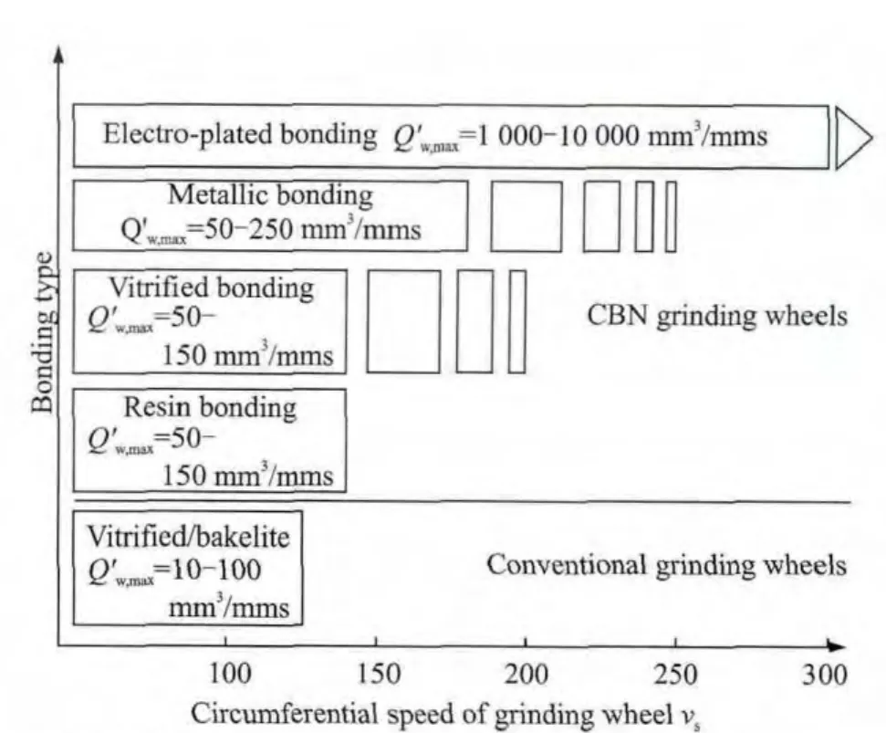
Fig.7 Bonding systems and associated material removal rates[54]
Electro-plated bonding system,where grinding wheels are coated with a single-layer superabrasive CBN grain material,is abundantly engaged in UHSG due to its high-strength adhesivity[55-56].Moreover,the maximum material removal rates are attainable at grinding wheel speed of over 200m/s since this bonding system owns a high-strength adhesive,high level of grain protrusion and a large chip space.Particularly electro-plated grinding wheels are normally believe not to employ dressing processes due to a singlelayer coating of abrasives.
Vitrified bonding system,although the potential for its practical application has yet to be fully exploited,permits grinding wheel speeds of up to 200m/s in conjunction with suitably designed bodies.Compared with other types of bondings,vitrified bonding system is considered to be easy dressing meanwhile possesses high levels of resistance to wear.The sharpening process is simplified or even eliminated in applications because the structure of vitrified bonded CBN grinding wheels leads to a subsequent chip space after dressing[57].
In recent years,researchers have given preference to brazed bonding single-layer superabrasive tools rather than galvanically bonding counterpart in many applications owning to the distinguished performance of high grit exposure,strong grit-bond adhesion and more control on uniformity of grits′spacing on the wheel surface[58-66].
Pal,et al[64]developed single-layer brazed CBN wheels where CBN grits were uniformly spaced and strongly bonded(chemical and mechanical)on the peripheral steel shank by special brazing technique(Fig.8),and together with the galvanically bonded wheel were employed to grind bearing steel for comparison of grinding performance.It′s concluded that the brazed-type wheel when grinding bearing steel were more effective and economical with less grinding forces and without wheel loading over wide ranges of the grinding parameters.It could achieve more material removal rates.Ding,et al[61]exploited a brazed CBN abrasive wheel where the CBN grains were distributed linearly in the working zones of the abrasive wheels to investigate grindability and surface integrity of cast nickel-based superalloy(Fig.9).
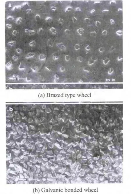
Fig.8 Surface topography of SEM micrographs[64]

Fig.9 Morphology of brazed CBN abrasive wheel[61]
Tian,et al[62]developed a brazed singlegrain diamond grinding wheel for ultra-high-speed grinding superalloy material in order to investigate speed effect on critical thickness of chip formation and grinding force.Chen,et al[63]used brazed diamond wheels of two different grit sizes to explore the grinding characteristics and removal mechanisms in ultra-high-speed grinding of three engineering ceramics.They concluded that the brazed diamond wheels could be used for ultra-high-speed grinding of ceramics with acceptable surface roughness and energy consumption.
In addition to the need to select the appropriate bonding for the grinding wheel,the body should also meet some specific demands on geometry and material.Due optimization aiming to avoid excessive stresses in the body and achieve the smallest possible total extension is indispensably required considering the ultra high circumferential speeds of the grinding wheel.In particular,the maximum stress in the wheel body must not exceed the strength limits of the wheel body material in the optimizing process.In addition,the mass of the body should also be reduced to move critical natural frequencies of the system in the direction of higher rotational speeds as far as possible.
In contrast to the conventional rectangularsection body shape,the omission of the central hole and the shape optimization by means of a defined change in thickness over the radius are decisively important and necessary for UHSG wheels,which drastically reduces the maximum stress and strain and leads to a approximately constant stress and strain level in the body(Fig.10).
Furthermore,the body material determines the static and dynamic behaviors of the grinding wheel as well.Currently,metallic materials,mainly including steel and aluminum alloys,are practically used for superabrasive wheels due to their high strength.However,another material suiting for UHSG wheel bodies is carbon fiber reinforced plastics(CFRP)(Fig.11),which is distinguished by its extremely high strength and ri-gidity.

Fig.10 Optimization of the UHSG wheel body[67]

Fig.11 CFRP UHSG wheel(acc.to KREBS and RIEDEL)
Due to its low density,up to 90%less weight,CFRP material can provide some additional damping,although the reduced weight of wheel body increases the natural frequency of the wheel significantly.Particularly,although the modulus of elasticity of CFRP is lower than that of steel,its extremely low value in the specific weight results in a higher value of E/γ-ratio which can significantly suppresses radial expansion of the wheel body,and it means a preference for the grinding wheel application(Table 1).Additionally,extremely low coefficient value of linear expansion of CFRP indicates another advantage in applying this particular material to the UHSG wheel body.
Yamazaki,et al[37]distinctly concluded that the maximum value of maximum principal stress of core is decisively influenced by core material.Moreover,the value using CFRP as core material is only about 1/5than that using hardened steel as core material and 1/3than that using titanium as core material.In Fig.12,the critical speed in case(5)(612m/s)is larger than that in case(4)(518m/s).
To further investigate the effects of wheel body material on grinding process,especially the CFRP behavior,Tawakoli,et al[51]experimentally concluded that higher value of E/γ-ratio of CFRP resulted in a lower radial expansion.Addi-tionally the higher damping property of CFRP leaded to a reduction in grinding forces.

Table 1 Material properties of steel and CFRP[51]
Van Brussel and Van[41]gave the theoretically calculation of the amount of wheel expansion.

where uis the displacement of wheel,γthe density,ωthe angular velocity,r the wheel radius,ν the Poisson′s ratio,Ethe Young′s modulus,and gthe gravitation acceleration.
Obviously,the value of wheel displacement decreases as the value of E/γ-ratio increases when keeping other parameters constant.From this equation,it can be achieved that the value of wheel displacement increases squarely with angular velocity.Accordingly,amount of wheel expansion can be extraordinarily large under the conditions of UHSG and results in a reduction in the size of workpiece if the wheel infeed is with-out any compensation.Yui,et al[68]investigated effects of compensation on grinding dimensions and tried a compensation method of workpiece thickness based on calculated results by controlling the wheel infeed.
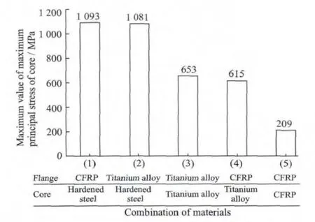
Fig.12 Stress vs.combination of flange material and core material[37]
For the whole grinding wheel,dynamic balancing is obligatory before UHSG processes are carried out since even little unbalanced mass can induce great centrifugal forces and cause spindle vibration,which influences grinding process results.Moreover some related performance including stress and strain of grinding wheel can be analyzed with the help of finit element method(FEM)to optimize the wheel shape.Furthermore some high precise sensors such as acoustic emission can be employed to monitor the condition of the grinding wheel when implementing UHSG processes practically.Subsequently the grinding wheel should also go through some rotational tests to demonstrate and ensure its safety before used in UHSG process experiments.
3.2.4 Cooling
Although there exists high demand for reduction in cooling lubricants in terms of ecological and economic aspects,distinguished from cutting like turning,milling,and drilling in which remarkable progress has been made in reducing cutting fluids,UHSG brings in a quantity of heat produced by air friction,cooling and cleaning fluid and grinding energy which may lead to much thermal damage to the workpiece surface layer as well as loading and wear of the grinding wheel,resulting in micro-cracks and tensile residual stresses at the ground surfaces that deteriorate the surface quality and integrity of the ground surface[69-71].In this respect,a mass and efficient coolant supply system plays a prerequisite and decisive role in UHSG processes.
To deliver the cutting fluids in grinding processes,previous studies have indicated that in addition to coolant type,composition and filtration,especially coolant supply(nozzle position,nozzle geometry,supplied flow rate and jet characteristics)can affect process and process results[72-75].Therefore analyzing and optimizing cooling and lubrication during grinding,particularly in UHSG processes,are extraordinarily essential and important[76-78].
However,there is no much necessarity to deliver large volume fluids since the function of lubrication decisively depends on fluids entering the contact region,that is to say,no fluid entering the grinding zone leads to ineffective fluid delivery.To feature this,a critical term″effective fluid rate″is generally used in many studies,which indicates the quantity of cutting fluid passing through the grinding zone.
A theoretical model of fluid flow through a porous grinding wheel based on experimental results was developed by Guo,et al[79]to calculate the effective flow rate by means of average tangential velocity,fluid depth of penetration and some other parameters.Engineer,et al[80]directly measured the effective flow rate using conventional fluid application by separating and collecting all the fluid passing through the grinding zone and the experimental values ranged from 5%to 30%of supplied flow rate for different width of wheels,nozzle positions and grinding conditions.Akiyama,et al[81]indicated that the maximum film thickness was estimated to be 40μm when the cutting fluid was directed at some angle to the wheel periphery thanks to the fluid carried into the grinding zone by adhesion on the wheel periphery of air boundary layer,while 80μm in case of delivering the same volume of fluid at the same velocity but with a nozzle positioned so that the fluid was directed straight towards the grinding zone.
Air boundary layer is also investigated by many research fellows since it reverses back cutting fluids and thus influences grinding process a lot.Inasaki[82]considered it as a product of two major air flows around the wheel surface:(i)air flow in the circumferential direction;(ii)air spouting in the normal direction to the wheel surface induced by centrifugal force of wheel rotation(Fig.13),and ultimately hindered effective coolant entry.Ebbrell,et al[83]investigated the effects of the air boundary layer through measuring the efficient volumetric flow rate(Fig.14)and the pressure and velocity of the boundary layer and deemed that there existed a minimum gap for the fluid passing through.Cutting fluid delivery was also optimized to maximize flow rate beneath the wheel.In comparison with tangential nozzle and angular nozzle position,intermediate nozzle position was proposed in terms of surface texture and scatter about the target size,which was contrary to the common opinion that nozzle position should be tangential to the wheel periphery as possible.
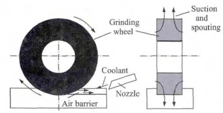
Fig.13 Coolant supply and air barrier in grinding[82]
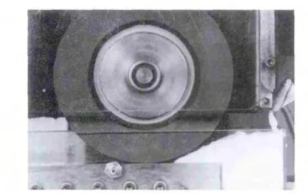
Fig.14 Cutting fluid backing up due to boundary layer effects[83]
In order to make the coolant penetrate the air barrier and consequently get to the contact zone,Hryniewicz,et al[84]investigated the issue of fluid rejection on the wheel and concluded that there existed a critical wheel speed Vcrit,below which no fluid was rejected from the wheel and the value was inversely proportional to the channel height in the grinding zone.
Grinding with control of coolant velocity(3-17m/s)(Fig.15),Ramesh,et al[85]experimentally suggested the existence of threshold flow rate below which the ground surface damage was apparent.Coolant velocity control further brought down this threshold through effective penetration,introducing lubrication effect at the grinding wheel-work interface and finally improving the surface finish.
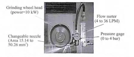
Fig.15 Metered quantity nozzle design integrated to the grinding wheel head[86]
Banerjee,et al[86]developed a twin jet nozzle along with a simple working system for its implementation to help break the air layer before it reached the grinding zone,keep air suction from the sides,and force the adequate fluid into the grinding zone(Fig.16).By separating,collecting and measuring fluid flow actually passing through the grinding zone for different nozzle locations and orientations,it was concluded that there existed certain locations around wheel periphery where placement of the developed nozzle yielded better efficient flow rate.
Use of high pressure cooling with optimal nozzle geometry can help decrease the workpiece surface roughness.Kovacevic,et al[87]used a free jet nozzle with a diameter of 0.46mm,from which a water jet was sent out at a maximum pressure of 380MPa with a velocity of 365m/s and therefore a flow rate of only 3.6l/min.Process forces decreased by 25%and surface roughness decreased by 50%compared to conventional flooding coolant supply.
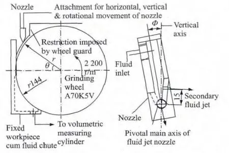
Fig.16 Experimental set-up and the developed nozzle[86]
However,comparatively few of the previous researches are implemented under the condition of UHSG,even high speed grinding(HSG).More effects on grinding results will be brought in due to more complicate and significant phenomenon of the formation of air boundary layer in UHSG.The increased velocity and strengthened momentum of the reversed air flow deteriorate the cooling condition and reduce the efficient flow rate to a large extent with increasing grinding wheel velocity multiply.According to the previous results,high velocity jet of cutting fluid is proposed to penetrate the air boundary layer with less quantity of cutting fluid,high pressure and consideration of the nozzle geometrical shape and position.
Practically there is no entirely uniform statements can be made as to high pressure cooling,and detailed quantitative relationships between grinding process parameters and necessary conditions in high pressure wheel cleaning are not established yet.Some related investigations on air boundary layer and efficient flow rate in grinding process should also need to be further carried out,especially in UHSG.In future researches,cooling methods including inner jet cooling which means the combination of jet and grinding wheel inner cooling for heat transfer enhancement,high pressure nozzle towards the grinding zone together with scraper plates and their combinations ought to be considered.
4 Research Activities on UHSG Process
Ferlemann,et al[67]comparatively early investigated the UHSG processes based on the developed 500m/s UHSG machine tool.He verified that the specific grinding forces decreased with the increased wheel speed.Particularly the reduced amplitude was conspicuous from 180m/s to 210m/s,and machining efficiency of wheel speed 340m/s was up to three times as that of wheel speed 180m/s when keeping the same specific grinding forces.Additionally,Inada[55]claimed that specific grinding energy was improved with the increased wheel speed due to the reduced maximum chip thickness,which was explained by that as much heat generated in UHSG material FC200,the material emerged thermal expansions and thus resulted in an increase in grinding resistance,ultimately leading to the increased specific grinding energy.
By means of UHSG,specific material removal rates of 140mm3/mms were attainable in grinding operation at the grinding wheel speed 300m/s,employing electroplated CBN grinding wheels when narrow slots were applied to pump rotors made of 100Cr6hardened roller bearing steel[6].Ramesh et al[17]indicated that the surface finish was improved and the surface texture of the ground ceramics was free from surface damage.In addition,the grinding ration of the diamond wheel was found to be almost doubled in the case of grinding Al2O3and ZrO2at 160m/s compared to the case at 40m/s.
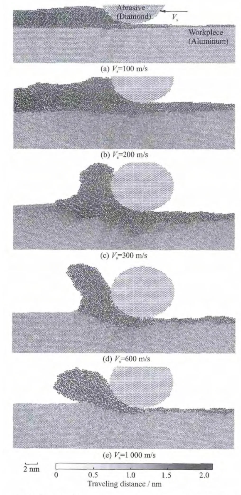
Fig.17 Snapshots of atomic arrays in grinding process simulation under various grinding speeds[23]
Shimizu,et al[23]employed the molecular dynamics simulation on the UHSG below and beyond static propagation speed of aluminum(vsp=200-500m/s)(Fig.17)and claimed that with the increased grinding speed,plastic deformation in front of the abrasive became smaller and smaller and was hardly observed in Fig.17(d).Meanwhile the number of the slip plane decreased further and further.Particularly when the grinding speed was sufficiently higher than the static propagation speed of material plastic(Fig.17(e)),atoms in the cutting chip had lost the crystallinity and were in condition of melt rather than plastic deformation.The number of the generated slip planes to the depth direction of the workpiece were few.They also concluded experimentally that the tangential grinding force dropped down once the grinding speed went beyond static propagation speed of aluminum though the normal force rose to a certain extent,and indicated the decreasing of the grinding energy.
Ichida,et al[14]indicated that the workpiece(bearing steel)surface roughness at wheel speeds higher than 200m/s decreased by 20%-30%compared with that of the conventional wheel speed of 60m/s,which was considered to be closely related to the reduction of the side swelling formed along both sides of the groove with the increased grinding speed according to Fig.18.Moreover,it was also observed that although the tangential force decreased,the normal force increased slightly with the increased speed,and consequently the ration of normal force and tangential force decreased.
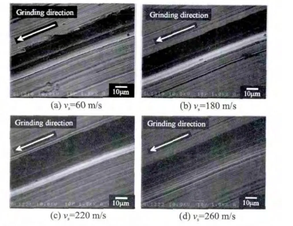
Fig.18 Typical SEM images of grinding grooves formed at wheel speeds of 60m/s,180m/s,220m/s and 260m/s[14]
Linke,et al[88]made a combination of speed stroke grinding and HSG with regard to sustainability to boost both process performance and workpiece quality.The experimental results confirmed that the combination of speed stroke grinding and high speed machining can decrease grinding energy,grinding power,and tool wear.Although higher table speeds leaded to an increase in workpiece surface roughness,it was acceptable in the scope of roughing operations.Moreover,the worsening of surface roughness could be slowed down through simultaneously applying higher grinding wheel speeds.Tian,et al[62]showed that the grinding speed affected the division of grinding process and the critical thickness of chip formation,meanwhile machinability was changed due to the speed effect and these changes were caused by the alternative variation of the leading position between the strain rate strengthening effects and the thermal softening effects.
Although there does have many investigations on UHSG processes,the grinding mechanism at grinding speed higher than 200m/s is not sufficiently elucidated yet.The previous UHSG results have shown that there really exists extreme distinction in varying tendency of normal grinding force,specific energy,surface roughness and other parameters for different materials and grinding conditions.Chip formation mechanism for different materials especially related to difficult-to-machine materials such as titanium and superalloy still needs more and further investigations to demonstrate the dominance of UHSG technology.
5 Conclusions
Applying grinding technology can achieve considerably good finish surface and outstanding workpiece quality which could not be attained by other machining methods.UHSG technology,by means of elevated grinding wheel speeds and increased workpiece speeds,can further improve the machined workpiece quality together with satisfying productivity just as the preceding process analysis and previous experimental results indicating.However in view of practical application,grinding wheel speeds are personally thought to be not reasonable and beneficial just as elevating wheel speeds more and more.Besides economical aspect,some crucial technologies including extremely high power spindles,suitable grinding wheels,quantity of grinding heat,harder efficient cooling,related measuring approach etc.An abundance of further work and researches are needed to be taken up for the truth.State of the art of the maximum practical grinding wheel speeds are mainly 200-300m/s for UHSG and some available and significant results have been achieved to demonstrate advantages of UHSG.
Despite this,the grinding mechanism at grinding speed higher than 200m/s is not yet suf-ficiently elucidated.The previous UHSG results have shown that there exists extreme distinction in varying tendency of normal grinding force,specific energy,surface roughness and other parameters for different materials and grinding conditions.Chip formation mechanism for different materials especially related to difficult-to-machine materials such as titanium and superalloy under UHSG still needs more and further investigations.
Some related equipments are therefore necessary to realize UHSG technology.High speed and superior performance machine tools are preliminary and crucial,which mainly consist of high speed and power spindle systems,fast workpiece infeed systems,good stiffness and damping machine beds and especially good performance grinding wheels.Additionally,the corresponding coolant delivery methods and systems are also absolutely essential.Not least of all,improved UHSG process needs much attention and investigation as well.
Superabrasive especially CBN grinding wheels with improved bonding systems are mostly employed in UHSG technology for their high hardness,wear resistant and good bonding strength.In addition to vitrified and electro-plated bonding systems,brazed bonding single layer superabrasive tools are drawn more and more attention in grinding,especially UHSG applications,due to its high grit exposure,strong gritbond adhesion and more control on uniformity of grits′spacing on the wheel surface.In addition,CFRP material is supposed to be employed for the grinding wheel body considering its superiority of extremely low specific strength and good damping characteristics.Furthermore,due to its low density,the gravity load and centrifugal stress from grinding wheels are greatly decreased,which can improve the natural frequency of the spindle systems.
Moreover,improved effective flow rate is decisively important for UHSG application since a quantity of the produced heat induces to thermal damage.Currently there are no absolutely effi-cient coolant delivering methods although many theoretical and experimental investigations have been carried out in UHSG.In future researches,cooling methods,including inner jet cooling which means the combination of jet and grinding wheel inner cooling for the effect of heat transfer enhancement,high pressure nozzle towards the grinding zone together with scraper plates and their combinations,ought to be considered.
Extremely precisise and resultful in-process measuring systems are also prerequisite to collect related performance parameters in grinding due to the feature that UHSG is a high-frequency and high-precision machining method.
In addition,grinding process especially process parameters are considerably significant in UHSG.In particular,proper speed ratio and cutting depth related to grinding force,specific energy,surface integrity and even chip formation mechanism have a decisive influence on grinding results.
Apart from experimental methods,modeling and simulation of UHSG processes can be also conducted to assess and optimize the process of cutting and chip formation intuitively.FEMs and molecular dynamic models are commendable approaches to simulate process status parameters such as grinding heat,deformation,grinding forces etc.Afterwards some experiments can be implemented to verify the output simulation results and further for modification.
[1] Comley P,Walton I,Jin T,et al.A high material removal rate grinding process for the production of automotive crankshafts[J].CIRP Ann,2006,55:1-4.
[2] Jackson M J,Paulo Davim J.Machining with abrasive[M].New York:Springer Science Business Media,2011.
[3] Kim J.A comparison of conventional and high speed grinding of AISI 52100steel[D].Connecticut:University of Connecticut,1997.
[4] Sheng X M.Ultra-high-speed grinding technology[M].Beijing:Mechanical Industry,2010.(in Chi-nese)
[5] Fu Y C,Zhang Z W,Xu J H,et al.High efficiency deep grinding of directional solidified nickel-based superalloy turbine blade root[J].J Nanjing Univ Aeronaut Astronaut,2014,46(2):190-196.(in Chinese).
[6] Klocke F,Brinksmeir E,Evants C,et al.Highspeed grinding-fundamentals and state of the art in Europe,Japan and the USA[J].CIRP Ann,1997,46(2):715-724.
[7] Jackson M J,Davis C J,Hitchiner M P,et al.Highspeed grinding with CBN grinding wheels-applications and future technology[J].J Mater Process Technol,2001,110:78-88.
[8] Oliveira J F G,Silva E J,Guo C,et al.Industrial challenges in grinding[J].Ann CIRP Manuf Technol,2009,58:663-680.
[9] Koenig W,Klocke F.Fertigungsverfahren(Band 2):Schleifen,Honen,Laeppen[M].Duesseldorf:VDI Verlag,1996.
[10]Marinescu I D,Hitchiner M,Uhlmann E,et al.Handbook of machining with grinding wheel[M].London:CRC Press Taylor &Francis Group,2007.
[11]Peklenik J.Complexity in manufacturing systems[J].J Manuf Syst,1995,24(1):17-25.
[12]Wang L L,Yu T X,Li Y C.Advances in impact dynamics[M].Hefei:Press of University of Science and Technology of China,1992.(in Chinese)
[13]Chen Y P,Tang J Y.Research on the size effect involved in grinding[J].Chin Mech Eng,2007,18(17):2033-2036.(in Chinese)
[14]Ichida Y,Sato R,Morimoto Y,et al.Formation mechanism of finished surface in ultrahigh-speed grinding with cubic boron nitride(cBN)wheels[J].JSME Int,2006,49(1):100-105.
[15]Singh V,Venkateswara Rao P,Ghosh S.Development of specific grinding energy model[J].Int J Mach Tool Manu,2012,60:1-13.
[16]Hwang T W,Evans C J,Malkins S.Size effect for specific energy in grinding of silicon nitride[J].Wear,1999,225/229:862-867.
[17]Ramesh K,Yeo S H,Gowri S,et al.Experimental evaluation of super high-speed grinding of advanced ceramics[J].Int J Adv Manuf Tech,2001,92:87-92.
[18]Stephenson D J,Jin T.Physical basics in grinding[C]∥The Proceedings of the First European Conference on Grinding.Aachen,German:[s.n.],2003:13-1-13-21.
[19]Malkin S.Grinding technology—Theory and applications of machining with abrasives[M].New York:Ellis Horwood,1989.
[20]Backer W R,Marshall E R,Shaw M C.The size effect in metal cutting[J].Trans ASME,1952,74:61-64.
[21]Jin T,Cai G Q.Strain rate strengthening of workpiece material and the size effect involved in grinding[J].Chin Mech Eng,1999,10(12):1401-1417.(in Chinese)
[22]Li Y F.Theory of metal cutting processing[M].Beijing:Mechanical Industry Press,1985.
[23]Shimizu J,Zhou L B,Eda H.Simulation an experimental analysis of super high-speed grinding of ductile material[J].J Mater Process Technol,2002,129:19-24.
[24]Karman T,Duwez P.The progress of plastic deformation in solids[J].J Appl Phys,1950,21:987-992.
[25]Toenshoff H K,Karpuschewski B,Mandrysch T.Grinding process achievements and their consequences on machine tools challenges and opportunities[J].CIRP Ann,1998,47(2):651-668.
[26]Kreith F,Mahajan R.Vibration damping,control,and design[M].London:CRC Press Taylor &Francis Group,2007.
[27]Garitaonandia I,Albizuri J,Hernandez-Vazquez J M,et al.Redesign of an active system of vibration control in a centerless grinding machine:Numerical simulation and practical implementation[J].Pre Eng,2013,1-32.
[28]Leonesio M,Parenti P,Cassinari A,et al.A timedomain surface grinding model for dynamic simulation[J].CIRP Ann,2012,4:166-171.
[29]Fernandes M H,Garitaonandia I,Albizuri J,et al.Simulation of an active vibration control system in a centerless grinding machine using a reduced updated FE model[J].Int J Mach Tool Manu,2009,49:239-245.
[30]Corbett J,Morantz P,Stephenson D J,et al.An advanced ultraprecision face grinding machine[J].Int J Adv Manuf Tech,2002,20:639-648.
[31]Krajnik P,Kopac J,Sluga A.Design of grinding factors based on response surface methodology[J].J Mater Process Technol,2005,162-163:629-636.
[32]Heisel U,Gringel M.Machine tool design requirements for high-speed machining[J].CIRP Ann,1996,45(1):389-392.
[33]Lopez L N,Lamikiz A.Machine tools for high performance machining[M].Elgoivar:Springer,2009.
[34]Weck M,Koch A.Spindle bearing systems for high speed applications in machine tools[J].CIRP Ann,1993,42(1):445-448.
[35]Nakamura S.High speed spindles for machine tools[J].Int J Jpn Soc Precis Eng,1996,30(4):291-294.
[36]Yeo S H,Ramesh K,Zhong Z W.Ultra-high-speed grinding spindle characteristics upon using oil/air mist lubrication[J].Int J Mach Tool Manu,2002,42:815-823.
[37]Yamazaki S,Syoji K,Kuriyagawa T,et al.Development of an ultra-high speed cutting wheel[J].Key Eng Mater,2003,238-239:271-276.
[38]Ferlemann F.Schleifen mit hochsten Schnittgeschwindigkeiten[D].Aachen:Technische Hochschulle Aachen,1992.
[39]Inada Y,Syoji K,Kuriyagawa T,et al.Development of wheel spindle for ultra-high speed surface grinding machine—Studies on ultra-high speed grinding(1st Report)[J].J Jpn Soc Precis Eng,1996,62(4):569-573.
[40]Alter D M,Tsao T C.Control of linear motors for machine tool feed drives:Design and implementation of H∞optimal feedback control[J].J Dyn Syst-T ASME,1996,118:649-656.
[41]Van Brussel H,Van P.Robust control of feed drives with linear motors[J].CIRP Ann,1998,47(1):325-328.
[42]Inasaki I.Surface grinding machine with a linearmotor-driven table system:Development and performance test[J].CIRP Ann,1999,48(1):243-246.
[43]Weck M,Krueger P,Brecher C.Limits for controller settings with electric linear direct drives[J].Int J Mach Tools Manuf,2001,41:65-88.
[44]Brahms U.Regelung von lineardirektantrieben fuer werkzeugrnaschinen[D].Lower Saxony:Universitat Hannover,1998.
[45]Favre E,Cardoletti L,Jufer M.Permanent-magnet synchronous motors:A comprehensive approach to cogging torque suppression[J].IEEE T Ind Electron,1993,29(6):1141-1149.
[46]Zhu Z Q,Howe D.Analytical prediction of the cogging torque in radialfield permanent magnet brushless motors[J].IEEE T Magn,1992,28:1371-1374.
[47]Zeppenfeld C.Schnellhubschleifen vonγ-Titanaluminiden[D].Aachen:Technische Hochschulle Aachen,2005.
[48]Tawakoli T.High efficiency deep grinding:Technol-ogy,process,planning and application[M].London:Mechanical Engineering Publication,1993.
[49]Yamada T,Lee H S,Miura K.Contact stiffness of grinding wheels due to the difference of table feed rate[J].Adv Mater Res,2009,76-78:137-142.
[50]Warnecke G,Barth C.Optimization of the dynamic behavior of grinding wheels for grinding of hard and brittle materials using the finite element method[J].CIRP Ann,1999,48(1):261-264.
[51]Tawakoli T,Reinechke H,Vesali A.An experimental study on the dynamic behavior of grinding wheels in high efficiency deep grinding[J].CIRP Ann,2012,1:382-387.
[52]Von Arciszewski A.Tiefschleifen mit kon tinuierlichem abrichten(CD)—Verfahrens grundlagen und anwendungen[D].Aachen:Technische Hochschulle Aachen,1991.
[53]Werner G.High-effciency deep grinding(HEDG)—Eine neue variante des Hochlei stungsschleifens verbindet das hochgesch windigkeits und tiefschleifen[D].North Rhine-Westphalia:Industrieforum fur technologie,1995.
[54]Kopac J,Krajnik P.High-performance grinding—A review[J].J Mater Process Tech,2006,175:278-284.
[55]Inada Y.Studies in ultra high speed grinding[D].Tohoku:Tohoku University,1996.
[56]Jackson M J,Barlow N,Hon K K B.Computer aided design of high performance grinding tools[J].P I Mech Eng B—J Eng,2001,215:583-588.
[57]Klocke F,Koenig F.Appropriate conditioning strategies increase the performance capabilities of vitrifiedbond CBN grinding wheels[J].CIRP Ann,1995,44(1):305-310.
[58]Inasaki I,Toenshoff H K,Howes T D.Abrasive machining in the future[J].CIRP Ann,1993,43(2):723-732.
[59]Chattopadhyay A K,Chollet L,Hintermann H E.On performance of brazed bonded monolayer diamond grinding wheel[J].CIRP Ann,1991,40(1):347-350.
[60]Li Q L,Xu J H,Su H H.Simulation of temperature field in ultra-high frequency induction heating and verification[J].Trans Nanjing Univ Aeronaut Astronaut,2013,30(2):155-161.
[61]Ding W F,Xu J H,Chen Z Z,et al.Grindability and surface integrity of cast nickel-based superalloy in creep feed grinding with brazed CBN abrasive wheels[J].Chin J of Aeronaut,2010,23(4):501-510.
[62]Tian L,Fu Y C,Yang L,et al.Investigations of the speed effect on critical thickness of chip formation and grinding force in high speed and ultra-high speed grinding of superalloy[J].Chin J Mech Eng,2013,49(9):169-177.(in Chinese)
[63]Chen J Y,Shen J Y,Huang H,et al.Grinding characteristics in high speed grinding of engineering ceramics with brazed diamond wheels[J].J Mater Process Technol,2010,210(6/7):899-906.
[64]Pal B,Chattopadhyay A K,Chattopadhyay A B.Development and performance evaluation of monolayer brazed cBN grinding wheel on bearing steel[J].Int Adv Manuf Technol,2010,48(9/12):935-944.
[65]Chen J Y,Huang H,Xu X P.An experimental study on the grinding of alumina with a monolayer brazed diamond wheel[J].Int J Adv Manuf Tech,2009,41(1/2):16-23.
[66]Chen Y,Ding L Y,Fu Y C,et al.Dry grinding of titanium alloy using brazed monolayer cBN wheels coated with graphite lubricate[J].Trans Nanjing Univ Aeronaut Astronaut,2014,31(1):104-110.
[67]Ferlemann F,Koenig W.CBN grinding at five hundred m/s[J].Ind Diamond Rev,1991,51(2):72-79.
[68]Yui A,Lee H S.Surface grinding with ultra high speed CBN wheel[J].J Mater Process Technol,1996,62:393-396.
[69]Zhong Z W,Venkatesh V C.Recent developments in grinding of advanced materials[J].Int J Adv Manuf Technol,2009,41:468-480.
[70]Zhang J Z,Tan X M,Liu B,et al.Heat transfer on grinding workpiece surface subjected to mist/air impinging jet[J].J Nanjing Univ Aeronaut Astronaut,2012,44(5):741-746.(in Chinese)
[71]Kuriyagawa T,Syoji K,Ohshita H.Grinding temperature within contact arc between wheel and workpiece in high-efficiency grinding of ultrahard cutting tool materials[J].J Mater Process Technol,2003,136:39-47.
[72]Sinot O,Chevrier P,Padilla P.Experimental simulation of the efficiency of high speed grinding wheel cleaning[J].Int J Mach Tool Manu,2006,46:170-175.
[73]Alberdi R,Sanchez J A,Pombo I,et al.Strategies for optimal use of fluids in grinding[J].Int J Mach Tool Manu,2011,51:491-499.
[74]Morgan M N,Jackson A R,Wu H,et al.Optimization of fluid application in grinding[J].CIRP Ann,2008,57:363-366.
[75]Aurich J C,Kirsch B.Improved coolant supply through slotted grinding wheel[J].CIRP Ann,2013,62:363-366.
[76]Campbell J P.Optimized coolant application[C]∥First International Machining and Grinding Conference,Society of Manufacturing Engineering.Michigan,USA:[s.n.],1995:11-17.
[77]Okuyama S,Nakmura Y,Kawamura S.Cooling action of grinding fluid in shallow grinding[J].Int J Mach Tools Manuf,1993,33(1):13-23.
[78]Su H H,Ma K,Fu Y C,et al.Investigation of enhancing heat transfer in grinding zone with loop heat pipe wheel[J].J Nanjing Univ Aeronaut Astronaut,2012,44(5):741-746.(in Chinese)
[79]Guo C,Malkin S.Analysis of fluid flow through the grinding zone[J].J Manuf Sci E-T ASME,1992,114(4):427-434.
[80]Engineer F,Guo C,Malkin S.Experimental measurement of fluid flow through the grinding zone[J].J Eng Ind,1992,114(1):61-66.
[81]Akiyama T,Shibata J,Yonetsu S.Behaviour of grinding fluid in the gap of the contact area between a grinding wheel and workpiece[C]∥Proceedings of the 5th International Conference on Production Engineering.Tokyo:[s.n.],1984:52-60.
[82]Inasaki I.Fluid film in the grinding arc of contact[J].CIRP Ann,1998,48(1):261-264.
[83]Ebbrell S,Wooley N A,Tridimas Y D,et al.The effects of cutting fluid application methods on the grinding process[J].Int J Mach Tools Manuf,2000,40:209-223.
[84]Hryniewicz P,Szeri A A,Jahanmir S.Coolant flow in surface grinding with non-porous wheels[J].Int J Mech Sci,2000,42(12):2347-2367.
[85]Ramesh K,Huang H,Yin L.Analytical and experimental investigation of coolant velocity in high speed grinding[J].Int J Mach Tools Manuf,2004,44:1069-1076.
[86]Banerjee S,Ghosal S,Dutta T.Development of a simple technique for improving the efficacy of fluid flow through the grinding zone[J].J Mater Process Technol,2008,197:306-313.
[87]Kovacevic R,Mohan R.Effect of high speed grinding fluid on surface grinding performance[C]∥the 1st International Machining and Grinding Conference.Michigan:[s.n.],1995:917-931.
[88]Linke B,Duscha M,Klocke F,et al.Combination of speed stroke grinding and high speed grinding with regard to sustainability[EB/OL].http:∥escholarship.org/uc/item/5qs5k8pv,2011.
猜你喜欢
杂志排行
Transactions of Nanjing University of Aeronautics and Astronautics的其它文章
- Threshold Selection Method Based on Reciprocal Gray Entropy and Artificial Bee Colony Optimization
- Optimal Power Management for Antagonizing Between Radar and Jamming Based on Continuous Game Theory
- Parameter Optimization Method for Gaussian Mixture Model with Data Evolution
- Runge-Kutta Multi-resolution Time-Domain Method for Modeling 3DDielectric Curved Objects
- Semantic Social Service Organization Mechanism in Cyber Physical System
- Fast Numerical Solution to Forward Kinematics of General Stewart Mechanism Using Quaternion
