Structural Performance of Precast and Cast-in-situ Ultra High Strength Concrete Sandwich Panel
2014-04-16RamachandraMurthyRameshKumarSmithaGopinathPrabhatRanjanPremNageshIyerandReshmiBalakrishnan
A.Ramachandra Murthy,V.Ramesh Kumar,Smitha Gopinath,Prabhat Ranjan Prem,Nagesh R.Iyerand Reshmi Balakrishnan
1 Introduction
In the building construction industry,cladding walls generally provide an envelope to the building for protection against the elements,thermal insulation, fire protection and may also provide a certain architectural design to enhance the aesthetics of the building.Cladding panels are typically non-load-bearing in the plane of the panel and are generally designed for out-of-plane loading due to wind loads.Conventional cladding panels are usually made from precast reinforced concrete thick skins with a foam core material used to provide the required insulation.Although these types of cladding panels have been widely used for years,they have several drawbacks.Being exposed to the elements,they are susceptible to corrosion of the steel reinforcement,especially in humid environments.Also,they add much dead weight to the building,which in turns adds significantly to the size of members,including beams,columns and foundation.Other disadvantages of the heavy-weight reinforced concrete panels are the difficulties associated with shipping and handling,which impact the speed of installation[Abdel and Sharaf(2010)].
Sandwich panels are being used in many applications ranging from aerospace to automotive and transportation,but are not as common in structural applications.Sandwich panels are engineered materials in which a material of very low density is introduced between two composites phase sheets.Introduction of new material increases the thickness of the panel which in turn increase the moment of inertia,stiffness and hence the ultimate strength.The basic concept behind the sandwich panels are similar to that of an I Section,where the phase sheets acts as the flange and core as web.Construction systems based on sandwich panels are commonly used worldwide for intensive building production.Sandwich panels are typically constituted by two concrete layers which are separated by an internal insulation layer of various materials(i.e.expanded and extruded polystyrene,rigid polyurethane foam)and are usually joined with “shear connectors”(i.e.truss connectors)able to transfer the longitudinal interface shear between the layers so as to ensure a fully-composite or a semi-composite behaviour of the sandwich panel.
Basunbul et al.(1991)investigated the flexural behavior of ferrocement sandwich panels considering the number of wire mesh layers,the skeletal steel,the web mesh reinforcement and the number of webs.Ultimate moment capacities were computed analytically using conventional reinforced concrete theory.The analytical results were compared with the experimental results by tests on 12 sandwich panels.Benayoune et al.(2008)studied the structural behaviour of precast concrete sandwich panels(PCSP)under flexure both experimentally and theoretically.Their experimental results showed that the mode of failure and crack pattern of PCSP acting as slab elements were very similar to those of solid slabs especially when the two concrete wythes act in a fully composite manner.The finite element analysis of the PCSP resulted in reasonable estimation of the experimental load–deflection curves as well strain in shear connectors.Mainul Islam and Aravinthan(2010)developed an innovative fibre composite sandwich panel made of glass fibre reinforced polymer skins and a modified phenolic core material for building and other structural applications.The two-and four-edge supported sandwich panels with different fibre orientations and fixity systems between panel and joist were tested under point load and uniformly distributed load(UDL)to determine their strength and failure mechanisms.Sohel et al.(2012)investigated the performance of Steel-Concrete-Steel(SCS)sandwich structure with novel shear connectors such as J-hook and cable shear connectors.An analytical method to predict the ultimate strength of the Steel–Concrete–Steel sandwich beams with various types of shear connectors was developed and its accuracy was ascertained by comparing with the test results.Johnson and Li(2012)studied the four-point bending response and failure mechanisms of sandwich panels with corrugated steel faces and either plain or fibre-reinforced foamed concrete core.It is found that the fibre-reinforcement largely enhances the mechanical behaviour of foamed concrete and composite sandwich panels.Rodrigo Lameiras et al.(2013)evaluated the mechanical behaviour of sandwich panels developed by combining fibre reinforced concrete layers and fibre reinforced polymer connectors.Ali Shams et al.(2014)proposed an analytical model for sandwich panels made of textile-reinforced concrete.The results of the experimental investigations and an analytical model that enables a realistic calculation of the load-bearing-de flection behavior of the panels tested have been discussed.Recently,authors have developed prefabricated sandwich panel consisting of pro filed steel sheet as a core material and textile reinforced concrete(TRC)as outer skins and it is found that it is very much suitable for flooring applications[Smitha Gopinath et al.(2014)].
In the present study,the applicability of ultra high strength steel fiber reinforced concrete(UHSC)has been investigated experimentally and numerically for the application of sandwich panel as a flexural member.Sandwich panel consists of pro filed steel sheet as core and UHSC as outer skins.Bottom skin of size 650x1500x10mm has been pre-fabricated and top skin is cast-in-situ.The connection between skin and core has been provided with self-tapping screws of 4mm diameter at 150mm spacing.Hat sections have been provided in the trough part of pro file steel sheet in order to reduce the volume of UHSC in the compression zone,while performing the cast-in-place process.
2 Various components of UHSC Sandwich panel
Top and bottom skin of sandwich panel is made up of ultra high strength concrete.Properties of the materials used to make ultra high strength concrete(UHSC)are given below[Ramachandra Murthy et al.(2011,2013)].
Cement
Grade=53(OPC),Particle size range=31µm to 7.5µm
Compressive strength at 28 days=57 MPa
Silica fume(SF)
Particle size range=0.2 to 25µm
Quartz powder(QP)
Particle size range=2.3µm to 75µm
Quartz sand
Particle size range=400µm to 800µm
Steel fibers
Length=13 mm,Diameter=0.18mm,Yield stress=1500 MPa
Super plasticizers(SP)
Polycarboxylate ether based superplasticizer is used.Appearance of SP is light yellow coloured liquid.
The materials and mix proportions used in UHSC are given in Table 1.The specimen preparation is strictly controlled to minimize the scatter in the test results.The UHSC specimens were demoulded after 1 day and immersed in water at ambient temperature till testing.Compression and split tensile tests were carried out on cylindrical specimens on smaller cylinders 75x150mm.Various mechanical properties such as compressive strength,spilt tensile strength and modulus of elasticity of UHSC mix at 28 days are shown in Table 2.From Table 2,it can be observed that UHSC has high compressive strength and tensile strength.The high strengths can be attributed to the contribution at different scales viz.,at the meso scale due to the fibers and at the micro scale due to the close packing of grains which is on account of good grading of the particles.Figure 1 presents typical stress-strain behaviour of UHSC mix

Table 1:Mix proportions by mass(except for steel fiber which is by volume)of UHSC.
3 Pro file steel sheet
Generally cold formed pro file sheets due to its high strength and stiffness are preferred as load bearing and cladding material.In the present study,both the com-pression and tension flanges of pro file sheet along with UHSC mix are used in UHSC sandwich panel.The shape of the sheet is so chosen such that it imparts additional stiffness and local buckling strength.The general geometry of the pro file sheet used in the experimental investigations is shown in Figure 2.
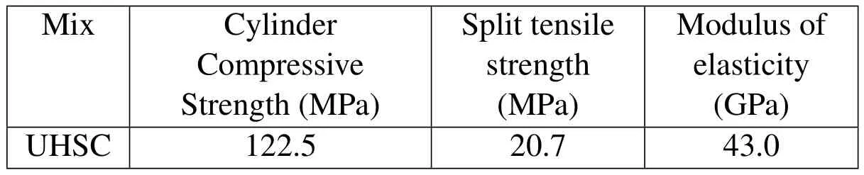
Table 2:Mechanical properties of UHSC.

Figure 1:Typical stress-strain behaviour of UHSC mix.

Figure 2:Pro file steel sheet used in UHSC sandwich Panel.
Uniaxial tensile test has been conducted on tension coupons of 1.2 mm thick cold worked pro file sheet as per ASTM E-8.Typical stress-strain data obtained from the experiment has been plotted in Figure3.The elastic modulus value obtained from the test is 200 GPa and the Poisson’s ratio is 0.3.
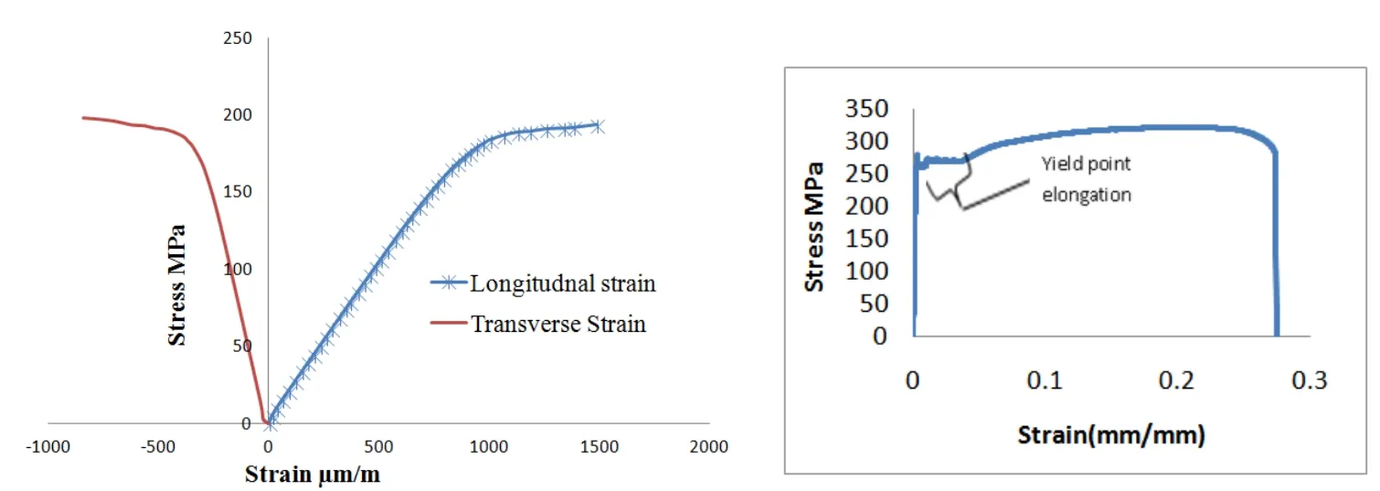
Figure 3:Stress-strain behaviour under uniaxial tensile loading.
4 Self Tapping Screws
From the literature,it is observed that self tapping screws are effective conection in transferring the force(Ramachandra Murthy et al.2013).In the present study,self tapping screws are used to connect prefabricated UHSC bottom skin and pro filed sheet.Typical self-tapping screws are shown in Figure 4.

Figure 4:Typical self tapping screw.
Hat section
Dominant flexural action can be reduced by providing hat section in the trough region of pro file sheet as shown in Figure 5.Further,hat section will reduce the weight of the panel due to the pro file of geometry.
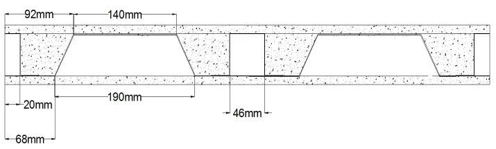
Figure 5:Typical cross-sectional view of UHSC Sandwich Panel with hat section.
5 Fabrication and testing of UHSC Sandwich panel
UHSC sandwich panel consists of three components,namely,bottom skin(precast),pro file sheet and top skin(Cast-in-situ).Bottom panel is cast first and after sufficient curing,it has been attached to a pro filed sheet and hat section using self tapping screws.
The dimensions of the bottom skin are 1500x650x10mm.For all the panels,a pro filed steel sheet of size 650x 1500x1.2mm has been used as a core material between the top and bottom skins.UHSC mix proportion is shown in Table 1.Figure 6 shows the typical casting process of UHSC sandwich panel.The connection between skin and core has been provided with self-tapping screws of 4mm diameter at 150mm spacing.After fixing of pro file sheet and hat section with prefabricated bottom panel,top part of UHSC has been cast and is shown in Figure6.The total thickness of sandwich panel is about 70mm.
Sandwich panel has been cured using moist sand bed and gunny bag for 28 days.The experiment has been carried out using a loading frame which is a Material Testing System(MTS).Figure 7 shows a typical experimental setup.The loading frame is connected to a Data Acquisition System which interprets the data obtained from Strain Gauges and Linear Variable Displacement Transducer(LVDT).Three LVDTs are placed,at the bottom of the panel,at three locations,near the mid-span.The displacements at different loads are recorded in the data acquisition system.All the panels have been tested under simply supported conditions.The effective span of the panels are kept as 1170mm with middle 390mm for constant bending moment zone.By using material testing system,load is applied through hydraulic jack as equally distributed line loads at 390mm from the supports.The Specimens are tested under displacement rate of 1mm/min.
The flexural performance of UHSC steel sandwich panels have been carried out in two ways by applying the load on the top face of cast-in-situ UHSC skin.
Various stages of crack propagation are shown in Figure 7.

Figure 6:Fabrication of UHSC sandwich panel.
During the experiment,the first crack is observed in bottom region of sandwich panel in the range of 4-5 kN load.The crack is through-through crack bridging across the entire width of the section as shown in Figure 8.After first crack,there is reduction in the stiffness of the panel and with increasing the load,multiple crack started forming on the bottom panel which shows the redistribution of stresses.Crack widening is increasing as load transferred from bottom panel to flange of pro file sheet.From the experimental investigations of UHSC panel,it is observed that the ultimate load taken by panel is 42.5kN and the maximum displacement is 43mm.Predominant crack propagation along width of the panel is observed on the bottom face of the panel before final failure of UHSC panel.The experiment has been stopped due to safety condition in the experimental setup.The load vs displacement behavior of UHSC panel is shown in Figure 9.It can be noted that the sandwich panel exhibits large deformation without signi ficant load drop which indicates larger ductility and energy absorption.For larger loads,shear failure of screws has been observed.
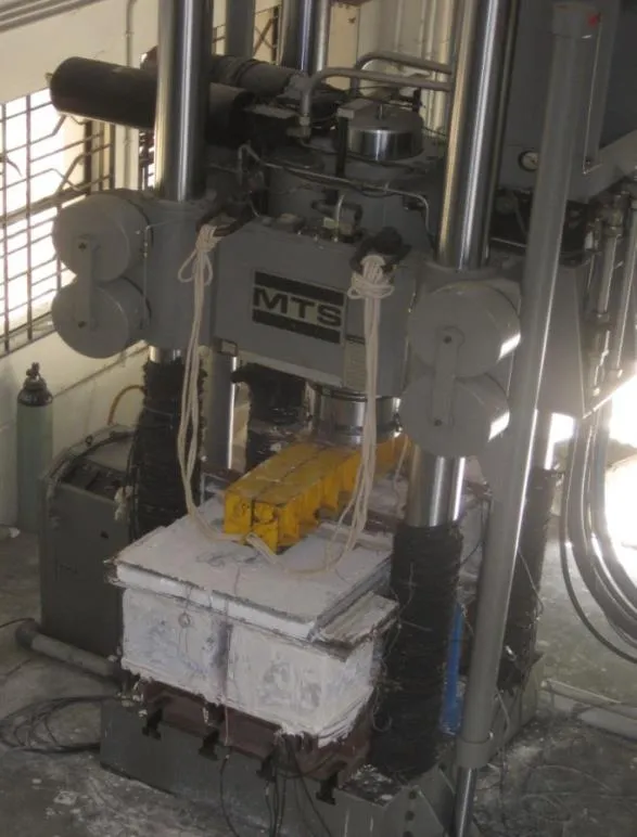
Figure 7:Typical experimental set up.

Figure 8(a):Initiation of the crack in the bottom UHPC.

Figure 8(b):Growth of Crack along the midspan.

Figure 8(c):Failure of Bottom the midspan UHPC Panel.

Figure 9:Load vs deformation at centre(case I).
6 Finite Element Analysis
Finite element analysis of UHSC sandwich panel has been has been carried out by using general purpose finite element software,ABAQUS(2010).There are several challenges in terms of simulating the real experimental behaviour of UHSC sandwich panel.The challenges include(i)modelling of bottom panel(ii)modelling of pro file sheet(iii)modelling of self tapping screws(iv)connection of self tapping screws with the bottom plate and pro filed sheet(v)modelling of top panel(vi)simulation of boundary conditions(vii)proper load application(viii)de fining failure criterion(ix)selection of appropriate material model and corresponding input parameters and(ix)appropriate element selection and solution
Concrete damage plasticity model has been employed to represent the nonlinearity of concrete.Fracture energy has been used as one of the parameters to de fine the cracking of concrete and the value has been taken from literature[Lue et al.(2010)].As far as possible,experimental conditions have been simulated in the numerical modelling.Nonlinear behaviour of pro file steel sheet has been accounted for in the modelling.Tie constraint is given at two levels:(i)interaction between Hat Section and steel core and(ii)interaction between Hat Section-steel core and top and bottom UHSC skins.The element employed for each part is C3D8R:A 8-noded linear brick,reduced integration,hourglass control.But the mesh size is different for different parts.The mesh size provided for the pro file sheets is 85,the steel core it’s 80 and the hat section it is 5.Static nonlinear analysis has been carried out.Stress strain curve of UHSC and pro filed sheet have been used for analysis.Typical deformation of UHSC sandwich panel is shown in Figure 10.The deformation obtained at the centre of the panel is compared with the corresponding experimental result.Figure 11 presents the comparison of deformation obtained from experiment as well as numerically for various loads.It can be noted from Figure 11 that the behaviour predicted using ABAQUS is reasonably in good agreement with that of experimental value.The post peak deformation of sandwich panel could not be predicted accurately due to the improper modelling of connection i.e the failure phenomenon of self tapping screws are not accounted properly in the modelling.

Figure 10:Typical deformation contour.
7 Summary and Conclusion
A novel sandwich panel composed of ultra high strength concrete(UHSC)as top and bottom skin and cold formed steel(pro filed sheet)as sandwich has been proposed.Bottom skin of UHSC is precast in nature where as top skin is cast-in-situ.The connection between top skin of UHSC and cold formed steel is made with self tapping screws.The flexural performance of UHSC steel sandwich panels have been carried out by applying the load on the face of cast-in-situ UHSC skin.It is noted that the sandwich panel exhibits large deformation without significant load drop which indicates larger ductility and energy absorption.It is observed that l the failure of the specimen is occurred by forming a dominant crack on the bottom face of the skin apart from formation of many multiple cracks with increase of load.Numerical investigations have been carried out by simulating the exper-imental conditions and found that the response obtained through simulation is in good agreement with the corresponding experimental values.From the studies,it can be concluded that UHSC steel sandwich panels can be employed for structural and non structural applications.

Figure 11:Comparison of load vs deformation.
Acknowledgement:The authors thank the staff of the Computational Structural Mechanics Group and Advances Materials Laboratory of CSIR-SERC for the cooperation and suggestions provided during the investigations.This paper is being published with the kind permission of the Director,CSIR-SERC.
Basunbul,I.A.,Saleem,M.;Al-Sulaimani,G.J.(1991):Flexural behavior of ferrocement sandwich panels.Cement and Concrete Composites,vol.13,no.1,pp.21–28.
Benayoune,A.;Samad,A.A.;Trikha,D.N.;Ali,A.A.;Ellinna,S.H.M.(2008):Flexural behaviour of pre-cast concrete sandwich composite panel–Experimental and theoretical investigations.Construction and Building Materials,vol.22,no.4,pp.580–592.
Flores-Johnson,E.A.;Li,Q.M.(2012):Structural behaviour of composite sandwich panels with plain and fibre-reinforced foamed concrete cores and corrugated steel faces.Composite Structures,vol.94,no.5,pp.1555–1563.
Gopinath,S.;Kumar,V.R.;Sheth,H.;Murthy,A.R.;Iyer,N.R.(2014):Prefabricated Sandwich Panels using Cold Form Steel and Textile Reinforced Concrete.Construction and Building Materials,vol.64,pp.54-59.
Hibbitt,D.;Karlsson,B.;Sorensen,P.(2010):ABAQUS analysis user’s manual(Version 6.10).
Islam,M.M.;Aravinthan,T.(2010):Behaviour of structural fibre composite sandwich panels under point load and uniformly distributed load.Composite Structures,vol.93,no.1,pp.206–215.
Lameiras,R.;Barros,J.;Azenha,M.Isabel,B.(2013):Valente Development of sandwich panels combining fibre reinforced concrete layers and fibre reinforced polymer connectors.PartII:Evaluation of mechanical behaviour.Composite Structures,vol.105,pp.460–470.
Lu,W.;Ma,Z.;Mäkeläinen,P.;Outinen,J.(2012):Behaviour of shear connectors in cold-formed steel sheeting at ambient and elevated temperatures.Thin walled structures,vol.61,pp.229-338.
Murthy,A.R.;Karihaloo,B.L.;Iyer,N.R.;Prasad,B.R.(2013):Determination of size-independent specific fracture energy of concrete mixes by two methods.Cement and concrete research,vol.50,pp.19-25.
Ramachandra Murthy,A.;Iyer,N.R.;Raghu Prasad,B.K.(2013):Evaluation of mechanical properties for high strength and ultra high strength concrete.Advances in Concrete Construction,An International Journal,vol.1,no.4,pp.341-358.
Ramachandra Murthy,A.(2011):Fatigue and fracture behaviour of ultra high strength concrete beams.Ph D thesis,Indian Institute of Science,Bangalore,India.
Shams,A.;Hegger,J.;Horstmann,M.(2014):An analytical model for sandwich panels made of textile-reinforced concrete.Construction and Building Materials,vol.64,pp.451–459.
Sohel,K.M.A.;Liew,J.R.;Yan,J.B.;Zhang,M.H.;Chia,K.S.(2012):Behavior of Steel–Concrete–Steel sandwich structures with lightweight cement composite and novel shear connectors.Composite Structures,vol.94,no.12,pp.3500–3509.
Tarek A.;Moneim,S.(2010):Flexural behaviour of sandwich panels composed of polyurethane core and GFRP skins and ribs.Ph.D Thesis,Queen’s University,Kingston,Ontario,Canada.
