Finite Element Modeling of Compressive Deformation of Super-long Vertically Aligned Carbon Nanotubes
2014-04-14JosephandLu
J.Joseph and Y.C.Lu
1 Introduction
Vertically aligned carbon nanotubes(VACNTs)have been generally synthesized with the aids of various templates.Terrones et al.have grown the first VACNTs by depositing the carbon sources in linear tracks in a silica template[Terrones et al.(1997)].de Heer et al.have made the carbon nanotubes through the use of an aluminum oxide micropore filter,a template used to align the nanotubes[de Heer et al.(1995)].Recently,template-free synthesis has been used to produce the VACNTs[Ishigami et al.(2008);Bajpai et al.(2004);Chen et al.(2010)].In a typical template-free synthesis,hydrocarbon vapor is passed through a high temperature reaction chamber in which a catalyst material has been introduced.Decomposition of hydrocarbon would take place,which leads to the formation/growth of nanotubes.Compared the template synthesis,the template-free synthesis is more effective in producing larger scale and taller nanotubes,so called super-long VACNTs(SL-VACNTs).SL-VACNTs can have the size as large as several square centimeters and the height as tall as several millimeters or centimeters,and have found a wide range of applications in areas such as the electrical interconnects[Kreupl et al.(2002)],thermal interfaces[Cola et al.(2009)],energy dissipation devices[Liu et al.(2008)],and microelectronic devices[Fan et al.(1999)].SL-VACNTs can also be grown on non-planar substrates,i.e.,the rounded carbon fibers.SL-VACNTs on carbon fibers have had significant potentials in aerospace and space applications.They have added multi-functionality to traditional composites[Baur and Silverman(2007);Ci et al.(2008);Zhang et al.(2009)],improved the fiber-matrix interface strength[Sager et al.(2009);Patton et al.(2009)],and used as flow or pressure sensors on micro air vehicles[Zhang et al.(2010)].
Compared to the template grown VACNTs that exhibit discrete structures[Li et al.(1999);Joseph and Lu(2013)],the template-free grown SL-VACNTs are more continuum type materials(Figure 1).The mechanical properties and deformation behaviors of the super-long VACNTshave been investigated experimentally,mostly through the various nanomechanical tests[Mesarovic et al.(2007);McCarter et al.(2006);Pathak et al.(2009);Patton et al.(2009)].To measure the elastic response of the SL-VACNTs,an indenter of either three-face pyramidal shape(Berkovich indenter)or parabolic shape(spherical indenter)has been used to compress the specimen and then withdrawn from it.The indentation load-depth curves are obtained and then analyzed following the standard Oliver-Pharr method[Oliver and Pharr(1992)].The modulus and hardness of the SL-VACNTs have been obtained.In contrast with the extensive experimental work,little analytical or computational effort has been given towards the study of such SL-VACNTs,partially due to their complex microstructures.This paper presents the modeling of SL-VACNTs by using continuum mechanics approach.The SL-VACNTs were treated as foam-like materials and modeled using continuum solid finite elements.
2 Procedures
2.1 Experimental
The present SL-VACNTs were synthesized by low pressure chemical vapor deposition of acetylene on planar SiO2/Si wafers.The catalyst coated wafers were placed inside the quartz tube furnace at 750°C.The pressure in the furnace chamber was maintained at 10 mTorr.The growths of the nanotube arrays were achieved by flowing a mixture gases of 48%Ar,28%H2,24%C2H2at 750°C for 10-20 min.The mechanical behaviors of the SL-VACNTs were characterized in compression mode,with an in-situ nanoindenter equipped inside the scanning electron microscope(SEM).The indenter used was a 100µm diameter flat-faced cylinder,with a polished contact face.The cylindrical indenter was attached to a strain-gage based load cell,which was connected in series to a piezoelectric actuator.The piezoelectric actuator provided displacement control with sub-nanometer resolution.Resultant forces were measured through the load cell.Load and displacement data were recorded and used to compute the stress and strain.During the test,high resolution SEM images were acquired between displacement intervals,which allowed for observing the deformation of the SL-VACNTs under compression.
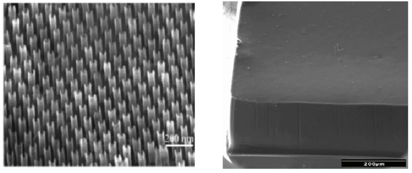
Figure 1:(Left)Template grown vertically aligned carbon nanotubes and(Right)template-free grown super-long vertically aligned carbon nanotubes.
Finite element modeling
The mechanical responses and deformation process of the SL-VACNTs were simulated using the finite element method,in which the SL-VACNTs were treated as continuum solids.The commercial nonlinear finite element(FE)code ABAQUS was used(ABAQUS,2012).The specimen was modeled with second order,8-node axisymmetric elements and the indenter modeled with rigid surface.The contact between specimen and indenter was treated as frictionless.The base of the specimen was completely constrained while the nodes along the center line constrained in the horizontal direction.A vertical described displacement was applied to the rigid surface through a reference node and the reactant force was calculated.
The SL-VACNTs were treated as open-cell,foam-like materials and modeled with the foam plasticity model developed by Deshpande and Fleck(Deshpande and Fleck,2000).This model has been implemented in ABAQUS as the crushable foam model,in which the yield functionφis defined by

where the equivalent stressσis given by

whereσMisesis von Mises effective stress and P is the pressure stress.αis the shape factor of the yield surface,which can be calibrated by using the experimental stress-strain responses of the SL-VACNTs.In the limitα=0 in Equation(1),σreduces toσMises,the conventional von Mises yield criterion.The symbol Y in Equation(1)refers to the uniaxial yield strength in tension or compression.
The Arbitrary Lagrangian-Eulerian(ALE)adaptive meshing technique was used to deal with the severe distortion of elements which occurred in the large displacement indentation.The ALE method was used to allow the mesh to move independently of the underlying material during the simulated penetration,and thus prevent the analysis from terminating as a result of severe mesh distortion.These adaptive meshing procedures have been used for simulating the super plastic forming of metals as well as the explosive deformation of materials under blast loading,which involve large amount of noncoverable deformation[Gakwaya et al.(2011);Voyiadjis and Foroozesh(1991);Souli et al.(2012)].
For comparative purpose,the indentation process of a dense solid was also modeled.The solid was treated as a power-law work-hardening,elastic-plastic solid,as described in detail elsewhere[Lu and Shinozaki(2008)].The constitutive behavior of the power-law work-hardening,elastic-plastic solid were modeled as a piecewise linear/power-law hardening relation
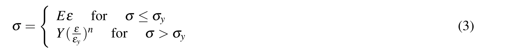
where “σ”and “ε”were the applied stress and strain;“Y”and “εy”the material yield stress and strain; “E”the Young’s modulus;and “n”the strain hardening exponent describing the post-yield material behavior as a power law relation.The plasticity was modeled by a standard von Mises(J2)flow criterion.
3 Results and discussion
3.1 Stress-strain Responses of SL-VACNTs
Figure 2 shows the stress-strain response of the super-long,vertically aligned carbon nanotubes through compression test and finite element simulation.The calculated stress-strain curve is similar to the one measured in the experiment.Results reveal that the material initially deforms elastically with the applied load on the compression platen(indenter),and yields at some point as the applied load is increased.The plateau region indicates the plastic collapses of carbon nanotubes beneath the indenter face.Such collapse allows the strain increase while the stress stays approximately constant.A series of“load-drop”in the plateau regions is observed,which corresponds to the folding of additional carbon nanotubes.
The uniaxial yield strength,or the critical bucking stress,Y,is determined by extrapolating the stress-strain curve back to zero displacement(d=0).The magnitude of Y so obtained for the present SL-VACNTs is approximately 6.2 MPa.
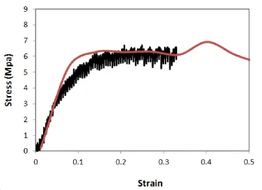
Figure 2:Compressive stress-strain response of the super-long SL-VACNTs(height≈1100µm)obtained from experiment and finite element simulation.
3.2 Deformation of Super-long SL-VACNTs

It is observed that the stress distribution of SL-VACNTSs under compression is distinctly different from that of solid polymers.For a dense,solid polymer,the distribution of the stress(σ1)under the flat indenter is in a hemi-spherical shape.The size(elastic-plastic boundary)of the stress field approximates the diameter of the indenter(2a),as illustrated by the cavity model described Johnson(1985).In contrast,the stress field(σ1)for the foam-like SL-VACNTSs under the flat indenter is much smaller.The stress is primarily concentrated right beneath the indenter face and does not get extended to far field.

Figure 3:Contours of 1st principle stress under compression:(left)a super-long,vertically aligned carbon nanotubes and(right)a dense,solid material.
Figure 4 shows the compressive deformation of the SL-VACNTs under a flat indenter.The simulation is in close agreement with the experimental observation.The early stage of penetration is dominated by the elastic deformation,as reveled by larger slope in the stress-strain curve(Figure 2).Larger slope indicate that the SL-VACNTs have greater stiffness initially.Further compression of the indenter results in the plastic collapse of the carbon nanotubes beneath the indenter head(Figure 4).The measured stiffness thus decreases with increasing depth of indentation.Observations show that the plastic collapse of the nanotube arrays is limited in extent to the zone directly underneath the indenter face where the principal stress is large(Figure 3).The size of this collapsing zone is much smaller as compared to the typical hemi-spherical shaped plastic zones occurred on dense,solid materials,such as polycarbonate[Wright et al.(1992)]and polyethylene[Lu and Shinozaki(1998)].The nanotubes outside the collapsing zone are seen to exhibit no fracture or tearing.
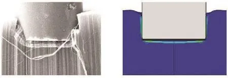
Figure 4:Compressive deformation of SL-VACNTs under a flat indenter obtained from experiment and finite element simulation.

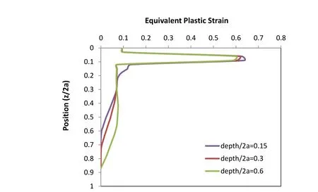
Figure 5:Distributions of equivalent plastic strain(εeq)in SL-VACNTs under various compression depths.
3.3 Effect of Areal Density of CNT arrays
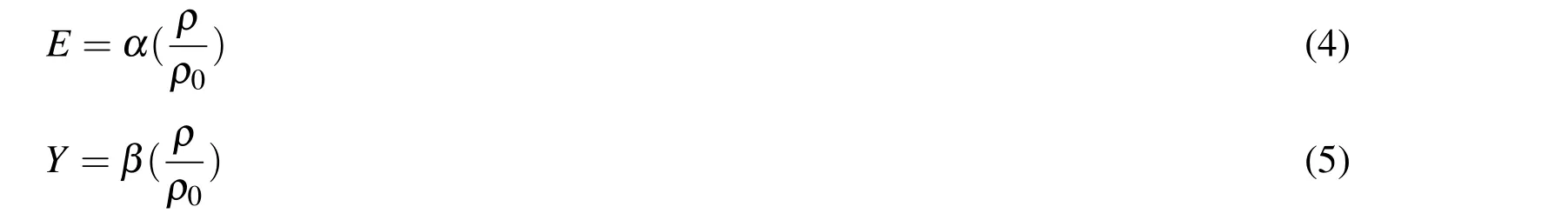
The effect of density on mechanical responses of the foam-like SL-VACNTs is investigated.The SL-VACNT were again treated as open-cell foam materials.According to Gibson and Ashby(1997),the relevant elastic modulus(E)and plastic yield strength(Y)scale with the density(ρ)for the open-cell foams:
whereρ0is the reference density andαandβare scaling coefficients.
In present study,the effect of density was examined by varying the elastic modulus and yield strength of the SL-VACNTs as:E/E0=1,0.8,0.6,0.4 and Y/Y0=1,0.8,0.6,0.4,where E0and Y0are the elastic modulus and yield strength of the original SL-VACNTs.The stress-strain responses of the SL-VACNTs at various density ratios are shown in Figure 6.As the density decreases,the SL-VACNTs become more compliance.
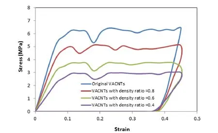
Figure 6:Compressive stress-strain responses of the super-long SL-VACNTs with varying densities obtained from the finite element modeling.
4 Conclusions
The mechanical behaviors of the super-long,vertically aligned carbon nanotubes(SL-VACNTs)have been characterized using compression test and finite element modeling.Both experimental and FE results show that the SL-VACNTs exhibit a transient elastic deformation at small displacement and then steady sate plastic deformation at large displacement.Experiment results and finite element simulations have shown that the sizes of stress/strain zones under the compression platens are much smaller in foam-like SL-VACNTs,as opposed to much larger,hemispherical stress/strain zones observed in the dense solids.Under compression,the nanotube cells collapsed plastically immediately beneath the indenter,a region of the highest stress/strain.The stress-strain responses of the SL-VACNTs are sensitive to the densities of the materials.
Acknowledgement:This work has been supported by the Kentucky NASA EPSCoR RIA program and the Kentucky Science and Engineering Foundation(KSEF)RDE program.
ABAQUS(2012):ABAQUS Theory’Manual,Simulia Inc.,Pawtucket,RI.
Bajpai,V.;Dai,L.;Ohashi,T.(2004):Large-scale synthesis of perpendicularly aligned helical carbon nanotubes.J Am Chem Soc,vol.126:pp.5070-1.
Baur,J.;Silverman,E.(2007):Challenges and opportunities in multifunctional nanocomposite structures.MRS Bulletin,vol.32,pp.328-332.
Chen,H.;Roy,A.;Baek,J.-B.;Zhu,L.;Qu,J.;Dai,L.(2010):Controlled growth and modification of vertically-aligned carbon nanotubes for multifunctional applications.Materials Science and Engineering:R:Reports,vol.70,no.3-6,pp.63-91.
Ci,L.;Suhr,J.;Pushparaj,V.;Zhang,X.;Ajayan,P.M.(2008):Continuous carbon nanotube reinforced composites.Nano Lett,vol.8,no.9,pp.2762-2766.
Cola,B.A.;Xu,J.;Fisher,T.S.(2009):Contact mechanics and thermal conductance of carbon nanotube array interfaces.International Journal of Heat and Mass Transfer,vol.52,no.15-16,pp.3490-3503.
De Heer,W.A.;Bacsa,W.S.;Chatelain,A.;Gerfin,T.;Humphrey-Baker,R.;Forro,L.;Ugarte,D.(1995):Aligned Carbon Nanotube Films:Production and Optical and Electronic Properties.SCIENCE REPORTS,vol.268,no.12,pp.845-847.
Deshpande,V.S.;Fleck,N.A.(2000):Isotropic Constitutive Model for Metallic Foams.Journal of the Mechanics and Physics of Solids,vol.48,pp.1253-1276.
Fan,S.;Chapline,M.G.;Franklin,N.R.;Tombler,T.W.;Cassell,A.M.;Dai,H.(1999):Self-oriented regular arrays of carbon nanotubes and their field emission properties.Science,vol.283,pp.512.
Gakwaya,A.;Sharif i,H.;Guillot,M.;Souli,M.;Erchiqui,F.(2011):ALE Formulation and Simulation Techniques in Integrated Computer Aided Design and Engineering System with Industrial Metal Forming Applications.Computer Modeling in Engineering&Sciences,vol.73,no.3,pp.209-266.
Gibson,L.J.;Ashby,M.F.(1997):Cellular solids,structure and properties,2ndEd,Cambridge University Press,Cambridge,UK.
Ishigami,N.;Ago,H.;Imamoto,K.;Tsuji,M.;Iakoubovskii,K.;Minami,N.(2008):Crystal Plane Dependent Growth of Aligned Single-Walled Carbon Nanotubes on Sapphire.Journal of American Chemistry Society,vol.130,no.30,pp.9918-0024.
Johnson,K.L.(1985):Contact Mechanics,Cambridge University Press,Cambridge.
Joseph,J.;Lu,Y.C.(2013):Design of Aligned Carbon Nanotubes Structures Using Structural Mechanics Modeling Part 2:Aligned Carbon Nanotubes Structure Modeling.CMC:Computers,Materials&Continua,vol.37,no.1,pp.59-75.
Kreupl,F.;Graham,A.P.;Duesberg,G.S.;Steinhögl,W.;Liebau,M.;Unger,E.;Hönlein,W.(2002):Carbon Nanotubes for Interconnect Applications.Microelectronic Engineering,vol.64,no.1-4,pp.399-408.
Liu,Y.;Qian,W.Z.;Zhang,Q.;Cao,A.Y.;Li,Z.F.;Zhou,W.P.;Ma,Y.;Wei,F.(2008):Hierarchical agglomerates of carbon nanotubes as high-pressure cushions.Nano Letters,vol.8,pp.1323.
Li,J.;Papadopoulos,C.;Xu,J.;Moskovits,M.(1999):Highly-ordered carbon nanotube arrays for electronics applications.Applied Physics Letters,vol.75,pp.367-369.
Lu,Y.C.;Shinozaki,D.M.(1998):Deep penetration microindentation testing of high density polyethylene.Material Sciences and Engineering,A,vol.249,pp.134-144.
Lu,Y.C.;Shinozaki,D.M.(2008):Characterization and modeling of large displacement micro-/nano-indentation of polymeric solids.ASME Journal of Engineering Materials and Technology,vol.130,pp.041001-1.
McCarter,C.M.;Richards,R.F.;Mesarovic,S.Dj.;Richards,C.D.;Bahr,D.F.;McClain,D.;Jiao,J.(2006):Mechanical compliance of photolithographically defined vertically aligned carbon nanotube turf.Journal of Materials Science,vol.41,pp.7872-7878.
Mesarovic,S.D.;McCarter,C.M.;Bahr,D.F.;Radhakrishnan,H.;Richards,R.F.;Richards,C.D.;McClain,D.;Jiao,J.(2007):Mechanical behavior of a carbon nanotube turf.Scripta Materialia,vol.56,pp.157-160.
Mesarovic,S.D.;Fleck,N.A.(1987):Spherical indentation of elastic-plastic solids.Proceedings of Royal Society of London,vol.455,pp.2707-2728.
Oliver,W.C.;Pharr,G.M.(1992):An improved technique for determining hardness and elastic modulus using load and displacement sensing indentation experiments.Journal of Materials Research,vol.7,pp.1564.
Pathak,S.;Cambaz,Z.G.;Kalidindi,S.R.;Swadener,J.G.;Gogotsi,Y.(2009):Viscoelasticity and high buckling stress of dense carbon nanotube brushes.Carbon,vol.47,no.8,pp.1969-1976.
Patton,S.T.;Zhang,Q.;Qu,L.;Dai.L.;Voevodin,A.A.;Baur,J.(2009):Electromechanical characterization of carbon nanotube grown on carbon fibers.Journal of Applied Physics,vol.106,pp.104313.
Sager,R.J.;Klein,P.J.;Lagoudas,D.C.;Zhang,Q.;Liu,J.;Dai,L.;Baur,J.W.(2009):Effect of carbon nanotubes on the interfacial shear strength of T650 carbon fiber in an epoxy matrix.Composites Science and Technology,vol.69,no.7-8,pp.898-904.
Souli,M.;Bouamoul,A.;Nguyen-Dang,T.V.(2012):ALE Formulation with Explosive Mass Scaling for Blast Loading:Experimental and Numerical Investigation.Computer Modeling in Engineering&Sciences,vol.86,no.5,pp.469-486.
Terrones,M.;Grobert,N.;Olivares,J.;Zhang,J.;Terrones,P.H.;Kordatos,K.;Hsu,W.K.;Hare,J.P.;Townsend,P.D.;Prassides,K.;Cheetham,A.K.;Kroto,H.W.;Walton,D.R.M.(1997):Controlled production of alignednanotube bundles.Nature,vol.388,no.3,pp.52-55.
Voyiadjis,G.Z.;Foroozesh,M.(1991):A finite strain,total Lagrangian finite element solution for metal extrusion problems.Computer Methods in Applied Mechanics and Engineering,vol.86,no.3,pp.337-370.
Wright,S.C.;Huang,Y.;Fleck,N.A.(1992):Deep Penetration of Polycarbonate by a Cylindrical Punch.Mechanics of Materials,vol.13,pp.277.
Zhang,Q.;Liu,J.;Sager,R.;Dai,L.;Baur,J.(2009):Hierarchical composites of carbon nanotubes on carbon fiber:Influence of growth condition on fiber tensile properties.Composites Science and Technology,vol.69,no.5,pp.594-601.
Zhang,Q.;Lu,Y.C.;Du,F.;Dai,L.;Baur,J.;Foster,D.C.(2010):Viscoelastic creep of vertically aligned carbon nanotubes.Journal of Physics,D:Applied Physics,vol.43,315401.
杂志排行

Computers Materials&Continua的其它文章
- High Velocity Impact Behaviour of Layered Steel Fibre Reinforced Cementitious Composite(SFRCC)Panels
- Generalized Rayleigh Wave Dispersion Analysis in a Pre-stressed Elastic Stratified Half-space with Imperfectly Bonded Interfaces
- Investigation of the Embedded Element Technique for Modelling Wavy CNT Composites