Investigation of the Embedded Element Technique for Modelling Wavy CNT Composites
2014-04-14AnnaMatveevaHelmuthmGrygoriyKravchenkoandFerrievanHattum
Anna Y.Matveeva,Helmut J.Böhm,Grygoriy Kravchenko and Ferrie W.J.van Hattum
1 Introduction
The mechanics of nanocomposite materials is highly complex,consideration of a number of different length scales being required for obtaining a solid understanding.Modelling approaches based on the Molecular Dynamics simulations are too expensive computationally and are limited to nanoscales.With an appropriate linking between computational chemistry and solid mechanics,structure-property relationships in nanocomposites can be analysed on micro/meso/macro-length scales.Odegard[Odegard,Pipes and Hubert(2004);Odegard,(2002)]replaced discrete molecular structures with equivalent-continuum models,therefore representing the nanoscale interactions between polymer and nanoparticles and in the same time determining continuum effective properties for the composite.A review of similar methodologies applicable to a hierarchical approach to modelling the macroscopic behaviour of nanostructured materials can be found in[Buryachenko,Roy,Lafdi,Anderson and Chellapilla(2005)].Due to the relative simplicity of the micromechanical models,they provide the ability to assess the key factors,.e.g.volume fraction,orientation,diameter and length distributions,controlling the effective elastic behaviour.For such modelling approaches,accounting for the twisted,tangled and clustered geometries of the reinforcements has proven to be a difficult issue.Continuum-based modelling approaches,typically based on the Finite Element Method(FEM),are more suitable for studying the interactions in arrangements of a number of reinforcing nanoparticles or nanotubes that are embedded in the matrix material[Bhuiyan,Pucha,Worthy,Karevan and Kalaitzidou(2013);Spanos and Kontsos(2008);Pantano,Modica and Cappello(2008)].
To characterize the CNTs’waviness,orientation,length and diameter distributions AFM,TEM or SEM techniques can be utilised.One of the methodologies for determining the straightness of CNT comes from experimental investigations of collagen waviness and orientation[Rezakhaniha,Agianniotis,Schrauwen,Griffa,Sage,Bouten,Vosse,Unser,Stergiopulos(2012)].Spatial distributions of nanoparticles and their dispersion can be obtained with light optical microscopy techniques[Pegel,Villmow and Pötschke(2011);Brooker,Guild,and Taylor(2011)].In principle,this information allows setting up synthetic volume elements that satisfactorily describe such microgeometries.However,the geometrical complexity of the resulting volume meshes taxes standard approaches to FEM-based micromechanical models,in which all phase regions are discretized by volume elements,the meshes of the phase boundary surfaces being identical in matrix and reinforcement.Detailed models obtained this way are expensive in terms of computational resources and manpower.Accordingly,simplified procedures are of considerable practical interest.One such approach showing considerable potential are superposition techniques in which matrix and reinforcements are discretized independently and tied together by suitable constraint equations to make up the full model.Embedding options are typically available in major finite element codes,e.g.,for modelling rebars.Checking the suitability of such techniques for handling the curved fibre geometries prevalent in nanocomposites is the main goal of the present contribution.
Numerical and experimental investigations of microgeometrical parameters such as orientation[Lusti and Gusev(2004);Pujari,Rahatekar,Gilman,Koziol,Win-dle and Burghardt(2009)],aspect ratio[Martone,Faiella,Antonucci,Giordano,Zarrelli(2011);Thostenson and Chou(2003);Wang,Liang,Wang,Zhang(2006)],concentration,agglomeration[Pegel,Pötschke,Petzold,Alig,Dudkin,Lellinger(2008);Song and Youn(2005);Shi,Feng,Huang,Hwang and Gao(2004);de Villoria and Miravete(2007)],waviness[Bradshaw(2003);Fisher(2003);Joshi,Sharma and Harsha(2011);Karami and Garnich(2005)],etc.of carbon nanotubes(CNT)are available in the literature.It was found that waviness and CNT agglomeration are among the strongest factors determining the mechanical behaviour of polymeric nanocomposites.At present,accounting for the complex,three-dimensional arrangements of CNTs evident in TEM/SEM images remains an unsolved issue.In previous work of the authors[Matveeva,Pyrlin,Ramos,Böhm,van Hattum(2014)]it was shown that for very small reinforcement volume fractions,wavy and curly nanotubes meshed with beam elements,which are embedded in a matrix discretized with continuum elements,can provide essentially the same mechanical responses as do “classical”(or,in the parlance of[Tabatabaei,Lomov and Verpoest(2014)],“full”)FE models in which both constituents are meshed compatibly with 3D solid elements.In this dilute regime good agreement was also obtained with MD simulations of a polycarbonate matrix reinforced with curved single-walled nanotubes.
The models used in[Matveeva,Pyrlin,Ramos,Böhm,van Hattum(2014)]are related to the domain superposition technique(DST)introduced by Jiang[Jiang,Hallett and Wisnom(2008)]for simplifying the discretisation of 3D models of woven fabric composites.In the DST the phase regions are meshed separately,the inhomogeneity mesh is embedded in the matrix mesh,and the two meshes are linked by suitable coupling equations.To counteract effects of the geometrical overlapping between inhomogeneites and matrix,the material properties used for the latter are chosen as the excess stiffness of the fibres compared to the matrix.This concept has been extended to nonlinear matrix behaviour[Jiang(2012)],whereas Biragoni and Hallett[Biragoni and Hallett(2009)]reported employing such a technique for evaluating the full stiffness tensors of weaves.
Tabatabaei[Tabatabaei,Lomov and Verpoest(2014)]used a DST-like method that applies the “embedded element”(EE)constraints available in the FE package ABA QUS to the mesoscopic-FEM analysis of fibre reinforced composites.A quantitative assessment of the differences in the stress fields and macroscopic stiffness tensors predicted by the full and EE models was presented and good correlation was reported for several case studies:a single cylindrical carbon fibre,irregularly distributed unidirectional carbon fibres,a single crimped yarn with carbon fibres as filaments inside a polymeric matrix,and a 5H satin reinforced composite.Their approach,in which both matrix and fibres are modelled by volume elements,ap-pears applicable to arbitrarily curved nanotubes,too.However,meshing thousands of nanotubes of high aspect ratio with 3D solid elements and coupling them with the matrix tends to constitute a rather complex task[Romanov,Lomov,Verpoest and Gorbatikh(2014)].
Methods that use beam elements for studying the mechanical responses of CNT based composites can significantly reduce computational cost.Gorski[Gorski(2011)]combined beam Finite Elements for representing straight or sinusoidally curved,parallel nanotubes with a matrix described by a Boundary Element method,the resulting two-dimensional models requiring no embedding.Harper[Harper,Qian,Turner,Li,Warrior(2012)]applied beam elements embedded into a matrix to investigating volume elements of composites reinforced with discontinues straight carbon fibres,also in two dimensions.
Johnson[Johnson(2013)]modelled arrays of vertically aligned carbon nanotubes,individual CNTs being meshed with linear or quadratic shell elements.In a convergence study of the Young’s modulus,quadratic 8-node elements showed the most consistent behaviour upon increasing the numbers of nodes and elements.Ghasemi[Ghasemi,Rafiee,Zhuang,Muthu and Rabczuk(2014)]investigated the influence of discretisation and approximation errors on the macroscopic behaviour for one type of shell element.
The present work aims at providing quantitative comparisons between predictions for the homogenized behaviour of a polymer matrix reinforced by curved nanotubes when the latter are discretized by beam,shell or solid elements that are coupled to the matrix by multi-point constrains.Solid models with conventionally meshed matrix and fibres are used for providing reference data,different phase volume fractions and levels of fibre waviness being considered.
2 Case studies
The motivation for this work comes from studying CNT based composites.Carbon nanotubes can show straight,twisted,or curved shapes,can be either single-walled or multi-walled,can have different radii and lengths,and may have a wide range of orientation and spatial distributions in the matrix.All these factors complicate simulations of the effective mechanical responses of CNT composites.The concepts of statistical and representative volume elements allow investigating these parameters one by one or in groups by choosing appropriate unit cells.In this work,periodic arrangements of hollow Multi-Walled Carbon Nanotubes(MWCNT)embedded in a polymeric matrix are modelled by unit cells containing one CNT or a square arrangement of CNTs and applying proper boundary conditions.The nanotubes are assumed to show a ratio of 2 between outer and inner diameters and infinite length(for comparison,amino-modified Multi-Walled Carbon Nanotubes(MWCNTs-NH2)were found to have an outside diameter of 8-15 nm,an inside diameter of 3-5 nm and an average length of 50 um1http://www.nanoamor-europe.com/nanomaterials/carbon-nanotubes-nanofibers/carbonnanofibers-special-cnts/amino-modified-mwnts/mwnt-nh2-1562yjf.html).Following Eq.(1)nanotubes are represented as sine-like fibres of various amplitudes described by the parametric equation

Here,Astands for the amplitude andHfor the wave length of the sine.Such shapes may be described by a waviness parameter defined asw=A/H.
Several configurations are considered,which are characterised by different values of the waviness parameter,the radii of the CNT and the reinforcement volume fraction.Differen
t ways of discretising CNT and matrix are compared in each case in order to elucidate trade-offs and identify approaches suitable for modelling composites reinforced by curved fibres at good accuracy and low cost.
The first case study concentrates on single,wavy,hollow nanotubes which are not embedded in a matrix and are subjected to tensile loading.The aim is to analyse the influence of different values of slenderness of the tubes on models utilizing beam,shell,or solid elements.Since models of this type do not have an absolute length scale,actual units of length do not play a role.The waviness parameter was maintained at a value ofw=0.125,the wavelength being 2 length units,as stated in Eq.(1),and the amplitude 0.25 units.Outer radii of 0.08,0.12,0.16 and 0.2 units were used for varying the tubes’slenderness,the inner radii taking half these values.The material properties are listed in Tab 1.

Table 1:Material properties used for simulations.
Er,Em,vrandvmbeing the Young’s moduli and Poisson coefficients of the reinforcement and matrix phases,respectively.
The models of the second case study are wavy,hollow nanotubes embedded in matrix material,the cube-shaped volume elements having an edge length of two units,which also equals the wavelength of the tubes’curviness.Constant outer and inner radii,RCNT=0.04 andrCNT=0.02,are considered,the amplitude of the sine being varied to give waviness parameters of 0.08,0.125,0.2.For the superposition models the nanotubes were meshed with solid,shell and beam elements and multi-point constraints were used to embed the reinforcements in the matrix.In addition,conventional,“full”3D solid models were created for providing reference solutions.Different fibre volume fractions were obtained by changing the number of nanotubes within the unit cell,1,2,4 or 16 nanotubes being arranged evenly in a square pattern,see Tab.2.For straight nanotubes(waviness parameter of 0.),different volume fractions were obtained by changing radii of nanotubes,see Tab.3.The reinforcement volume fraction was evaluated as

whereNis the number of nanotubes in the unit cell andAcellstands for the crosssectional area of the unit cell transverse to the nanotube axis.In actual nanocomposites,the polymer matrix does not penetrate to the CNTs and an interphase layer is present.The thickness of this interphase layer may be approximated by half the equilibrium van der Waals separation distance between CNT and matrix,and subsumed into the fibre volume,compare Han and Elliot[Han and Elliot,(2007)].Such a model would require adapting the nanotubes’stiffness to include interphase contributions and is not used in the present work.

Table 2:Values of volume fraction c r and waviness parameter w covered in the present study for wavy fibres(R CNT=0.04).
The material parameters used for the simulations are presented in Tab.1.The approach of assigning material parameters corresponding to the difference between the elasticity tensors of nanotubes and matrix-as proposed in Jiang[Jiang,Hallett and Wisnom(2008);Jiang(2012)]is not followed in the present work because its consistent extension to the bending and torsion stiffnesses associated with the rotational degrees of freedom of beam and shell elements does not appear feasible.Detailed discussions of experimental findings as well as theoretical and computational models for the mechanical properties of carbon nanotubes can be found in[Yakobson and Avouris(2001)].A wide range of Young’s moduli have been reported for different types of CNTs,which is partly due to the presence of dislocations,voids,point defects,etc.Young’s moduli obtained by experimental investigations of MWCNT produced by the CVD method varied from 10 GPa to 450 GPa for ordered and disordered multi-walled carbon nanotubes[Salvetat,Kulik,Bonard,Andrew,Briggs,Stockli,Méténier,Bonnamy,Béguin and Forro(1999);Xie,Li,Pan,Chang and Sun(2000)].For the present work,a value ofEr=400 GPa is chosen for describing the material behaviour of MWCNTs modelled as isotropic hollow tubes.In future work anisotropic properties of CNT may be used,e.g.,by following the approach of Papanikos[Papanikos,Nikolopoulos and Tserpes(2008)],who evaluated the equivalent properties of beams by relating the tensile,bending and torsional stiffness with the chiral number of nanotubes.
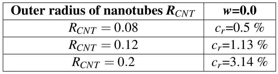
Table 3:Values of volume fraction c r for straight nanotubes.
3 Finite Element Model
The FE code ABAQUS/Standard(3DS,Dassault Systèmes,Waltham,MA)and the associated pre-processor ABAQUS/CAE were used for numerically computing the effective elastic properties for the two case studies described above.
The nanotubes in case study 1 were modelled as hollow wavy tubes of fixed wavelength and amplitude but different radii,beam,shell and solid elements being used to discretize them.Three-node Timoshenko beam elements(ABAQUS element B32)and Mindlin-Reissner thick shell elements with quadratic interpolation(S8R)were chosen to handle transverse shear flexibility,the outer surface of the nanotubes being used as the reference surface in the latter case.Both shells and beams carry transverse loads by bending or shearing action;the main difference in their behaviours being due to the shells’better capabilities of modelling changes in tube cross section.Quadratic brick elements(C3D20)were chosen for the solid models as they are known to be the best elements for linear elastic calculations[Zienkiewicz(2013)].
The single sine-like hollow nanotubes investigated in case study 1,compare Fig.3,were solely loaded in their longitudinalx-direction and fixed on one end by suitable boundary conditions:
For fibres meshed with beam elements,all translational degrees of freedom of the node on the “back face”(x=0)and the translational degree of freedom inz-direction of the node on the “front face”(x=H)are fixed,with the rotational degrees of freedom of all nodes remaining free.For fibres meshed with shell and solid elements the translational degrees of freedom inx-direction of all nodes on the“back face”are fixed,node(0.,0.,0.)is completely fixed and node(0.,0.,DCNT)is not allowed to move iny-direction.The translational degrees of freedom in longitudinalx-direction of all nodes on the“front face”are constrained to the corresponding degree of freedom of node(H,0.,0.),which is loaded in longitudinalx-direction.Here,Hstands for the wave length of the sine andDCNTfor the diameter of the nanotube.Additionally,node(H,0.,0.)is fixed iny-andz-directions.The rotational degrees of freedom of the shell elements remained free.With such boundary conditions the fibres are prevented from twisting and the cross section is allowed to change.
Results for wavy tubes(w=0.125)of different radius were evaluated in terms of the longitudinal stiffnessk,which takes the form

where,Fis the force applied to the body andu1is the computed displacement along the first degree of freedom.
In case study 2 infinitely long,hollow,wavy tubes perfectly bonded within a matrix material were modelled by unit cells containing one wavelength of the fibres,see Fig.1.
In the “full”three-dimensional finite element model,where both fibres and matrix are described by solid elements,quadratic 20-node brick elements(C3D20)were used wherever possible and 15-node quadratic triangular prism elements(C3D15)were inserted where required by the automatic hexahedral mesher.
For the superposition models a regular,structured mesh of 20-node hexahedra was employed for the matrix.Beam,shell or solid elements were used for independently meshing the nanotubes,which were then embedded in the matrix “host”mesh.The translational degrees of freedom of the embedded nodes are constrained to the interpolated values of the corresponding degrees of freedom of the appropriate host elements,whereas the rotational degrees of freedom of the beam and shell elements are not constrained by the embedding.
This representation of the nanotubes introduces symmetries that support using pe-riodic models.For the purpose of determining the composite’s effective stiffness tensor,periodicity boundary conditions(PBC)are applied in the FE analysis by subjecting pairs of homologous nodes,which occupy corresponding positionsξon pairs of opposite faces of the volume element,to constraint conditions of the type


Figure 1:Sinusoidal fibre meshed with solid elements(“full model”).
Here,uis the displacement vector,0εis a constant strain tensor describing the macroscopic behaviour of the volume element,and∆kξis a constant distance vector between pairs of opposite surfacesk+andk-.For periodic homogenization using the method of macroscopic degrees of freedom[Michel,Moulinec and Suquet(1999)],the macroscopic displacement field within the unit cell is completely defined by the displacements of characteristic vertices,so called master nodes[Pahr and Rammerstorfer(2006)].Node SWB,compare Fig.2,is locked,nodes SEB,NWB and SWT control the macroscopic displacements of the East,North and Top faces,respectively,and the boundary conditions of the other surface nodes follow equation(4),ensuring that opposite face sofa given unit cell deform in a compatible way.
Loading by normal stresses is implemented by applying normal concentrated forces in the 1-,2-and 3-directions to the master nodes SEB,NWB and SWT.In addition,three simple shear load cases are set up by subjecting the master nodes to suitable tangential concentrated forces.Relations between master node forces/displacements and volume average stresses/strains are given in[Pahr and Rammerstorfer(2006)].
The solutions of the above six linearly independent load cases provide six pairs of phase averaged stress and strain tensors.These allow setting up 36 equations,from which the 36 elastic constants making up the macroscopic elasticity tensor can be obtained.The ILSB in-house software Med Tool was used,on the one hand,for generating the boundary conditions and load cases and,on the other hand,for extracting the elastic tensors.
4 Results
The effects of different mesh types,waviness and volume fractions on the effective elastic properties of free and embedded nanotubes are discussed in this section.
4.1 Case study 1:Single nanotube without matrix
The effects of discretization by different element types on the axial displacementsu1and the longitudinal stiffnessk1of free nanotubes are presented in Tab.4.Keeping the wavelength as well as the amplitude,and thus the waviness parameter(w=0.125),of the sine fixed while varying the radii of the nanotubes,these results probe interactions between the slenderness of the fibres and the different discretisations.
Here the applied force wasF=4N.Displacements are given in units of length and stiffness in units of N per unit of length.The wavelength of the sine equals 2 length units,and the error pertains to the axial stiffness,see Eq.(5).
As expected the stiffness increases markedly with increasing tube radius.To assess the efficiency of the different mesh element types,the relative error in stiffness with reference to solid elements is evaluated,


Table 4:Comparison of the stiffness of single,free,sine-like tubes(waviness parameter w=0.125)of different radius,meshed with different types of element.
Compared to the full solid model,both beam and shell models overestimate the axial stiffness for the lower fibre radii considered and underestimate it for the higher radii.The tendency is for the beam models to do better for more slender tubes,and for the shell models for large fibre diameters.One of the reasons for this behaviour lies in the response of the cross sections.Fig.3 presents comparisons between displacements and stress states obtained with solid,beam and shell-models,respectively,pertaining to an outer fibre radius ofRCNT=0.16.Ovalisation of the tubes’cross section is evident for the solid and shell models,but is not included in the beam elements’formulation.This leads to a higher stiffness of the latter models for the case considered.
With decreasing tube radii,the influence of changes to the cross section decreases and the stiffness of the beam model approaches that of the solid model.The shell model,however,is clearly too stiff in this regime.For the simulations in the second case study,a small outer radius is used,RCNT=0.04,for a unit cell length of 2 units.
4.2 Case study 2:Nanotubes embedded in the matrix
This subsection focuses on the assessment of the embedded element technique with different types of mesh element being constrained to the matrix.

Figure 3:Wavy hollow sine-like tubes with a outer fibre radius of R CNT=0.16,meshed with solid(a),beam(b)and shell(c)elements.a1,b1,c1 present longitudinal displacements and a2,b2,c2 distributions of the longitudinal normal stress component,a cut being made with an x=const plane in the middle of the tube.The deformation scale factor is set to 500.
Fig.4 presents comparisons between stress profiles obtained with unit cells containing 4×4 tubes of waviness parameterw=0.125 in a regular,square arrangement for 4 different models(3D solid full model and 3 models with beam,shell and solid elements embedded in the matrix).Part of a longitudinal section of the unit cell,measuring 2×1 length units,is shown.
Generally,the embedding technique captures the stress distribution quite well,though for the model using embedded beams the compressive axial stresses are considerably more strongly concentrated,with small regions showing elevated negative values ofσ11.This is due to the one-dimensional nature of the beam elements,

Figure 4:Distribution of axial normal stress in detail of longitudinal section of arrangement of 16 tubes,w=0.125.
which do not have proper volume and interact with a smaller number of elements in the matrix.The stress distributions predicted by the embedding models using solid and shell elements are quite similar,differences being apparent mainly in the regions of maximum curvature of the tubes.
Quantitative comparisons of the Young’s moduli obtained for models with different waviness parameters are presented in Fig.5.The identifiers”EmbBeam”,”EmbShell”,”EmbSolid”indicate models that use the embedding technique in superimposing matrix and tube meshes,the latter using beam,shell and solid elements,respectively.“Solid”refers to the conventional 3D full solid model.
Different fibre volume fractions were obtained by changing the number of nanotubes within the unit cell for wavy fibres with RCNT=0.04(Tab.2)and by changing the radius for straight fibres(Tab.3).
For straight nanotubes(w=0.0),the linear dependence between volume fraction and axial Young’s modulus is evident and the models give fairly similar results.For the non-zero waviness parameters,the axial Young’s moduli obtained with the superposition method tend to underestimate the results obtained with the full 3D solid model,but are much more efficient in terms of computational and modelling effort.For all cases,the beam models show the softest behaviour,whereas the shell models are considerably closer to the embedded solid models.For waviness parameters ofw=0.125 andw=0.2 the embedded shell predictions give better agreement with the full 3D model results than do the ones generated with the embedded solid model.As expected,waviness can be seen to reduce the effective longitudinal elastic modulus.At a reinforcement volume fraction of 2%a waviness parameter ofw=0.2 is predicted to give rise to a reduction of the Young’s modulus from 8 GPa to 2.8 GPa,which corresponds to a loss of 65%in stiffness.

Figure 5:Longitudinal elastic modulus predicted for fibres with different waviness.
In terms of the longitudinal Young’s modulus,the responses generated with embedded solid and,especially,the embedded shell models in Fig.5 are promising.When comparing these results with the ones obtained in case study 1,a much more favourable behaviour of the shell models is evident.This appears to be due to cancelling out of errors from the discretization of the CNT and from the embedding procedure.
Since the periodic homogenization approach can provide full elastic tensors rather than just the longitudinal Young’s modulus,the influence of the discretization strategy on the other effective elastic constants can also be assessed.When realistic geometries with twisted and tangled CNTs are to be considered,of course,the interactions between fibres and matrix must be described sufficiently well for all local loading conditions,translating into a requirement for good quality approximations for all moduli.Fig.6 shows plots of the relative error in 6 of the 9 elastic moduli relevant to macroscopically orthotropic behaviour.The data is given as functions of the reinforcement volume fraction and the waviness parameters,the fibres having the shape of sine waves in thex-zplane.E11stands for the longitudinal macroscopic Young’s modulus,E22as well asE33for the transverse macroscopic Young’s moduli,G12andG13for the longitudinal andG23for the transverse macroscopic shear moduli of the composite.
Errors in excess of 5%can be seen to occur for the axial Young’s modulus,E11,predicted by the embedded shell models for small waviness parameters and for the longitudinal shear modulus in the plane of waviness,G13,for both solid and shell embedded models at high waviness parameters.In the case of the transverse Young’s modulus,E22,which describes the response normal to the plane of waviness,the errors of both models approach 4%,with the embedded shells being superior for small waviness parameters.For the other moduli the embedded shell approach gives errors of less than 2%and shows a more favourable behaviour than the embedded solid models.
For the whole range of waviness and concentration the beam models show much softer behaviour for all elastic moduli.As example,the relative differences in the predicted 6 elastic moduli between the conventional 3D solid model and the embedded beam model are shown in Tab 5.

Table 5:Relative difference in the predicted six elastic moduli between conventional 3D solid model and embedded beam model.

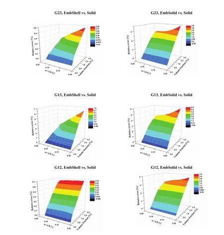
Figure 6:Relative difference in the predicted three Youngs’s moduli and three shear moduli between,on the one hand,the conventional3D solid model and,on the other hand,the embedded shell and embedded solid models,respectively.
The embedding technique is subject to limitations in correctly representing phase volume fractions and total solid volume,the shell and solid elements describing the nanotubes being overlaid on the solids making up the matrix.Thus,corrections by volume fraction must be considered.As mentioned before,this can be achieved for straight nanotubes by assigning the difference between the elasticity tensors of reinforcement and matrix to the latter,compare[Jiang,Hallett and Wis-nom(2008);Jiang(2012)].For beam and shell models describing more complex nanotube geometries,where fiber bending plays an appreciable role,however,this approach requires verification,which is outside the scope of the present contribution.Table 6 shows that overlaying the volumes of matrix and reinforcement does influence the predicted macroscopic moduli.The results labeled“EmbShell model with corrected volume”were obtained by removing the equivalent volume of the nanotubes from the matrix,followed by superposing the fiber mesh and connecting it to the matrix with the standard embedding constraints provided by ABAQUS.The positive sign in the relative difference means that embedded models give stiffer responses than the conventional model.

Table 6:Correction by volume fraction.Relative difference in longitudinal Young’s modulus between embedded beam/shell/solid models and conventional full 3D solid model.
Such volume-corrected shell models,of course,are mainly useful for comparisons,because their use negates most of the advantages in terms of modelling effort that led to studying embedded models in the first place.
5 Conclusions
The performance of composites reinforced by CNT depends strongly on the geometric parameters of the nanotubes,including aspect ratio,waviness,orientation,spatial distribution plus many other factors.Existing quantum mechanical and molecular dynamics methods have only limited applicability to analysing this issue,mainly because the volume elements to be studied are relatively big.The objective of the present work is assessing efficient numerical continuum-level modelling procedures that may be used for studying the mechanical responses of composites reinforced with arbitrarily curved nanotubes at various levels of concentration.Due to computational requirements and difficulties in meshing,the use of conventional full 3D solid models,in which reinforcement and matrix are meshed compatibly with volume elements,is a challenging task.A superposition model is proposed for describing nanotubes embedded into polymer matrices,the nanotubes being meshed separately from the matrix using beam,shell or solid elements and then coupled to the matrix.
For this assessment CNTs are modelled as sine-like hollow tubes or shells with prede fined thickness.Beam and shell models of curved tubes without a matrix are first compared to solid models in order to study the influence of the fibre radius of the individual carbon nanotubes on the choice of element type.It is observed that the predictions for the longitudinal stiffness of single nanotubes in the absence of a matrix are sensitive to the discretisation of tubes.
In a second step nanotubes were meshed independently with beam,shell or solid elements and embedded into a matrix by linking the translational degrees of freedom.Unit cells discretised this way were subjected to 6 linearly independent load cases to evaluate the effective elastic tensor.Results were compared with calculations obtained with conventional 3D full solid models.For all models the effective Young’s and shear moduli increase markedly with increasing reinforcement volume fraction and decrease with increased waviness of the nanotubes.
The relative difference in the Young’s and shear moduli between conventional full solid models and embedded beam/shell/solid models is largest for the beam models,resulting in a much more compliant macroscopic behaviour.In addition,embedded beam models are not very accurate in describing the mechanical responses in the transverse directions and under shear loading,especially at increased volume fraction.
Shell and solid elements are found promising for modelling the effective properties of composites reinforced by carbon nanotubes as they tend to give reasonable values for all considered moduli when compared with the corresponding 3D full models.Overall,embedded shell and embedded solid models exhibit a slightly stiffer longitudinal modulus than the conventional 3D solid model,one of the reason for this being the“doubled”volume in the superimposed models.An interesting fact is that upon increasing the nanotube waviness,the embedded shell model gives more accurate results for the longitudinal elastic modulus compared with embedded solid model.In addition,the embedded shell models give better results than the embedded solid models for the transverse Young’s and shear moduli independently of waviness or volume fraction.
Thus,for the purpose of modelling arbitrarily curved nanotubes,especially when they exhibit strong curvature and have a wide range of orientations,embedding models using shell elements appear to be a promising approach to reducing com-putational effort.
Acknowledgement:The authors would like to acknowledge the support of the Marie Curie Initial Training Network"CONTACT"for the tailored supply-chain development of CNT-filled composites with improved mechanical and electrical properties,funded by the European Community’s Seventh Framework Programme(FP7-PEOPLE-ITN-2008-238363),http://www.contactproject.eu/.
In addition,this work was supported by Institute of Lightweight Design and Structural Biomechanics,Vienna University of Technology.Discussions with the members of the institute are gratefully acknowledged.
Bhuiyan,M.A.;Pucha,R.V.;Worthy,J.;Karevan,M.;Kalaitzidou,K.(2013):Understanding the effect of CNT characteristics on the tensile modulus of CNT reinforced polypropylene using finite element analysis.Computational Materials Science,vol.79,pp.368-376.
Biragoni,P.;Hallett,S.R.(2009):Finite element modelling of 3D woven composites for stiffness prediction”,in17th International Conference on Composite Materials,Edinburgh.
Bradshaw,R.(2003):Fiber waviness in nanotube-reinforced polymer composites-II:modeling via numerical approximation of the dilute strain concentration tensor.Composites Science and Technology,vol.63,pp.1705-1722.
Brooker,R.D.;Guild,F.G.;Taylor,A.C.(2011):Quantifying the dispersion of carbon nanotubes in thermoplastic-toughened epoxy polymers.Journal of Materials Science,vol.46,pp.3108-3118.
Buryachenko,V.;Roy,A.;Lafdi,L;Anderson,K.;Chellapilla,S.(2005):Multi-scale mechanics of nanocomposites including interface:Experimental and numerical investigation.Composites Science and Technology,vol.65,pp.2435-2465.
Fisher,F.(2003):Fiber waviness in nanotube-reinforced polymer composites-I:Modulus predictions using effective nanotube properties.Composites Science and Technology,vol.63,pp.1689-1703.
Ghasemi,H.;Rafiee,R.;Zhuang,X.;Muthu,J.;Rabczuk,T.(2014):Uncertainties propagation in metamodel-based probabilistic optimization of CNT/polymer composite structure using stochastic multi-scale modeling.Computational Materials Science,vol.85,pp.295-305.
Gorski,R.(2011):Elastic properties of composites reinforced by wavy carbon nanotubes,Mechanics and Control,vol.30(4),pp.203-213.
Han,Y.;Elliott,J.(2007):Molecular dynamics simulations of the elastic properties of polymer/carbon nanotube composites.Computational Materials Science,vol.39,pp.315-323.
Harper,L.T.;Qian,C.;Turner,T.A.;Li,S.;Warrior,N.A.(2012):Representative volume elements for discontinuous carbon fibre composites-Part 1:Boundary conditions.Composites Science and Technology,vol.72,pp.225-234.
Jiang,W.G.;Hallett,S.R.;Wisnom,M.R.(2008):Development of domain superposition technique for the modelling of woven fabric composites.Computational Methods in Applied Sciences,vol.10,pp.281-291.
Jiang,W.G.(2012):Implementation of domain superposition technique for the nonlinear analysis of composite materials.Journal of Composite Materials,vol.47,pp.243-249.
Johnson,J.(2013):Numerical Modeling and Characterization of Vertically Aligned Carbon Nanotube Arrays”,Doctoral Thesis,University of Kentucky.
Joshi,U.A.;Sharma,S.C.;Harsha,S.P.(2011):Effect of waviness on the mechanical properties of carbon nanotube based composites.Physica E:Lowdimensional Systems and Nanostructures,vol.43,pp.1453-1460.
Karami,G.;Garnich,M.(2005):Micromechanical study of thermoelastic behavior of composites with periodic fiber waviness.Composites Part B:Engineering,vol.36,pp.241-248.
Lusti,H.R.;Gusev,A.A.(2004):Finite element predictions for the thermoelastic properties of nanotube reinforced polymers.Modelling and Simulation in Materials Science and Engineering,vol.12,pp.S107-S119.
Martone,A.;Faiella,G.;Antonucci,V.;Giordano,M.;Zarrelli,M.(2011):The effect of the aspect ratio of carbon nanotubes on their effective reinforcement modulus in an epoxy matrix.Composites Science and Technology,vol.71,pp.1117-1123.
Matveeva,A.Y.;Pyrlin,S.V.;Ramos,M.M.D,Böhm,H.J.;van Hattum,F.W.J.(2014):Influence of waviness and curliness of fibreson mechanical properties of composites.Computational Materials Science,vol.87,pp.1-11.
Michel,J.C.;Moulinec,H.;Suquet,P.(1999):Effective properties of composite materials with periodic microstructure:A computational approach.Computer Methods in Applied Mechanics and Engineering,vol.172,pp.109-143.
Odegard,G.(2002):Equivalent-continuum modeling of nano-structured materials".Composites Science and Technology,vol.62,pp.1869-1880.
Odegard,G.;Pipes,R.;Hubert,P.(2004):Comparison of two models of SWCN polymer composites.Composites Science and Technology,vol.64,pp.1011-1020.
Pahr,D.H.;Rammerstorfer,F.G.(2006):Buckling of honeycomb sandwiches:Periodic finite element considerations.CMES Computer Modeling in Engineering and Sciences 12,pp.229-242.
Pahr,D.H.;Zysset,P.K.(2008):Influence of boundary conditions on computed apparent elastic properties of cancellous bone.Biomechanics and Modeling in Mechanobiology,vol.7,pp.463-476.
Pantano,A.;Modica,G.;Cappello,F.(2008):Multiwalled carbon nanotube reinforced polymer composites.Materials Science and Engineering:A,vol.486,pp.222-227,.
Papanikos,P.;Nikolopoulos,D.D.;Tserpes,K.I.(2008):Equivalent beams for carbon nanotubes.Computational Materials Science,vol.43,pp.345-352.
Pegel,S.;Villmow,T.;Pötschke,P.(2011):Chapter 9-Quantification of dispersion and distribution of carbon nanotubes in polymer composites using microscopy techniques.Polymer-Carbon Nanotube Composites,T.McNally,P.Pötschke(Ed.),Woodhead Publishing,pp.265-294.
Pegel,S.;Pötschke,P.;Petzold,G.;Alig,I.;Dudkin,S.M.;Lellinger,D.(2008):Dispersion,agglomeration,and network formation of multiwalled carbon nanotubes in polycarbonate melts.Polymer,vol.49,974-984.
Pujari,S.;Rahatekar,S.S.;Gilman,J.W.;Koziol,K.K.;Windle,A.H.;Burghardt,W.R.(2009):Orientation dynamics in multiwalled carbon nanotube dispersions under shear flow.The Journal of Chemical Physics,vol.214903(130),pp.1-9.
Rezakhaniha,R.;Agianniotis,A.;Schrauwen,J.T.C.;Griffa,A.;Sage,D.;
Bouten,C.V.C.;Vosse,F.N.;Unser,M.;Stergiopulos,N.(2012):Experimental investigation of collagen waviness and orientation in the arterial adventitia using confocal laser scanning microscopy.Biomechanics and Modeling in Mechanobiology,vol.11,pp.461-473.
Romanov,V.S.;Lomov,S.V.;Verpoest,I.;Gorbatikh,L.(2014):Can carbon nanotubesgrown on fibers fundamentally change stress distribution in a composite?Composites Part A:Applied Science and Manufacturing,vol.63,pp.32-34.
Salvetat,J.-P.;Kulik,A.;Bonard,J.-M.;Andrew,G.;Briggs,D.;Stockli,T.;
Méténier,K.;Bonnamy,S.;Béguin,F.B.N.;Forro,L.(1999):Elastic Modulus of Ordered and Disordered Multiwalled Carbon Nanotubes.Advanced Materials,vol.11,no.2,pp.161-165.
Shi,D.-L.;Feng,X.-Q.;Huang,Y.Y.;Hwang,K.-C;Gao,H.(2004):The Effect of Nanotube Waviness and Agglomeration on the Elastic Property of Carbon Nanotube-Reinforced Composites.Journal of Engineering Materials and Technology,vol.126,pp.250-257.
Song,Y.S.;Youn,J.R.(2005):Influence of dispersion states of carbon nanotubes on physical properties of epoxy nanocomposites.Carbon,vol.43,pp.1378-1385.
Spanos,P.D.;Kontsos,A.(2008):A multiscale Monte Carlo finite element method for determining mechanical properties of polymer nanocomposites.Probabilistic Engineering Mechanics,vol.23,pp.456-470.
Tabatabaei,S.A.;Lomov,S.V.;Verpoest,I.(2014):Assessment of embedded element technique in meso-FE modelling of fibre reinforced composites.Composite Structures,vol.107,pp.436-446,2014.
Thostenson,E.T.;Chou,T.-W.(2003)On the elastic properties of carbon nanotubebased composites:modelling and characterization.Journal of Physics D:Applied Physics,vol.36,pp.573-582.
de Villoria,R.;Miravete,A.(2007):Mechanical model to evaluate the effect of the dispersion in nanocomposites.Acta Materialia,vol.55,pp.3025-3031.
Wang,S.;Liang,Z.;Wang,B.;Zhang,C.(2006):Statistical characterization of single-wall carbon nanotube length distribution.Nanotechnology,vol.17,pp.634-639.
Xie,S.;Li,W.;Pan,Z.;Chang,B.;Sun,L.(2000):Mechanical and physical properties on carbon nanotube.Journal of Physics and Chemistry of Solids,vol.61,pp.1153-1158.
Yakobson,B.I.;Avouris,P.(2001):Mechanical Properties of Carbon Nanotubes.Carbon Nanotubes,pp.287-327.
Zienkiewicz,O.C.;Taylor,R.L.;Fox,D.D.(2013):The Finite Element Method for Solid and Structural Mechanics,Seventh Edition.Butterworth-Heinemann.
杂志排行

Computers Materials&Continua的其它文章
- High Velocity Impact Behaviour of Layered Steel Fibre Reinforced Cementitious Composite(SFRCC)Panels
- Finite Element Modeling of Compressive Deformation of Super-long Vertically Aligned Carbon Nanotubes
- Generalized Rayleigh Wave Dispersion Analysis in a Pre-stressed Elastic Stratified Half-space with Imperfectly Bonded Interfaces