Large-eddy Simulation of Ethanol Spray-Air Combustion and Its Experimental Validation*
2014-03-25李科周力行
(李科)(周力行)**
1Department of Engineering Mechanics, Tsinghua University, Beijing 100084, China
2School of Energy and Environment, Inner Mongolian University of Science and Technology, Baotou 014010, China
3Department of Applied Mathematics, Hong Kong Polytecnic University, Hong Kong 999077, China
Large-eddy Simulation of Ethanol Spray-Air Combustion and Its Experimental Validation*
LI Ke(李科)1,2, ZHOU Lixing(周力行)1,**and CHAN C.K.3
1Department of Engineering Mechanics, Tsinghua University, Beijing 100084, China
2School of Energy and Environment, Inner Mongolian University of Science and Technology, Baotou 014010, China
3Department of Applied Mathematics, Hong Kong Polytecnic University, Hong Kong 999077, China
Large-eddy simulation of spray combustion is under its rapid development. Different combustion models were used by different investigators. However, these models are less validated by detailed experimental data. In this paper, large-eddy simulation (LES) of ethanol spray-air combustion was made using an Eulerian-Lagrangian approach, a subgrid-scale kinetic energy stress model, and a filtered finite-rate combustion model, neglecting the sub-grid scale reaction rate. The simulation results are compared with experimental dada in the literature and validated in detail. The LES obtained statistically averaged gas temperature is in much better agreement with the experimental results than Reynolds averaged (RANS) modeling using the most complex probability density function (PDF) equation combustion model. The instantaneous LES results show the coherent structures of the shear region near the high-temperature flame zone and the fuel vapor concentration map, indicating that the droplets are concentrated in this shear region. The instantaneous temperature, oxygen and carbon dioxide concentration maps show the close interaction between the coherent structures and the combustion reaction.
ethanol-air two-phase flow, spray combustion, large-eddy simulation
1 INTRODUCTION
The large-eddy simulation (LES) of liquid spray combustion is extensively studied in recent years. LES can give the detailed dynamic flow and flame structures and more exact statistical results than the Reynolds averaged modeling (RANS). It is expected that LES will become a more advanced computational fluid dynamics (CFD) tool to substitute the RANS modeling in the future. The recent advances in LES of turbulent two-phase flows and liquid spray combustion were reviewed by the present author [1, 2]. For engineering application the LES is mainly applied to gas turbine combustors and internal combustion engines. One of the key problems is to develop sub-grid scale (SGS) models, including SGS stress models and combustion models.
Kong et al. did LES of spray combustion in diesel engines [3]. An Eulerian-Lagrangian simulation with a sub-grid scale (SGS) energy stress model and a combustion model based on a detailed chemistry mechanism of isooctane-air reaction with 30 species and 65 elementary reactions was used, and the SGS reaction rate was omitted. However, the grid size is in the same order as that for RANS modeling. It is actually equivalent to unsteady RANS modeling. The instantaneous temperature, CO concentration, NO concentration and soot formation were obtained, but the predicted statistical results are compared only with the change of pressure and heat release in the cylinder with the crank angle, no experimental validation was made for the flow field, temperature and species concentration inside the combustion chamber. Similarly, LES of spray combustion in a diesel engine was made by Banerjee et al. [4], using a dynamic SGS energy stress model and a detailed chemistry model using the CHEMKIN code without accounting for the effect of sub-grid scale reaction rate. Also, no detailed experimental validations of the LES statistical results are given. Inagaki et al. [5] compared the statistical results for intake gas flows in a gasoline engine obtained using both LES and RANS modeling with different k-ε models, and it is found by experimental validation that the LES gives better results than RANS modeling, but no LES of spray combustion was reported.
Moin et al. [6] reported the LES of spray combustion in a gas-turbine combustor using a dynamic eddy-viscosity SGS stress model and a laminar-flamelet combustion model with presumed PDF. The statistical results are validated by experiments for isothermal gas-particle flows. The LES statistical results for combusting case were validated for the temperature distribution at a cross section. No other experimental validation for combustion processes was reported. James et al. [7] conducted the LES of spray combustion in a gas-turbine combustor using standard and dynamic Smagorinsky, and SGS energy stress models, simplified PDF and filtered PDF (FDF) equation combustion models. Validation of statistical results for isothermal flows by experiments shows that the dynamic Smagorinsky and SGS energy equation models are better than the standard Smagorinsky model. For combusting case, the instantaneous velocity and temperature maps were obtained. No validation of the statistical results for the spray combustionwas reported. Menon et al. [8] did LES of spray combustion in a model and a full-scale gas-turbine combustor, using a SGS energy stress model and a linear-eddy combustion model. The statistical results for gas time-averaged velocity, RMS fluctuation velocity and droplet velocity are well validated by experiments. No experimental validation of the statistical results for temperature and concentration was reported. Unlike other investigators, Boileau et al. [9] adopted a two-fluid-LES (Eulerian-Eulerian LES) to simulate an annular gas-turbine combustor with 18 atomizers. The Wale eddy-viscosity SGS stress model was used for both gas and dispersed phases. A dynamic thickened flame combustion model was used. The statistical results for isothermal swirling gas-particle flows are well validated by the measurement results. The instantaneous fuel concentration, droplet size and temperature maps and the time series for ignition and flame propagation were obtained. No experimental validation of the statistical results for combusting case was reported. Zhao et al. [10] did LES of a gas-turbine combustor using a SGS energy stress model and an eddy-break-up (EBU) combustion model. The obtained instantaneous velocity vectors are in qualitative agreement with the particle image velocimetry (PIV) measurement results. The statistical results for temperature and oxygen concentration at the exit are near to the measurement results.
From the above cited references it is seen that different combustion models for LES of spray combustion should be further validated by detailed experimental data.
In this paper large-eddy simulation of ethanol spray-air combustion was made using an Eulerian-Lagrangian approach, a sub-grid scale kinetic energy (SGS-k-equation) stress model and a filtered finiterate combustion model. The SGS reaction rate is neglected. The LES statistical results are validated in detail by experimental data in the literature, and the instantaneous results are used to exhibit the detailed flow and flame structures of spray-air combustion.
2 LES GAS-PHASE GOVERNING EQUATIONS FOR SPRAY COMBUSTION
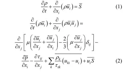
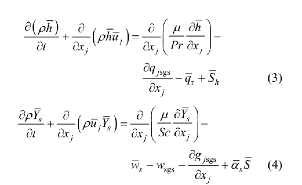
The filtered gas continuity, momentum, energy and species equations for LES of spray combustion can be obtained as [6, 8]
3 SUB-GRID SCALE STRESS MODELS AND GAS COMBUSTION MODEL
A sub-grid scale energy equation (SGS-k-equation) stress model is adopted as
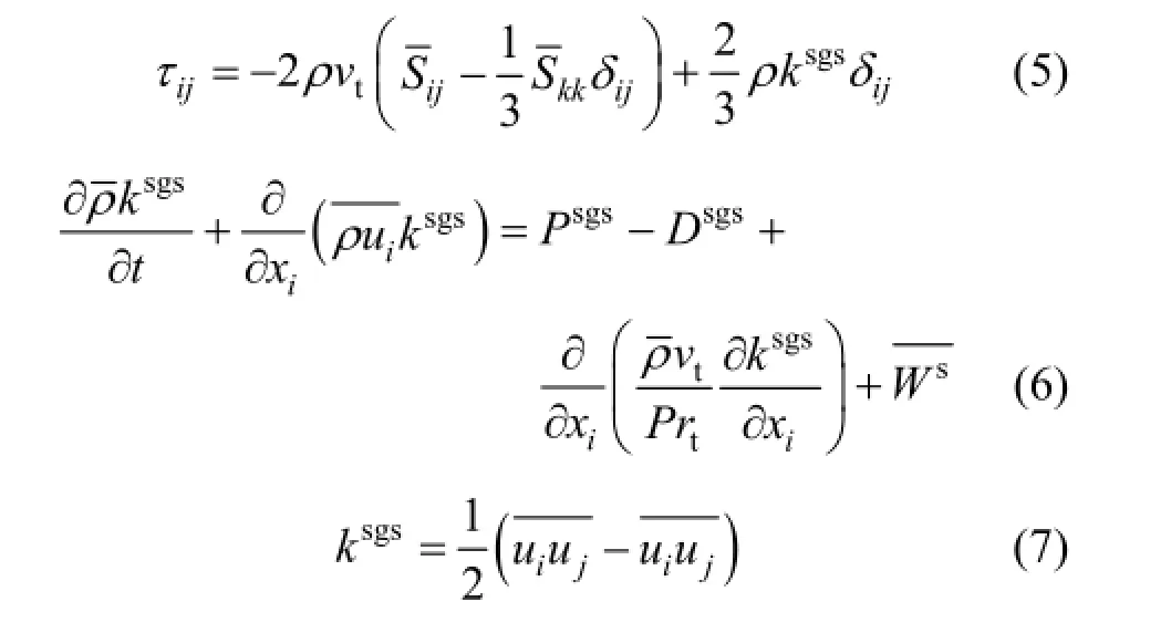

The sub-grid scale heat flux and mass flux are closed using a gradient modeling as

For gas combustion, a finite-rate model is used, that is, the SGS reaction rate is neglected as wsgs=0, and a global one-step reaction mechanism is used for the ethanol-oxygen reaction:

The Arrhenius expression for wsis

The P1 model is used for the radiative heat transfer as

where σ is the Stefan-Boltzmann constant, a isthe absorptioncoefficient a=0.1and G is the incident flux which is solved from the radiative transfer equation. When a→0,→0.
4 DISPERSED PHASE EQUATIONS
The Lagrangian dispersed phase approach is used. It includes the following ordinary differential equations:
Droplet momentum equation:

with
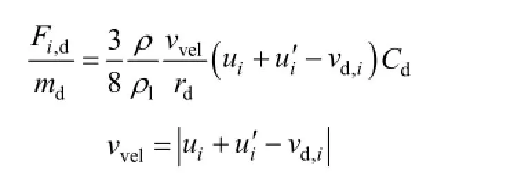
Because the shape of droplets will change in the gas flow field, a TAB (Taylor-Analogy-Breakup) model introduced in the frame of CFD analysis by O’Rourke and Amsden [11] is adopted in this work. So we have

where Cd,sphereis the drag coefficient of a spherical droplet and ydis relative deformation computed by TAB model.
Droplet energy equation:

Droplet evaporation equation:

which is numerically calculated by


The droplet heat and mass transfer during evaporation is based on the Ranz-Marshell law under the effect of Stefan flux [13].
5 MODELING OF SPRAY COMBUSTION
The LES was made for a spray combustor measured at the university of California, Berkeley, as shown in Fig. 1 [14]. The flow parameters are: atomization pressure 2.0 MPa, ethanol flow-rate 0.47 g·s−1for a fixed spray angle of 45° and hollow cone angle 30°, co-flow of air inlet velocity 0.32 m·s−1, temperature 300 K and area of spray nozzle 7.85×10⁻⁵m2. Initial radius of ethanol droplet is 50 μm. The 3-D computation domain is cylindrical with a diameter of 160 mm and a length of 200 mm for main combustion domain. The maximal mesh size is taken as 1.3 mm. The grid cell number is 600000. The time step is 1×10⁻⁶s.
For the numerical procedure, the SIMPLE algorithm with a second-order implicit scheme for the temporal term and a second-order upwind scheme for convection and diffusion terms is used. For boundary conditions, uniform gas inlet velocity, droplet inlet velocity with a spray angle and concentration are given according to experiments. No-slip condition for the gas phase is given at the boundary, and fullydeveloped flow condition is given at the exit. Random fluctuations are superposed to the inlet velocity. The computer code KIVA-LES was developed by the present authors based on the original KIVA-RANS code. Running a case on the PC of intel®core(TM) 2 CPU 2.66 GHz, RAM 2.0 dell takes about 120 h.
6 STATISTICAL RESULTS AND THEIR EXPERIMENTAL VALIDATION
Figure 2 gives the LES statistically averaged gas temperature distribution and its comparison with the RANS modeling results using the PDF equation model reported in [15] and the measurement results at different cross sections. It is seen that the LES results are in much better agreement with the experiments than those obtained by RANS modeling using the most complex PDF equation model. Better agreement is obtained at the cross sections of z=0.006 m and z=0.01 m, as shown in Fig. 2 (a) and 2 (b) respectively. However, there are some discrepancy betweenpredictions and experiments at the section of z=0.02 m, as shown in Fig. 2 (c). The maximum difference is about 300 K at χ=0.016 m. This discrepancy may be caused by neglecting the SGS reaction rate and the simplified global kinetics. Fig. 3 shows the statistically averaged droplet temperature and its comparison with the measurement results. In general, the agreement is good, with only some minor difference, possibly owing to inaccurately specified spray inlet conditions due to the uncertainty given in experimental conditions.
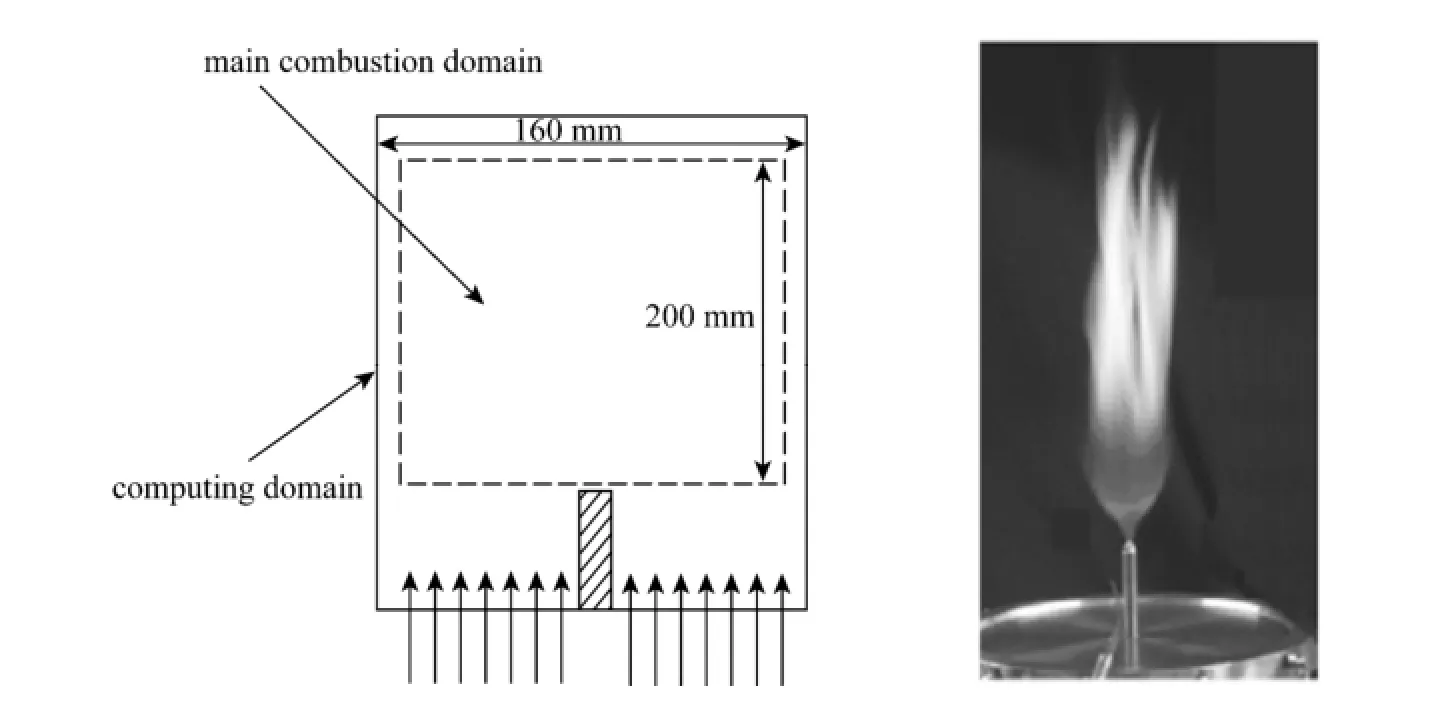
Figure 1 The spray combustor

Figure 2 Statistically averaged gas temperature at different cross sections
The predicted droplet statistically averaged axial velocity, radial velocity and their comparison with the measurement results are given in Figs. 4 and 5 respectively. Predictions and measurements are near to each other, but the droplet axial velocity, in particular at the cross section of z=7.5 mm, is somewhat over-predicted. Moreover, the droplet radial velocity is underpredicted. It can be caused also by the inaccurately given inlet conditions.
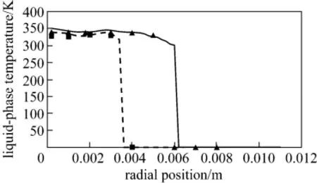
Figure 3 Statistically averaged droplet temperature▲ LES-SOM, z=10 mm; ■ LES-SOM, z=6 mm;Exp., z=10 mm;Exp., z=6 mm

Figure 4 Droplet axial velocity=5 mm, Exp.;=7.5 mm, Exp.; ■ z=5 mm, LES-SOM; ▲ z=7.5 mm, LES-SOM
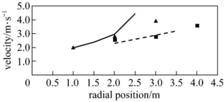
Figure 5 Droplet radial velocity=5 mm, Exp.;=7.5mm, Exp.; ▲ z=5 mm, LES-SOM; ■ z=7.5 mm, LES-SOM
In general, the LES statistical results are well validated by experiments, indicating that for the presently simulated case, the SGS-k-equation model and the finite-rate combustion model are fairly good, and the effect of SGS reaction rate has only minor effect on the statistical results.
7 INSTANTANEOUS RESULTS AND DISCUSSION
Figure 6 shows the predicted instantaneous gas velocity vectors. Fig. 7 gives the predicted instantaneous vorticity maps. The coherent structures initially are produced in the near-inlet shear region of fuel jet flows from Fig. 6 and Fig. 7, then are intensified to become large vortices and finally are weakened in the downstream region. The instantaneous ethanol vapor concentration is given in Fig. 8. Obviously, intensive evaporation takes place in the shear region, but the highest fuel concentration is located not inside the large-vortex region, but is behind it.
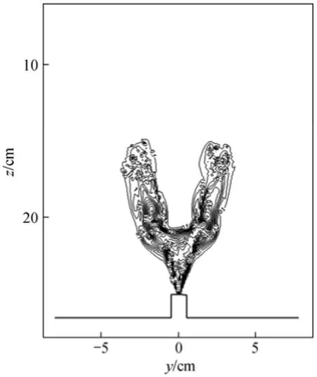
Figure 6 Instantaneous gas velocity vectors
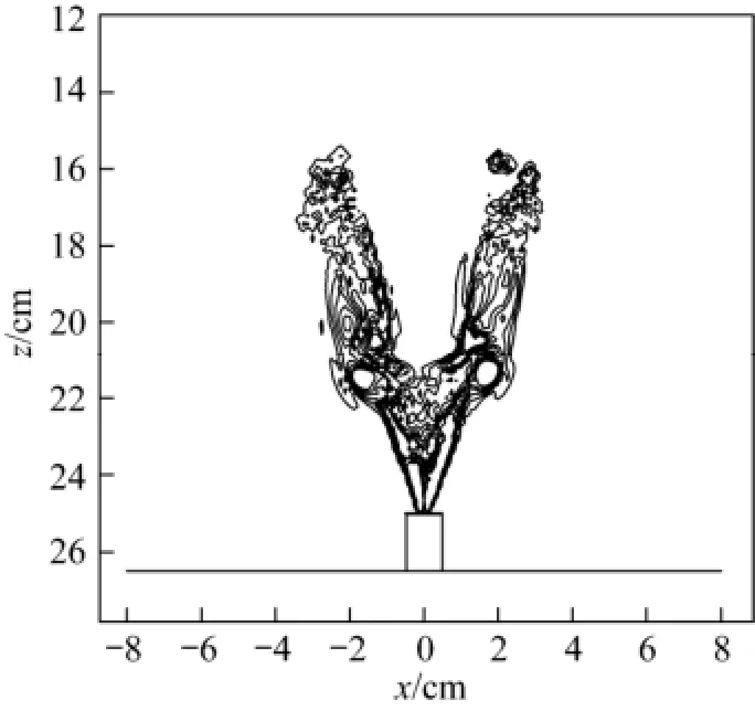
Figure 7 Instantaneous vorticity map in the z-r plane (s−1)
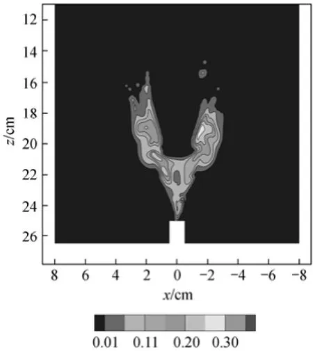
Figure 8 Fuel vapor concentration
Figure 9 shows the droplet size changes during combustion. It is shown that droplet sizes are in the range of 20-100 μm, decreasing due to evaporation. Figs. 10 and 11 give the instantaneous gas temperature maps in the z-r plane and the r-θ plane respectively. Clearly, high temperature develops around the coherent structures in the region of high vapor concentration, but not inside the large vortices. There are many small flame-zone structures, showing the combustion of separate droplet groups. Figs. 12 and 13 give instantaneous CO2concentration and H2O concentration respectively. The CO2and H2O concentrations are higher in the high temperature region. This is certainly a result of fuel-vapor combustion. Fig. 14 shows the instantaneous O2concentration. Unlike instantaneous CO2and H2O concentrations, for O2concentration there are no small-eddy structures in the center of the flame zone. However, a few number of small-eddy structures appear at the top of flame zone.
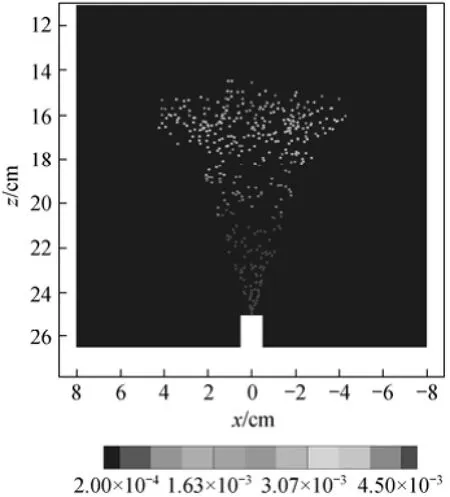
Figure 9 Instantaneous droplet size

Figure 10 Instantaneous gas temperature
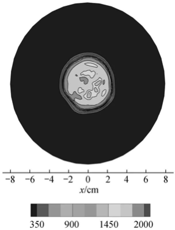
Figure 11 Instantaneous gas temperature at z=0.03 m
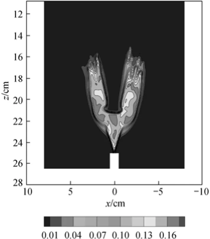
Figure 12 Instantaneous CO2concentration

Figure 13 Instantaneous H2O concentration
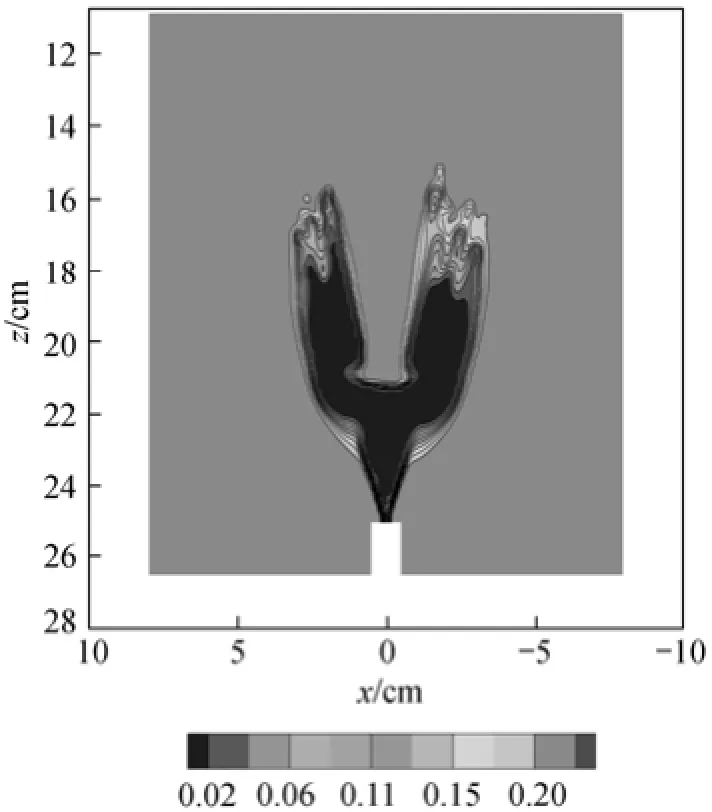
Figure 14 Instantaneous O2concentration
8 CONCLUSIONS
LES of ethanol-air two-phase combustion gives the instantaneous flow and flame structures, showing the interaction among turbulence, droplets and the flame. The prediction of this model is in good agreement with available experimental data and gives many significant qualitative results over a wide range of operating conditions. For the presently simulated case, the LES with a SGS-k-equation model and a finiterate combustion model gives good statistical results for modeling spray combustion, better than those obtained by RANS modeling using a complex PDF combustion model. It is necessary to add the SGS reaction rate to LES of two-phase combustion in the future.
NOMENCLATURE
k sub-grid scale energy, m2·s−2
L evaporation latent heat, J·kg−1
M molecular mass
m mass, kg
P production term
p pressure, Pa
R universal gas constant, 8.314 J·mol−1·K−1
r radius, m
S source term
T temperature, K
V velocity of droplet, m·s−1
wsreaction rate, kg·s-−1
wsgssub-grid reaction rate, kg·s−1
χ χ coordinates
Y mass fraction
ydrelative drop deformation
α concentration fraction
β stoichiometric ratio
µ viscosity, kg·m−1·s−1
τ relax time, s
ρ density, kg·m−3
Subscripts
d droplet
evp evaporation time
fu fuel
g gas
i, j, k components coordinates
l liquid
ox oxygen
sgs sub-grid scale
sh Sherwood number
s s species
t turbulence
vel relative velocity
REFERENCES
1 Zhou, L.X., Wang, F., Hu, L.Y., “Recent advances in fine-scale simulation of spray combustion”, J. Eng. Thermophys., 30 (5), 876-878 (2009). (in Chinese)
2 Zhou, L.X., Li, K., Wang, F., Song, J.O., “Recent advances in large-eddy simulation of spray combustion”, J. Chem. Eng. Ind., 61 (11), 2769-2775. (in Chinese)
3 Li, Y.H., Kong, S.C., “Diesel combustion modeling using LES turbulence model with detailed chemistry”, Combust. Theor. Model., 12 (2), 205-219 (2008).
4 Banerjee, S., Bharadwaj, N., Rutland, C.J., “Investigation of in-cylinder mixing using large eddy simulation models for LTC diesel applications”, In: Spring Technical Conference of the ASME Internal Combustion Engine Division, Milwaukee (2009).
5 Inagaki, M., Nagaoka, M., Horinouchi, N., Suga, K., “LES analysis of engine steady intake flows using a mixed-time-scale SGS model”, In: 5th Joint ASME/JSME Fluids Engineering Summer Conference, San Diego, 1273-1282 (2007).
6 Moin, P., Apte, S. V., “Large-eddy simulation of realistic gas turbine combustors”, AIAA J., 44 (4), 698-708 (2006)
7 James, S., Zhu, J., Anand, M.S., “Large-eddy simulations as a design tool for gas turbine combustion systems”, AIAA J., 44 (4), 674-686 (2006).
8 Patel, N., Menon, S., “Simulation of spray-turbulence-flame interactions in a lean direct injection combustor”, Combust. Flame, 153, 228-257 (2008).
9 Boileau, M., Pascaud, S., Riber, E., Cuenot., B., Gicquel, L.Y.M., Poinsot, T.J., Cazalens, M., “Investigation of two-fluid methods for large eddy simulation of spray combustion in gas turbines”, Flow Turbul. Combust., 80, 291-321 (2008).
10 Yan, Y.W., Zhao, J.X., Zhang, J.Z., Liu, Y., “Large-eddy simulation of two-phase spray combustion for gas turbine combustors”, Appl. Therm. Eng., 28, 1365-1374 (2008).
11 O’Rourke, P.J., Amsden, A.A., “The TAB method for numerical calculation of spray droplet breakup”, SAE Technical Paper 8720 (1987).
12 Amsden, A.A., “KIVA-3V, release 2, improvements to KIVA-3V”, Los Alamos National Laboratory Report, LA-13608-MS, New Mexico (1999).
13 Zhou, L.X., Theory and Numerical Modeling of Turbulent Gas-Particle Flows and Combustion, CRC Press, Florida (1993).
14 Ge, H.W., Düwel, I., Kronemayer, H., Dibble, R.W., Gutheil, E., Schulz, C., Wolfrum, J., “Experimental and numerical characterization of a turbulent spray flame”, Proc. Combust. Inst., 31, 2247-2255 (2007).
15 Ge, H.W., Düwel, I., Kronemayer, H., Dibble, R.W., Gutheil, E., Schulz, C., Wolfrum, J., “Laser-based experimental and Monte Carlo PDF numerical investigation of an ethanol/air spray flame”, Combust. Sci. Technol., 180 (8), 1529 -1547 (2008).
Received 2011-05-11, accepted 2012-05-16.
* Supported by the National Natural Science Foundation of China (5073600, 51266008) and the Research Grant Council of Hong Kong (5105/08E, B-Q10H).
** To whom correspondence should be addressed. E-mail: zhoulx@tsinghua.edu.cn
猜你喜欢
杂志排行
Chinese Journal of Chemical Engineering的其它文章
- Kinetics of Glucose Ethanolysis Catalyzed by Extremely Low Sulfuric Acid in Ethanol Medium*
- Synthesis of Sub-micrometer Lithium Iron Phosphate Particles for Lithium Ion Battery by Using Supercritical Hydrothermal Method
- Hydrogenation of Silicon Tetrachloride in Microwave Plasma
- Effects of Solvent and Impurities on Crystal Morphology of Zinc Lactate Trihydrate*
- Kinetic and Thermodynamic Studies of Acid Scarlet 3R Adsorption onto Low-cost Adsorbent Developed from Sludge and Straw*
- Performance of EDAB-HCl Acid Blended System as Fracturing Fluids in Oil Fields*
