Match design of pure electrical modification and performance analysis for subcompact*
2014-03-18KejunJIANGShaoyiBEIJingboZHAO
Ke-jun JIANG,Shao-yi BEI,Jing-bo ZHAO
School of Automobile and Traffic Engineering,Jiangsu University of Technology,Changzhou 213001,China
1.Introduction
Today the increasingly serious environmental problem becomes an important obstacle for the development of society.As an ideal and green transportation,the electric vehicle(EV)has the advantages of energy saving and low pollution,which is an important approach to alleviate the pressure of the urban environment in the future[1].The survey of McKinsey Company in Shanghai in 2010 showed that the average daily travel distance of 76% people is less than 75 km[2].And this kind of travel requirement provides the great momentum and a wide market space for the miniaturization of electric car.
This paper will study the method and process of electric driving system modification for subcompact.Based on the Alto subcompact,and according to the demands of dynamic performance and economy,the main components of pure electric driving system will be match-designed.Then by using the advisor software and real vehicle tests,the performance of this design will be analyzed,and the feasibility of the design will be verified.
2.Design scheme and performance requirements
Alto subcompact chassis has the FWD design in structure,of which the engine is in the front,and the front wheels are the driving wheels.For the economic considerations,the design scheme of driving system modification was showed in Figure 1.In this scheme the drive motor is installed on the final drive,and drives the two driving wheels through the final drive and the differential.
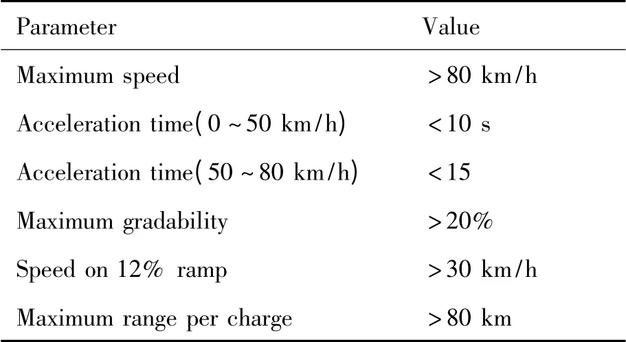
According to reference[3],it is well known that the main usage of mini electric vehicle is to meet the requirement of short-distance traffic within city.Based on the relevant provisions of GB/T28382-2012 Technical Specifica-tions of Pure Electric Passenger Car,the design and performance requirements as shown in Table 1 were put toward.

Figure 1.Design scheme of driving system modification

Table 1.The performance requirements of design
3.Calculation and match design of parameters
In the modification and match design,the first question is to meet the performance requirement,such as driving range,maximum speed,and acceleration time and etc.Therefore,this paper started to match design from three aspects:driving motor,transmission and battery capacity.
3.1.Calculation of driving motor parameters
Driving motor parameters include power,torque and speed range.The power of driving motor is the key,and it can be decided by the power requirement of the vehicle when driving.According to The Theory of Automobile[4],the vehicle longitudinal dynamics could be expressed as follows:


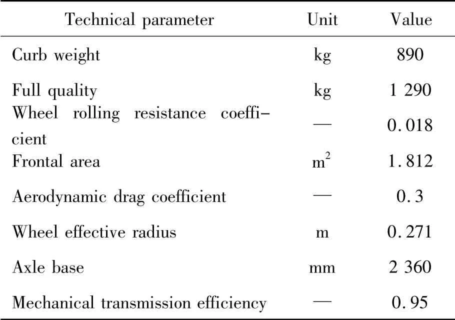
Where,Fd,Fw,Fi,Ffand Fjare wheel driving force,air resistance,slope resistance,rolling resistance and accelerating resistance,respectively,Cd,A and V are aerodynamic drag coefficient,frontal area and vehicle speed,respectively,M,g,f,α and δ are vehicle mass,gravity constant,wheel rolling resistance coefficient,road ramp angle and conversion coefficient of rotary mass,respectively.According to Ref.5,δ is set to 1.1 in this paper,Td,R,i0and igare the output torque of driving motor,wheel effective radius,final drive ratio and gear ratio,respectively.ηtis the mechanical transmission efficiency,which is set to 0.95 in the paper.
In order to calculate the required power,this paper references the main technical parameters(as shown in Table 2)of Suzuki Alto subcompact(2013),and calculated the power of driving motor for maximum speed,climbing performance and acceleration time.

Table 2.The main parameters of Alto subcompact(2013)
When the car is running steadily at top speed on the flat road,power demand is mainly to overcome air resistance and rolling resistance,at this situation,the motor power demand could be expressed as:

Put the related data in Table 1 into the formula(7),we can get the value of P1is 9.2 kW at speed of 80 km/h(22.3 m/s).
When the car is running at a certain speed on the ramp,the motor power demand could be expressed as:

Put the related data in Table 1 into the formula(8),we can calculate the P2.When the car is running at speed of 10 km/h(2.8 m/s)on the road with 20% slope,the value of P2is 8.0 kW.If the speed increased up to 30 km/h(8.3 m/s),and the slope of the road decreases to 12%,the value of P2will be 15.5 kW.
When the electric vehicle accelerates on the horizontal road,the speed and the power demand of electric vehicle are highly nonlinear,and we can’t determine the transmission ratio at first,so in this paper we used the law of conservation of energy to obtain the driving motor’s power.
According to the performance requirements(see Table 1),the vehicle speed should be increased to 50 km/h from zero in 10 seconds.When the speed reached up to 50 km/h,the kinetic energy of vehicle is:

The increase rate of kinetic energy is:

Furthermore,we should consider the air resistance and rolling resistance during acceleration process.Using formula 2 and 3,we figured out the air resistance and rolling resistance at 0.89 kW and 3.16 kW.Plug all these data together,the demand for driving power during acceleration process could be calculated as follows:

The peak power of the driving motor should meet the requirements of formula(9).

According to the formula(9),the peak power of the driving motor should be greater than 17.4 kW.On this basis,increase the power by 25% for the backup power,and finally we determined the drive motor power of 22 kW.
In consideration of cost,efficiency and control fa ctors,the permanent magnet brushless motor was chose.This kind of motor has advantages of large power density,high efficiency and good performance of cost-effective[5 -7].
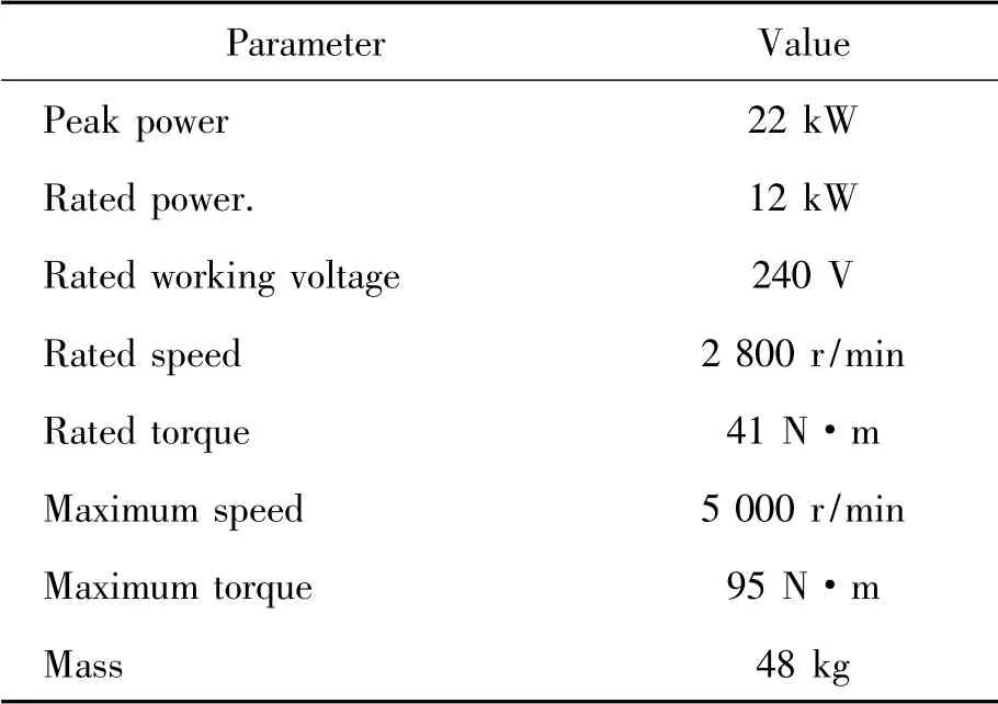
Since the discharge current will affect the output power and discharge efficiency of the battery directly,we should control the working current of driving motor,which is equal to the discharge current of battery to a great extent.From this point,the higher working voltage of driving motor is better,and the higher working voltage can ensure the working current in a certain range in circumstances where both the safety and the drive motor power could be meeted.Accordingly we set the rated working voltage of the driven motor at 240 V,the details of the driving motor parameters were shown in Table 3.

Table 3.Detailed technical datum of PM brushless motor
3.2.Calculation of transmission ratio
For pure electric vehicle,the calculation of transmission ratio mainly includes the calculation of final drive ratio,gear number determination and calculation of gear ratio of driveline.
Firstly,the total transmission ratio will be determined.At this point,the maximum speed and the maximum driving torque requirement should be considered.According to the theory of automobile[4],the maximum speed and the maximum driving torque requirement of electric vehicle could be obtained as follows:

Where,∑i is the total transmission ratio,and Tmaxis the maximum torque of driving motor.Substitute nmax=5 000 r/m(83.4 r/s),R=0.271 m and Vmax=80 km/h(22.3 m/s)into formula(10),we can get:

Based on the requirements about maximum driving torque in formula(11),we can get the lower limit of the total transmission ratio.The maximum driving torque will be needed when driving on the road with maximum slope,and it could be evaluated by the following equation.

Combining formula(13)and formula(14),we could understand that single transmission ratio can not meet the requirements of designing,hence the two-gear transmission was chosen.We set the total transmission ratio of the two gears of 8 and 5.In order to save the cost,we will use the original components of Alto’s transmission system as could as possible.From the service and maintenance manual of the sedan,we found the final drive ratio is 4.35.According to formula(12),the gear ratios were set to 1.84 and 1.15.
3.3.Match design of battery parameter
The battery is the only energy source for the pure electric vehicles,so the battery parameter design is the key of pure electric vehicle design.Match design of battery parameter has to be considered from two aspects:the power consumption and electricity consumption when electric vehicle driving.
1)The choice of battery output voltage
Battery output voltage should be matched with the working voltage of driving motor.So battery output voltage was set to 240 V,which was equal to the working voltage of driving motor.
2)Determination of the battery capacity
Battery capacity could be determined by driving range and maximum power mainly[8].According to the design requirements listed in Table 1,driving range per charge must be greater than 80 km.In an earlier paragraph,we get the result that the power requirement was 9.2 kW when the car was driving steadily at 80 km/h on the straight and flat road.Therefore,we can deduce that Running 80 km need charge is 9.2 kW·h.
Assuming the depth value of discharge(DOD)is 0.7,and then the battery capacity could be calculated as follows.

Of course,we still should consult the specification of the battery on market.At last,the battery with 50 Ah capacities was chosen.
3)The choice of battery type
Now common batteries are lead-acid battery,lithium-iron battery,nickel-metal hydride battery and nickel-cadmium batteries.After comprehensive comparisons,the lead-acid battery has been chosen in this paper as power source of the pure electric vehicle.As we know,the output voltage of single leadacid battery is 12 V,in order to achieve the output voltage of 240 V,we should put 20 batteries in series,and the total mass of them is about 260 kilograms.
4.Vehicle performance simulation and optimization after modification
4.1.Performance simulation
To analyze the dynamic performance of modified vehicles,this paper used the ADVISOR software to conduct the vehicle performance simulation.ADVISOR can only be run in Matlab/Simulink environment,and it is a reverse type software for vehicle performance simulation.Its electric vehicle simulation flow is shown in Figure 2.

Figure 2.Reverse simulation flow diagram
Consult the above design results,set up each models and their parameters as shown in Figure 2,the CYC_UDDS driving cycle shown in Figure 3 was adopted.Then we got the simulation results(see Table 4)after running this model.Based on the results,we can see that the match design is successful,and have accomplished the design requirements.
4.2.Transmission ratio optimization
On pure electric vehicle,when the driving motor and battery system are determined,the transmission ratio is the parameter which could affect the power and economy performance ultimately.

Figure 3.Driving cycle graph

Table 4.Simulation results
In this paper,since the final drive ratio was fixed,we only need to optimize the gear ratio of transmission.Hence the optimization design variables were chose as follows.

Where,ig1,ig2are the transmission ratios of two gears,respectively.
The optimization purpose of transmission system is to comprehensively improve the dynamic performance and power consumption performance of pure electric vehicle.As we know,for pure electric vehicle,acceleration time is the main parameter of dynamic performance,and travel distance is the main parameter of power consumption and economic performance.So we selected the acceleration time and the travel distance as constrained conditions to optimize the gear ratios.
According to formula(1)~(6),objective function of acceleration time could be expressed as:

Where,t0is the shifting time of transmission,according to the shift test of AMT,the shifting time is about 0.3 ~0.9 s,hence we set the shifting time to 0.5 s.vt1is the vehicle speed when it is shifting,it can be calculated according to the shift schedule,in this paper,we used acceleration equal principle to get its value:44 km/h.
Objective function of driving distance could be expressed as:

Where,E is the total power when the battery is charged fully,∑Wiis the power consumption in a drive cycle,S is the driving distance in a drive cycle.The dynamic and economic performances of vehicle are contradictory and restricted mutually.To take care of both,the double objective optimization function was set up based on the dynamic performance(acceleration time)and power consumption(travel distance).

Where,α and β are the weighting factor of dynamic performance and power consumption,both of them are important to the whole performance of electric vehicle.For this reason,we set their value to 0.5 equally.Then by using Fmincon optimization function in Matlab,the minimum value of the objective function was optimized,and the optimization results were shown in Table 5.

Table 5.Optimization results
According to the optimization results,adjusted the value of parameter gb ratio in ADVISOR,and changed vt1to 41 km/h,then ran the simulation with CYC_UDDS driving cycle,we got the simulation results after the optimization,which was shown in Table 6.
Comparing Table 4 and Table 6,we can see acceleration time(0 ~50 km/h),maximum speed and climbing performance were improved marginally after optimization,but driving range per charge and acceleration time(50 ~80 km/h)were down a little.It means that the optimization work is effective and it has achieved the balance of performance.

Table 6.Simulation results after optimization
5.Test and analysis
According to the obtained above results,we modified the Alto subcompact,and carried out the real vehicle tests(see Figure 4).With the help of plate type automobile safety performance tester,we measured the weight after modification was 1135 kg.Then by using the photoelectric auto performance detecting instrument,we measured the dynamic performance datum of pure electric vehicles as shown in Table 7(There were the driver and equipment operator in the sedan,the total weight was 130 kg).Comparing the Table 6 and Table 7,we found the test results of the real vehicle had exceeded the design requirements,That was to say the initial goal of design had been achieved.

Figure 4.Photos of main components and test image

Table 7.Real vehicle dynamic performance test results
But we still found the measured performance of real vehicle was worse than the results of simulation based on the whole performance.The main reasons were analyzed as follows.
1)During first design process,we assumed the road was flat and straight,but in fact the road was not straight and always with a slight slope,which led to a decline in performance[9].
2)During tests,the vehicle speed was controlled by feedback control method,and this process had the delay and the volatility,which was different to the simulation in the software,so this also led to the differences in performance.
3)The wind existed in the actual test environment,which made the actual air resistance did not conform to that of the theoretical calculation,and this also affected the accuracy of calculation process in design.
4)Environmental factors(mainly the temperature)influenced the output of the battery,but the extent of influence was expressed inaccurately in the simulating model.
5)The model of vehicle accessories needs to be refined.In this paper,the power of accessories was ignored,and the parameters such as acc_mech_pwr and cc_elec_pwr were set to zero.This approach simplified the design process,but ignored the energy consumption of panel,lights,brake lights,and other accessories,which could decrease the performance of vehicle in actual test.
6.Conclusion
In this paper,match design of a pure electric vehicle was done based on modification of the Alto mini sedan,the main parameters of driving motor,battery,transmission and so on were calculated.In order to predict the performance of the modified vehicle,the simulation of the modified vehicle in ADVISOR software was performed.On the basis of the simulation results,the optimization of the transmission ratios was done to balance the performance of dynamic performance and power consumption economy.All results of simulation show that this method and process of match design are correct and feasible.The test results of real modified vehicle also show the matching design has reached the design target.However,the difference between the simulation results
and test results exist as well,the main reasons of this phenomenon is the environmental factors which had not been considered thoroughly during the calculation and simulation process,but most of them can affect the vehicle performance.The persons who will dedicate themselves to pure electric vehicle design and research should be able to obtain some reference from this paper.
[1]YANG Yusheng,CHEN Qingquan,CHEN Liquan,et al.The proposal of technology development route about Chinese electric vehicle[J].Advanced materials industry,2010(3):11-17.
[2]Woetzel J,Sha Sha,Zhang Haimeng.Electric Vehicles in Megaci-ties-Shanghai Charges Up[R].Shanghai: McKinsey & Company,2010.
[3]http: //www.ceva.org.cn/cn/viewnews/20130111/20 13111103546.htm.
[4]YU Zhisheng.The theory of automobile(the fifth edition)[M].Beijing: China Machine Press,2009:2-31.
[5]GAO Yanling.Automobile application engineering(the third edition)[M].Beijing: China Communication Press,2004:2-31.
[6]GUO Zekang.A study on the optimization for the dynamic performance of pure electric vehicle[D].Hefei:Hefei University of Technology,2012:13-14.
[7]http: //www.cxfuwu.com/html/c64/2008 -10/96 00.html.
[8]JI Fenzhu,GAO Feng,Zhou Rong Parameter design for driving line of power train and study on driving range of EVS[J].Journal of Liaoning Technical University,2006,25(3):78-82.
[9]CHEN Chan.Research on shift Schedule and Evaluation method of automotive automated manual transmission[D].Chengdu: Xihua University,2006:30-34.
杂志排行
机床与液压的其它文章
- Analysis of magnetic field characteristics for different winding cylinder materials of a new type of magnetorheological damper*
- Influence of salt fog test on the performance of the composite coating on avionics cases
- Emergency information integration for a kind of heterogeneous production system with uncertainty*
- Flow field CFD analysis of axial flow blood pump*
- Cam profile optimization design of variable cycle reciprocating piston engine*
- Control system design of automatic down-filling machine based on ARM7TDMI*
