Cam profile optimization design of variable cycle reciprocating piston engine*
2014-03-09LimingDIWanliSUNYingSHIWenfengWANG
Li-ming DI,Wan-li SUN,Ying SHI,Wen-feng WANG,,,;
2Shenyang Jiashi Judicial Identification,Shenyang 110023,China;
3Research Institute of Highway Ministry of Transport,Beijing 100088,China
Cam profile optimization design of variable cycle reciprocating piston engine*
Li-ming DI†1,Wan-li SUN2,Ying SHI3,Wen-feng WANG11School of Vehicle and Energy Sources,Yanshan University,Qinhuangdao 066004,China;
2Shenyang Jiashi Judicial Identification,Shenyang 110023,China;
3Research Institute of Highway Ministry of Transport,Beijing 100088,China
The kinematics and dynamics simulation model for valve gear of HONDA 125 mL single-cylinder four-stroke gasoline engine was studied with the software of Excite_TD,by analysing and comparing the performance indexes of the cam profile design methods between polydynamic cam(POL)and individual section acceleration cam(ISAC).ISAC was chosen to optimize the intake and exhaust cam profile for the variable cycle reciprocating piston engine(VCRPE)in fourstroke or two-stroke mode.In order to validate the rationality of the cam profile design,the multibody dynamics simulation model of the corresponding valve gear was established and analyzed by SolidWorks.Through comparison of the dynamics simulation results between Excite_TD and SolidWorks,it shows that the results from Excite_TD are consistent with that from SolidWorks,which verifies the accuracy of cam profile optimization as well.
Reciprocating piston engine, Variable cycle, Valve gear, Cam profile,Optimization design
*Project supported by Hebei Education Department in China Natural and Science Research of Hebei Education Department in China(No.2009160),Doctor Key Foundation of Yanshan University(2013925)and Corporation Unit Exploitation Project of Yanshan University(2013101)
†Li-ming DI,Associate professor.E-mail:diliming@ysu.edu.cn
1.Introduction
Variable cycle reciprocating piston engine (VCRPE)combines the two-stroke and four-stroke mode together.For improving engine load factor,VCRPE can switch between the two-stroke and fourstroke mode timely according to engine operating condition,which provides a new method for engine miniaturization and lightweight design[1-4].Valve train directly affects the engine performance,and good valve gear can ensure engine’s smooth operation, less vibration and noise,and good life cycle.Cam is an important part of the valve gear,and its profile has a direct impact on valve motion and valve timing.Reasonable organization with the valve timing will ensure the gas exchange thoroughly and reduce the exchange losses.
VCRPE was realized by transformation of fourstroke engine with existing air supply system,fuel system,cooling system,lubrication system and exhaust purification system[3-4].In the VCRPE working process,four-stroke mode and two-stroke mode can be realized by controlling the intake and exhaust valve opening and closing time.Thus,reasonable design of the cam profile has an important influence on the performance of the VCRPE.
Cam design includes ramp section and working section.Ramp section has three design methods,which are rectangle function,cosine function and trapezoid function,and includes three parameters that are ramp height at the valve,total length of ramp and velocity at section end.Rationalization with the design methods and parameters ensure the smooth connection between ramp and working section,and avoid the speed,acceleration and the contact force exceeding the allowable limits.Working section also has three design methods,which are constant acceleration cam(STAC),polydynamic cam(POL)and individual section acceleration cam(ISAC),and each method has its application field.STAC is used for large and medium-sized low-speed engines,and POL is mostly applied for the tappet valve gear.STAC,which can freely mix arbitrary function and deposit flexibly,is applied to any kind of valve gear,and it’s the preferred method in cam optimization[5-10].
The research object is HONDA 125 mL singlecylinder four-stroke gasoline engine in this paper.According to the design requirements of VCRPE valve gear,the professional software Excite_TD of AVL Company was used to establish the kinematics and dynamics simulation model.Then POL and STAC method were adopted to design the cam profile.By analyzing and comparing the performance index of the cam profile,the best design method was finally chosen to optimize the intake and exhaust cam profile for VCRPE in four-stroke or two-stroke mode.In the case of lacking in experimental conditions,the multibody dynamics simulation model of the corresponding valve gear was established and analyzed by Solid-Works,results from Solidworks multi-body dynamics simulation were used to verify the accuracy of the Excite_TD dynamics simulation.
2.Intake cam profile design offourstroke mode
The various parameters required for POL design method were reasonable selected by the orthogonal test in reference[11],adopted POL symmetric method and designed the intake and exhaust cam profile of four-stroke mode of VCRPE,the results basically meet the design requirements.However,the negative radius of curvature appears in the kinematics evaluation,which increases the difficulty of cam manufacture.If the minimum radius of curvature is smaller than the radius of cam follower,the follower couldn’t contact with the cam profile.On the basis of kinematics and dynamic simulation model in reference[11],the cam profiles were optimized by Excite_TD in this paper.
2.1.Establishment of simulation models
Cam design speed was at 4 000 r/min which is the maximum torque crankshaft speed of four-stroke mode,and the valve timing when valve lift at 1 mm is shown in Table 1.In ramp section design,cosine ramp was selected.Ramp height aims to eliminate the valve clearance and elastic deformation of the valve gear,in this paper it was set at 0.15 mm.Velocity at section end not only affects the shape of ramp,but also influences characteristic of the working section[12],this paper chose 250 mm/deg.
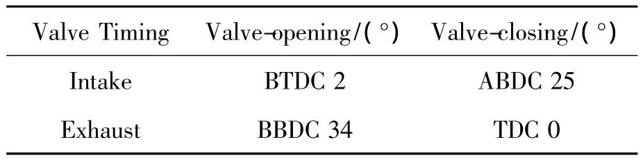
Table 1.Valve timing for valve lift at 1 mm
The Excite_TD kinematics and dynamics simulation models of four-stroke mode valve gear were shown in Figure 1 and Figure 2.
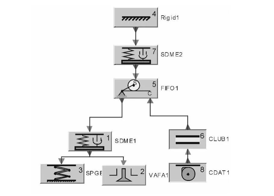
Figure 1.Kinematics simulation model of valve gear
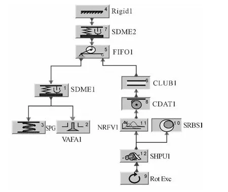
Figure 2.Dynamics simulation model of valve gear
To compare the advantages and disadvantages of different cam design methods,two cam profile design plans are set up.Plan 1 was based on the asymmetric design,the opening section used POL method while the closing section used the STAC method.Plan 2 was also based on the asymmetric design,the opening section used STAC method and the closing section used STAC method too.
2.2.POL and STAC cam profile design
1)POL cam profile design
The mathematical expression for working section of POL cam profile design method[13]is:
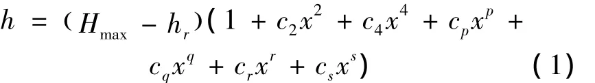
whereHmaxis the cam maximum lift;hris the ramp height;x=1-φ/Φ,and Φ is the half main cam length which is 65 deg in this paper;φ is the cam angle,the starting point of cam angle is defined as φ=0;constantc4is mainly used to control the shape of negative acceleration and its generally recommended value is 0.1,0.2 and 0.4.This paper chose 0.1;constantscp,cq,cr,csare decided by the boundary conditions,positive integer exponentsp,q,r,sare greater than or equal 8 and at the same timep<q<r<s;cam profile curve junction need to meet three conditions:the lift curve in junction is continuous,the velocity curve is consecutive and the velocity is zero,and the acceleration curve is continuous and reaches the negative maximum number.Exponent parameters chosep=12,q=24,r=32,s=46 in this paper.
2)STAC cam profile design
STAC method has three functions to define the cam profile which includes linear function,polynomial and sine function.STAC connects different sections of cam profile by circular arc to improve the stability of the valve gear,and ensure that the fullness ratio of the cam profile meets the design requirements,it’s a kind of flexible and effective cam profile design method[14].In cam profile design process,the design curve type is mainly determined according to the speed,acceleration,jerk,torque and complexity of the curve matched[15-16].
The closing section of plan 1,opening and closing section of plan 2 were all adopted of STAC method,and their parameters are shown in Table 2 and Table 3.
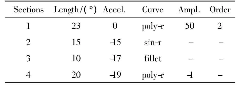
Table 2.Closing section of plan 1
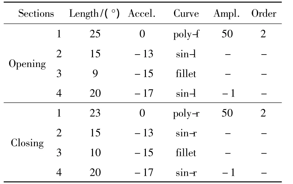
Table 3.Parameters of plan 2
2.3.Kinematics and dynamics simulation analysis
1)Kinematics simulation analysis
Kinematics evaluation rules include valve lift,velocity,acceleration,radius of the curvature,fullness ratio of the valve lift,the maximum jerk and cam contact force.Cam design should ensure that all the parameters meet design requirements,and then carrying preliminary kinematics analysis on the valve gear.
Comparing Figure 3 and Figure 4 in kinematics analysis,the valve lift and valve timing both meet the design requirements in two different plans.Curves of valve lift and speed are smooth and continuous,which indicate that the valve gear operates Smoothly.The peak valve acceleration is in a reasonable range.The acceleration curve is smooth and continuous and there is no large mutation,indicating that the valve gear operates well in this speed.
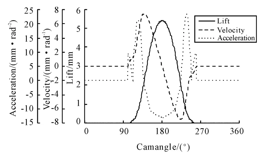
Figure 3.Valve lift,velocity and acceleration of plan 1
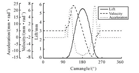
Figure 4.Valve lift,velocity and acceleration of plan 2
Other kinematics parameters are shown in Table 4,and all of the parameters meet the design requirements.In cam design,fullness ratio is used to evaluate the time-area value.Bigger of the fullness ratio,better of the charging efficiency,and generally it approximately takes about 0.55.The maximum jerk is usually used to evaluate the stability of valve gear,and it is generally defined less than or equal to 1 000 mm/rad3.The materials of cam and follower in this valve gear are cold cast iron and steel,the maximum permissible contact force between these two materials is 1 250 N/mm2.Coefficient κ is used to describe the relationship between length of positive acceleration section and the vibration.in general,κ is required to greater than 1.2~1.3[12],if κ does not meet the design requirements,it easily lead to resonance.Length of positive acceleration section directly influences the minimum radius of curvature,however,there is no specification on the length of positive acceleration section.As shown in Figure 5,radius of curvature in plan 1 appears to be negative at the opening section,the reason is that,valve timing at 1 mm valve lift is provided which means cam profile length is fixed,and this problem can not be solved by increasing the cam length.STAC method which used in plan 2 can subjective control the cam profile length of each section and avoid the negative radius of curvature.
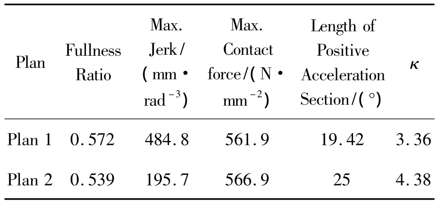
Table 4.The kinematic parameters
2)Dynamics Simulation Analysis
Comparing the dynamic simulation results of the two plans in the engine’s maximum power speed of 7 000 r/min,the maximum valve lift both is 5.4 mm which is consistent with the design value(Figure 6).Considering of the elastic deformation and impact in dynamic model,the velocity curve has slight fluctuations without large mutations(Figure 7).Both of the valve velocity curves are consistent.The valve-seating velocity is less than 0.7 m/s,meeting the design requirements.The fluctuation of acceleration curve at the opening section of plan 1 is bigger than that of plan 2(Figure 8).In the comparison of cam contact force,the contact force of plan 1 has appeared 0 N in 7 000 r/min crankshaft speed,indicating that the valve gear has fly off phenomenon.However,there is no such phenomenon in plan 2.The comparison of contact force between plan 1 and plan 2 is shown in Figure 9.
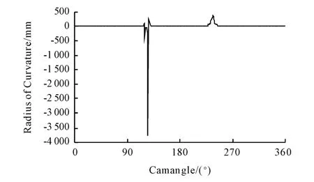
Figure 5.Radius of curvature for plan 1
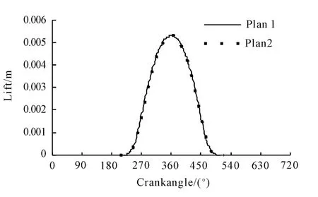
Figure 6.Comparison of valve lift
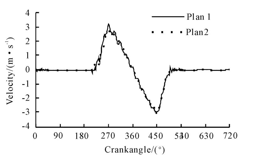
Figure 7.Comparison of valve velocity
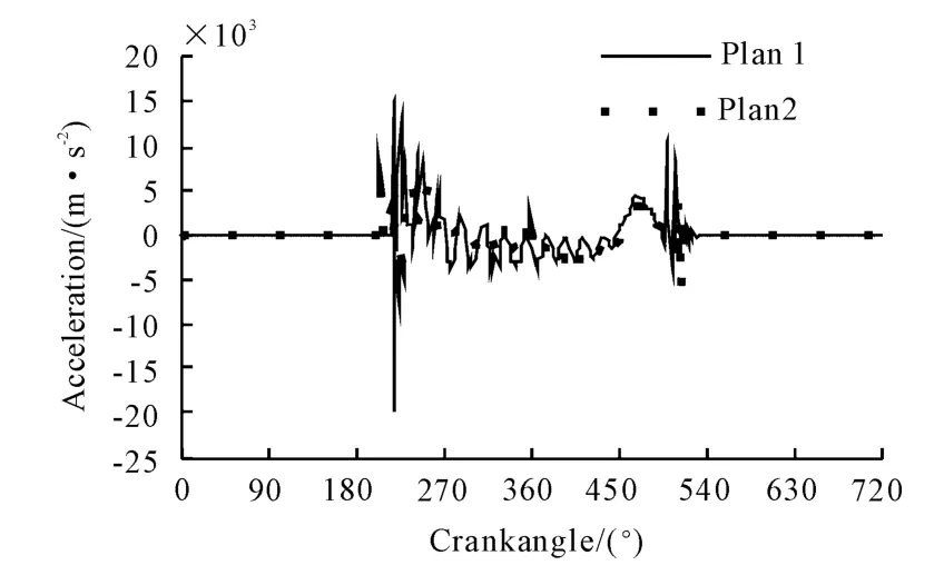
Figure 8.Comparison of valve acceleration
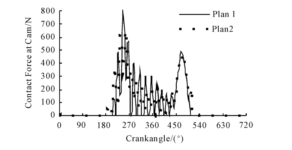
Figure 9.Comparison of the cam contact force
According to the above analysis,STAC design method can effectively solve the negative curvature radius and obviously improves the dynamic performance in high speed.Therefore,STAC method should be adopted in opening and closing section design of cam profile.
2.4.Comparison on dynamics simulation results of Excite_TD and SolidWorks
Limited by the experimental conditions,the dynamic test of valve gear cannot be carried out.For testing the accuracy of dynamic simulation results,SolidWorks was used to establish the multi-body dynamics simulation model.Cam profile needed by SolidWorks was exported from Excite_TD,and dynamicsperformance was calculated in different speed.The dynamics simulation results of Excite_TD and SolidWorks were analyzed separately in the valve lift,valve speed,acceleration and cam contact force.Consistency and tendency of the curve would be compared to evaluate the dynamic performance of the valve gear.
These two kinds of software use different simulation calculation methods,different simulation environment and different processing method with the model related components,so they are independent.Due to lack of experiment condition,using general multi-body dynamics software SolidWorks analysis results to verify the accuracy of the professional software Excite_TD simulation results has certain feasibility.
Take the comparison of analysis results in the maximum torque crankshaft speed of 4 000 r/min as example,the various dynamics performances would be elaborated separately,as shown in Figures 10~13.
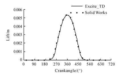
Figure 10.Valve lift in 4 000 r/min
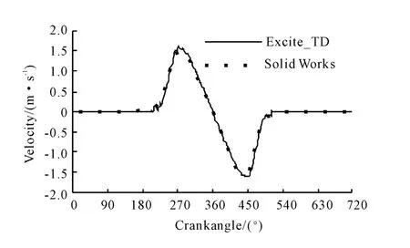
Figure 11.Valve velocity in 4 000 r/min
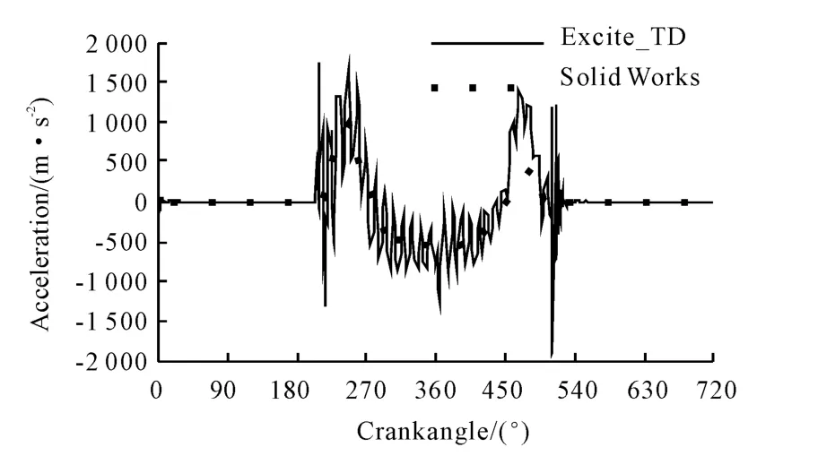
Figure 12.Valve acceleration in 4 000 r/min
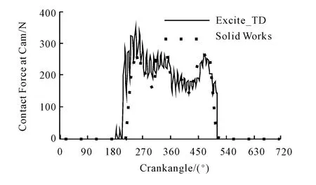
Figure 13.Cam contact force in 4 000 r/min
From above figures we can know that,in 4 000 r/min crankshaft speed,Excite_TD’s valve lift is consistent with SolidWorks’s,and the curves are smooth and continuous without bounce,showing that the valve gear is well operated.So does the velocity curve.In the comparison of acceleration,the fluctuation obtained from Excite_TD is bigger than that from SolidWorks.Because Excite_TD is one-dimensional dynamic simulation software,and SolidWorksis three-dimensional dynamic simulation software,they are different in the algorithm,environment and accuracy of the simulation which lead to the inconformity in simulation results.However,the tendency of the two software simulation results is still consistent with each other.
3.Exhaust cam profile design of fourstroke mode
According to the experience of intake cam design,the exhaust cam of four-stroke mode adopts the same method with the intake cam,meaning that both the opening and closing section use STAC method.The concrete parameters are shown in Table 5.
Unlike the intake cam,cylinder pressure and exhaust back pressure should be taken into account in exhaust cam design.Data of cylinder pressure and exhaust back pressure are obtained by performance simulation with software of BOOST.
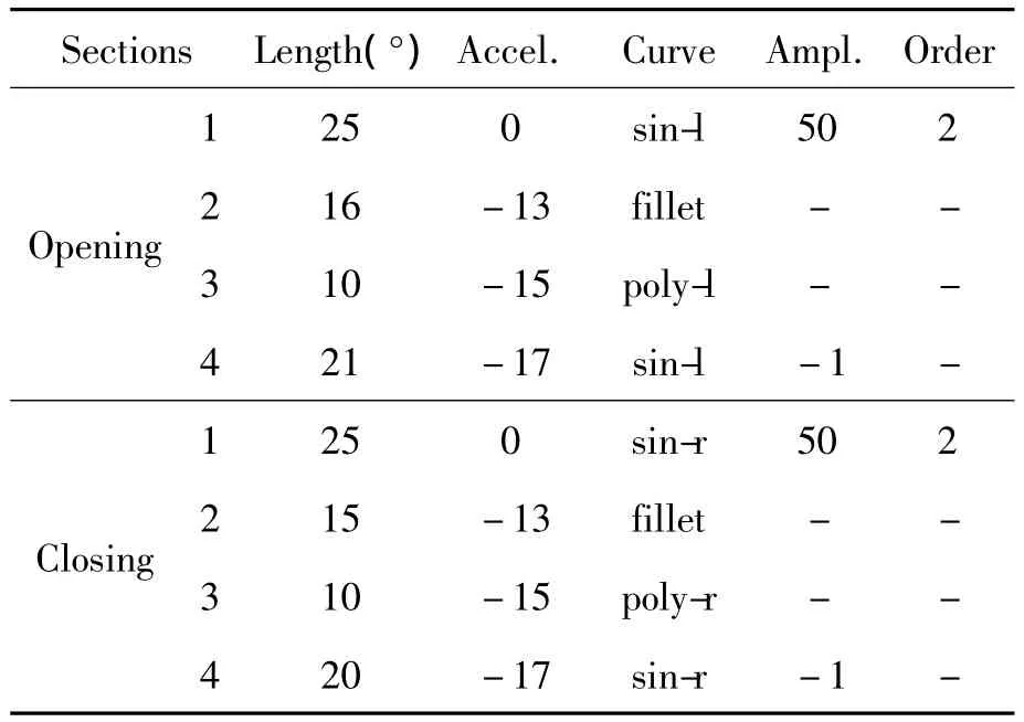
Table 5.Parameters for exhaust CAM
3.1.Kinematics and dynamics evaluation of exhaust cam
The simulation calculation process is consistent with the intake cam,thus there is no need to repeat.The simulation speed still chose the maximum torque crankshaft speed of~4 000 r/min,and import the cam profile,cylinder pressure and exhaust back pressure into the model to simulate the kinematics and dynamics performance.
Kinematics evaluation results are shown in Figure 14 and Table 6.All of the parameters meet the design requirements and the valve gear operates stably in 4 000 r/min.
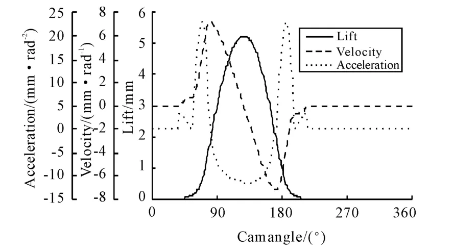
Figure 14.Valve lift,velocity and acceleration for four-stroke exhaust cam
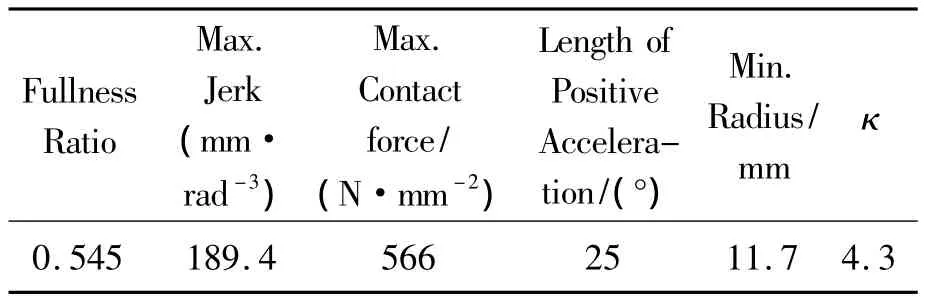
Table 6.The kinematic parameters
Dynamic evaluation results are shown in Table 7,and all of the parameters meet the dynamic design requirements in this speed.
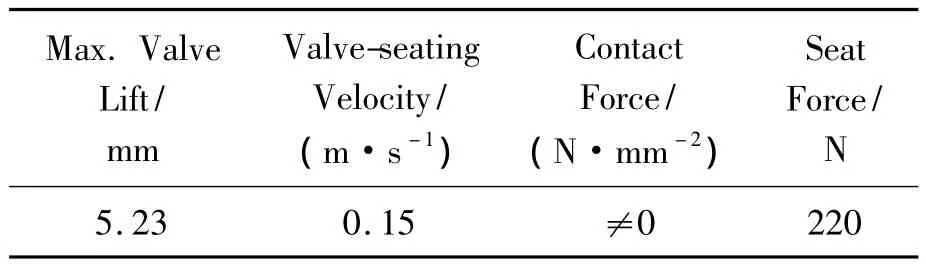
Table 7.The dynamics parameters
3.2.Dynamics validation of exhaust cam
SolidWorks is also used to simulate the multibody dynamics performance in exhaust cam design.The comparison of simulation results between Excite_ TD and SolidWorks show that,the valve lift curve coincides with each other in all speed,the curve is smooth and continuous without significant inverse and the maximum valve lift is 5.23 mm,complied with the design requirements.The valve velocity enhances with the speed increasing gradually,but the simulation results are kept in the reasonable range,the valve seating velocity is less than 0.7 m/s.With the increase of speed,valve acceleration is gradually increasing and the fluctuations at the opening and clos-ing section are still exist in Excite_TD simulation results,which in line with the actual situation.Because of the diversity in material setting and simulation environment,and the contact force is different too.SolidWorks responses slower than Excite_TD in low-speed,but the maximum force is consistent with that of the Excite_TD.As the speed increasing,the response condition of SolidWorks contact force is improved and the tendency is consistent with the tendency of Excite_TD simulation results.The contact force is less than six times of spring preload force and without 0 N contact force situation within the work section.Dynamics validation between Excite_TD and SolidWorks indicates that,the higher speed,the more they consistence with each other.
4.Cam profile design for two-stroke mode
The optimization design for four-stroke intake and exhaust cam indicates that STAC method has better superiority,and it provides a effective approach to the two-stroke cam design.
When crankshaft speed is 4 000 r/min in fourstroke mode,the camshaft speed is 2 000 r/min.So the two-stroke cam is designed using Excite_TD when the speed ratio from crankshaft to camshaft is 1∶1,the design speed is 2 000 r/min crankshaft speed,right now the camshaft speed is 2 000 r/min too when the simulation environment of valve gear is consistent with four-stroke design environment.At the same time,related simulation data show that the maximum torque of two-stroke mode of VCRPE appears in 2 000 r/min crankshaft speed.Therefore,2 000 r/ min crankshaft speed is selected to design speed in two-stroke cam design.The design method also chose STAC.Parameters of the ramp section select the ramp height and velocity at section end,and shape of the ramp is cosine function.
4.1.Intake cam profile design
Design parameters of opening and closing section forintake cam oftwo-stroke mode are shown in Table 8.
Kinematics evaluation results are shown in Figure 15 and Table 9.All of the parameters meet the design requirements and the valve gear operates stably in 2 000 r/min crankshaft speed.Dynamic evaluation results are shown in Table 10,and all of the parameters meet the dynamic design requirements in this speed.
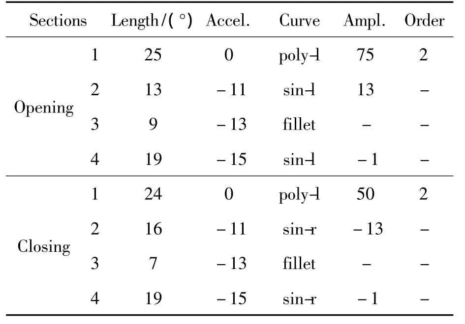
Table 8.Parameters for intake cam
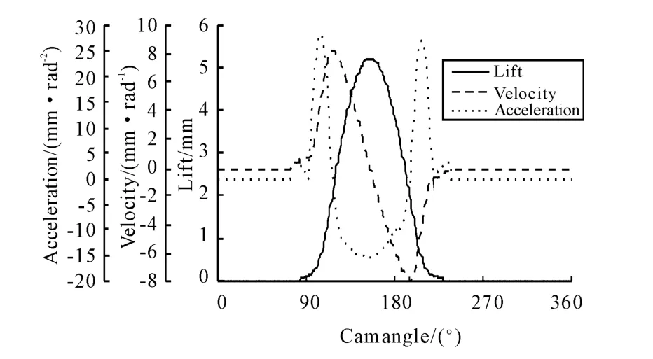
Figure 15.Valve lift,velocity and acceleration for two-stroke intake cam
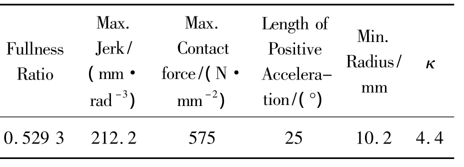
Table 9.The kinematic parameters
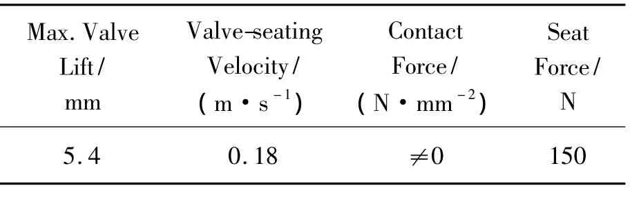
Table 10.The dynamics parameters
4.2.Exhaust cam profile design
Design parameters of opening and closing section for exhaust cam of two-stroke cam are shown in Table 11.
Kinematics evaluation results are shown in Figure 16 and Table 12.All of the parameters meet the design requirements and the valve gear operates stably in the crankshaft speed of 2 000 r/min.Dynamic evaluation results are shown in Table 13,and all of the parameters meet the dynamic design requirements in this speed.
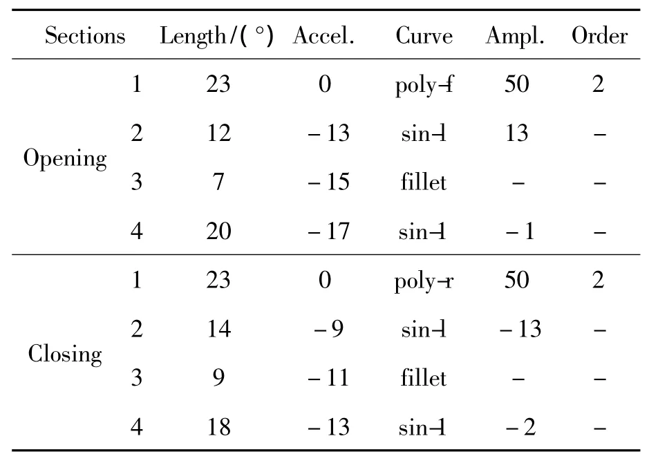
Table 11.Parameters for exhaust cam
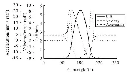
Figure 16.Valve lift,velocity and acceleration for two-stroke exhaust cam
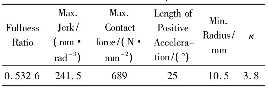
Table 12.The kinematic parameters
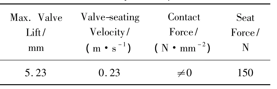
Table 13.The dynamics parameters
5.Conclusion
Through analysis and comparison of POL and STAC method for VCRPE four-stroke cam profile design,it shows that the STAC cam design method has the advantages in cam optimization design,and it can match the cam design requirement flexibly.STAC method is used respectively to design the intake and exhaust cam profile for VCRPE four-stroke and twostroke mode,the optimized cam profile through analysis of the kinematics and dynamics simulation results meet all design requirements and valve gear operated stable,which reach the expected purpose.Solid-Works is used to simulate the multi-body dynamics performance for corresponding VCRPE valve gear,and the dynamics simulation results of Excite_TD and SolidWorks are consistent with each other,which verifies the rationality of cam optimization design.
[1] Ricardo.Engine uses two and four stroke[J].Professional Engineering,2008(9):55.
[2] Baccile A,Ceccarini D,Cheng L,et al.An innovative control system for a 2/4 stroke switchable engine[J].SAE paper 07011199,2007.
[3] Di L M.Study on multiple working mode of reciprocating piston engine[D].Haerbin:Northeast Forestry University,2006.
[4] Di L M,Yang C J,Zhao Y S.Mathematical Model for Closed-form Solution of Parameters of Cylinder Exhaust Port in Variable-stroke Engine[J].Advanced Materials Research,2010,97:2724-2727.
[5] Feng R H.Optimized improvement design of the engine valve gear[D].Changsha:Hunan University,2009.
[6] David J W.Optional design of high-speed valve gear systems[C].SAE paper 94250,1994.
[7] Cardona A,Geradin M.Kinematical and dynamic analysis of mechanical with cams[J].Computer Methods in Applied Mechanics and Engineering 1993,103:115-134.
[8] Adametal M.Application of numerical simulation for the analysis of the dynamic behavior of valve gear system[J].International Journal of Vehicle Design 1990(1): 281-29l.
[9] Roland E.Advanced optimization techniques in valve gear design[C].SAE paper 982004,1998.
[10]Ademar R F.Procedure to modification of a camshaft profile[C].SAE paper 942407,1994.
[11]Li Z D.Research on the valve timing technology of variable stroke engine[D].Qinhuangdao:Yanshan University,CHINA,2010.
[12]Shang H J.Design and calculation of engine valve gear[D].Shanghai:Fudan University Press,1988.
[13]Sun J.Optimization design of polynomial dynamic cam for 475 diesel engine[J].Small Internal Combustion Engine and Motorcycle,2003,32:20-21.
[14]Zhang G C.Dynamics analysis and cam profile optimization design of the diesel engine valve gear[D].Tianjin: Tianjin University,2009.
[15]Ye H F,Hao Z Y,Guo L,et al.Design of unsymmetrical cam profiles for a high speed diesel engine with side mounted camshaft[J].Chinese Internal Combustion Engine Engineering,2010,31:25-29.
[16]Li H Z,Yuan Z C,Le J B,et al.Development of valve cam design[J].Chinese Internal Combustion Engine Engineering,1989,10:32-37.
可变循环往复活塞式发动机凸轮型线优化设计*
邸立明†1,孙万利2,师 颖3,王文峰1
1燕山大学车辆与能源学院,河北秦皇岛066004;
2沈阳佳实司法鉴定所,沈阳 110023;
3交通运输部公路科学研究院,北京 100088)
利用Excite_TD软件构建了本田125 mL单缸四冲程汽油机配气机构运动学与动力学模型,通过分析多项动力加速度函数(POL)与分段加速度函数(ISAC)凸轮型线设计方法的性能指标,选择ISAC优化设计可变循环往复活塞式发动机(VCRPE)二冲程与四冲程工作模式的进、排气凸轮型线。为了验证凸轮型线设计的合理性,利用SolidWorks构建并分析了相应配气机构的多体动力学模型,对比Excite_TD和SolidWorks模型的动力学分析结果表明,两者分析数据吻合较好,验证了凸轮型线优化设计的准确性。
往复活塞式发动机;可变循环;配气机构;凸轮型线;优化设计
TK423.41
10.3969/j.issn.1001-3881.2014.06.003
2013-10-26
猜你喜欢
杂志排行

机床与液压的其它文章
- Investigation of helical ball micro milling with variable radial immersion*
- Numerical simulation of the double suction balance type screw compressor working process*
- Parameter optimization of electro-hydraulic proportionalsystem of PID based on the improved ant colony algorithm
- Flying cutter machining and cutter design based on the machining principle of cycloid rotational indexing
- Simulation of multi-modal control in electro-hydraulicposition servo-system*
- Optimal design and security verification of flying cutterbased on finite element analysis