Influence of Punch Shape on the Fracture Surface Quality of Hydropiercing Holes
2014-03-14TaoYangJingHaoGangLiuHaiBoSuXinPingChenYanBingQi
Tao Yang,Jing Hao,Gang Liu,Hai-Bo Su,Xin-Ping Chen,Yan-Bing Qi
(1.State Key Laboratory of Advanced Welding and Joining,Harbin Institute of Technology,Harbin 150001,China; 2.Xi'an Space Engine Factory,Xi'an 710100,China;3.Baoshan Iron&Steel Co.,Ltd,Shanghai 201900,China; 4.FAW-Volkswagen Automotive Co.,Ltd,Changchun 130011,China)
1 Introduction
The demand of hollow components increases as the concept of lightweight proposed these years and the hydroforming technology is an advanced manufacturing method for such members. The hydroforming technology has been widely used in aerospace,aviation,automotive and other industries with many advantages in terms of better structural integrity of the product, lightweight, production cost reduction,material saving,reduction in the number of joining processes and product reliability improvement[1-2].The manufacturing method of holes has attracted much attention as the wide use of hydroformed parts[3],such as hydroformed tubes.Manufacturing holes on tubes had been carried out in two methods in the past:one was punching in the stresswith dedicated metal punching die,of which the production efficiency was low,and the other one was punching without die,of which serious collapse was around the hole.What’s more,we can also manufacture holes by laser cutting with good quality,but the equipment is too expensive[4].
Hydropiercing technology is a piercing method by using the punch separating wall material under the liquid pressure support in the tube,which is developed on the basis of hydroforming technology[4-5].Hydropiercing is a cost-effective method for piercing holes in a hydroformed tubular structure and there is no die but liquid pressure within the tube which has a great advantage to solve the problem placing die in the tube and is difficult due to small internal size or curve axis[6-7].
The fracture surface quality of hydropiercing holes is important for that it affects the appearance and fatigue life of the part.There are many factors of fracture surface quality, such as the hydraulic pressure,the punch diameter,the tube properties,the punch speed and so on.These years,many research progresses about hydropiercing have been made at home and abroad.Han et al.investigated the effect of the hydraulic pressure,the punch diameterand the thickness of tube on the process of hydropiercing by finite element program DEFORM-2D[8].Liu et al.investigated the influence oftube properties on hydropiercing quality[9]. Choi[10]investigated the ffffects of tube material properties,punch diameter,tube wall thickness and internal pressure within the tube during piercing on the deformation behaviour both experimentally and mathematically. Shiomi[11]investigated the ffffects of internal pressure within the tube,punch speed,punch stroke on the warpage of the sheet and the edge drop around the hole with punchpush method,punch-recede method and punch-pushrecede method.
However,the effect of punch shape on the fracture surface quality ofhydropiercing holesis notable but few studies.In this paper,the effect of punch shape on the fracture surface quality of hydropiercing holes was investigated.
2 Hydropiercing Experimental Scheme
The principle of hydropiercing is shown in Fig.1 (a).High pressure fluid was put into a tube with round section and the round section was bulged into rectangular section.In this process,the punch closed to the tube wall,then kept a certain pressure liquid in the tube and the punch began to feed until punching completed,finally,the hole shape was obtained,as shown in Fig.1(b).In this experiment,20#steel tube of Φ76 mm outer diameter and 2.5 mm thickness was used as the original billet.

Fig.1 Principle of hydropiercing and tube of the hydropiercing
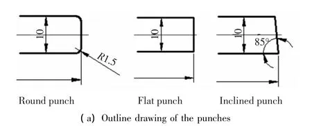
To investigate the influence of punch shape on the fracture surface quality of hydropiercing holes,three different shapes of punch were used,round punch with R1.5 fillet,flat punch without fillet,inclined punch with 5°sloping end face,and all of the three punches were cylindrical with diameter of 10 mm,as shown in Fig.2.


Fig.2 Outline drawing and photo of punches with different shape
3 Fracture Surface Quality of Hydropiercing Holes Punched by Different Punches
The fracture surface can be divided into four areas,collapse,smooth zone,tear zone and burr.The larger the size of smooth zone is,the better the fracture surface quality of hydropiercing holes is.The fracture surface quality ofhydropiercing holesaffectsthe appearance and fatigue life of the part.Therefore,the ratio of smooth zone should be increased.The photo of the fracture surface of hydropiercing holes is shown in Fig.3.This study is to investigate the influence of punch shape on the fracture surface quality of hydropiercing holes by comparing the collapse,smooth zone,tear zone and burr punched with different punches.

Fig.3 Macroscopic cross section of fracture of hydropiercing holes
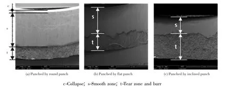
Fig.4 shows the micrographs of fracture surface punched by three different punches under 80 MPa internal pressure.It is clearly to see the collapse,smooth zone,tear zone and burr on the three fracture surfaces.The collapse punched by the round punch is a little larger than the other.The fracture surface quality punched by the round punch is good with larger smooth zone.The fracture surface exits a large gradient with concave and convex punched by the flat punch,which indicates the change is intense between the smooth zone and the tear zone during hydropiercing.The size of the smooth zone is smaller punched by the inclined punch and the size of the tear zone increases from the first fractured to the last fractured.The ratio of the smooth zone is nearly 75%,60% and 35% punched respectively by the round punch,the flat punch and the inclined punch.
The micrographs of the interface between smooth zone and tear zone punched by different punches under 80 MPa internal pressure are shown in Fig.5.The interface between smooth zone and tear zone is even with large gradient punched by the round punch.The interface between smooth zone and tear zone is uneven with large gradient punched by flat punch.The transition ofthe interface isuneven butsmooth punched by the inclined punch.

Fig.4 Micrographs of fracture surface punched by different punches

Fig.5 Interface between smooth zone and tear zone punched by different punches
The micrographs of fracture burr punched by different punches are shown in Fig.6.The results show that the tear phenomenon is obvious with small dimples but the burrs are not obvious punched by all the three punches for the high internal pressure.

Fig.6 Micrographs of fracture burr punched by different punches
4 Finite Element Analysis for Hydropiercing with Different Punches
Three-dimensional finite element simulation of hydropiercing with three different punches have been completed with ABAQUS in order to investigate the mechanism of the influence of punch shape on the fracture surface quality of hydropiercing holes by analyzing the distribution of stress and strain during the progress of hydropiercing.
4.1 Finite Element Modeling
The model was simplified to hydropiercing on a flat blank because hydropiercing was carried out on the tube wall with rectangular section in this study.Considering symmetry, quarter models of three dimensional solid were adopted in the modeling of hydropiercing punched by the round punch and flat punch and half model adopted in the hydropiercing punched by the inclined punch to reduce computation time.Assuming the die and the punch were discrete rigid shell body with R3D4 element type and the blank was deformable body with C3D8R element type.The element size of the area of fracture was small.The finite model of hydropiercing with inclined punch is shown in Fig.7.

Fig.7 Finite element models of hydropiercing with inclined punch
4.2 Damage Criterion
Ductile fracture phenomenon and damage criterion were investigated abroad at present.More than ten criterionsofductile fracture were proposed and investigated[12-14].The ductile fracture criterion is the key to simulate hydropiercing accurately.Wu et al.developed a 3D modelconsidering the effectof hydroforming implemented six ductile fracture criteria to predict crack initiation and propagation[15].Amir et al.performed 3D finite element simulations of the hydroforming,hydropiercing and wall extrusion using different damage criteria[7].In thisstudy,the material of the metal tube used in the experiment was 20#steel,which belongs to ductile metal,and hydropiercing is a progress of blanking major in shear stress,therefore,ductile initiation criteria and shear criteria from ABAQUS was adopted in this simulation.
Ductile fracture is the accumulation of damage due to the nucleation,growth,and coalescence of voids and the shear fracture is due to shear band localization.The ductile initiation criteria and shear criteria in ABAQUS are shown as Eqs.(1)and (2)[16].

The damage evolution law and element removal have to be defined after setting the damage initiation criterion.If one element meets the damage initiation criterion,the material stiffness is degraded according to the specified damage evolution law.When degraded to 0,the element removed and the crack generated.
4.3 Analysis of Stress and Strain of Hydropiercing
As shown in Fig.8,the simulation results show that the fracture burrs are not obvious punched by all the three punches.The collapse punched by the round punch is a little larger than the others.The fracture surface quality punched by the round punch and flat punch is good with larger smooth zone.The size of the smooth zone is smaller punched by the inclined punch.The transition of the interface between smooth zone and tear zone is uneven punched by the inclined punch.
As shown in Fig.9,the maximum principal stress of the blank contacted with the punch is negative punched by different punches,that is to say,the material is in a 3D compressive stress state.However,because the sharp blade of the flat punch and the inclined punch,stress concentration and shear band localization is very serious in the blank contacted with the side of the punch,where the equivalent plastic strain is also the maximum and the crack generated here firstly,as shown in Figs.10(b)and 10(c).There is no sharp edge on the round punch and the maximum equivalent plastic strain appears in the middle of the direction of thickness,as shown in Fig.10(a).

Fig.8 Fracture surface of hydropiercing simulation

Fig.10 Distribution of equivalent plastic strain before crack generating of hydropiercing
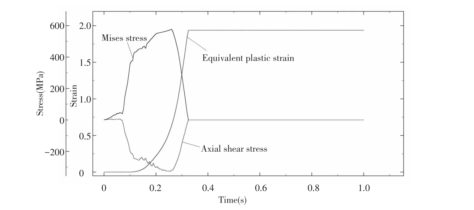
The axial shear stress,the Mises stress and the equivalent plastic strain of the first removed element punched by the flat punch during hydropiercing are shown in Fig.11.The absolute value of the axial shear stress and the Mises stress is increasing with the time before the stiffness degrading.When the element meets the damage initiation criterion,the absolute value of stress decreases,but the equivalent plastic strain still increases until the stress degrades to 0,at the same time,the element removes and the crack generates.

Fig.11 Stress and equivalent plastic strain of the first removed element punched by the flat punch
The Mises stress and the equivalent plastic strain of the first removed element punched by different punches during hydropiercing are shown in Fig.12.The change trend in three different punches is the same.The Mises stress firstly increases to the maximum,then drops to 0 before the crack generating.However,the damage of the hydropiercing punched by the round punch is later than others.The equivalent plastic strain increases with the punch downward before the element removed.The equivalent plastic strain punched by the flat punch is the largest and the equivalent plastic strain punched by the round punch is the smallest with the crack generating later.

Fig.12 Mises stress and equivalent plastic strain of the first removed element during hydropiercing
5 Conclusions
1)The fracture burrs are not obvious punched by all the three punches.The collapse punched by the round punch is a little larger than the other.The fracture surface quality punched by the round punch is good with larger smooth zone and the interface between smooth zone and tear zone is even with large gradient interface between smooth zone and tear zone.The size of the smooth zone is larger and the interface between smooth zone and tear zone is uneven with large gradient punched by the flat punch.The size of the smooth zone is smaller and the transition of the interface is uneven but smooth punched by the inclined punch and the size of the tear zone increases from the first fracture to the last fracture.
2)Different fracture surface quality will be obtained with different shape of punches.The reason is that the distribution of stress and strain is different and the cracks result in different time and location during hydropiercing punched by different shape of punches.
[1]Manabe K,Amino M.Effects of process parameters and material properties on deformation process in tube hydroforming.Journal of Materials Processing Technology,2002,123(2):285-291.
[2]Liu Gang,He Zhubin,Qi Jun,et al.Hydroformability evaluation of light-weight alloy tubes and manufacturing of tubelar components at elevated temperature.Forging&Stamping Technology,2008,33(3):48-51.
[3]Su Haibo,Liu Gang,Chen Xinping,et al.Influence of hydro-pressure inside tube on hydropiercing.Forging&Stamping Technology,2011,3:005.
[4] Wang Qiang,Teng Na,Cai Dongmei.Deformation mechanism of hydropiercing based on internal high pressure forming.China Mechanical Engineering,2006(17):63-66.
[5]Yuan Shijian.Modern Hydroforming Technology.Beijing: National Defence Industry Press,2009.194-200.
[6]Su Haibo,Jiang Haomin,Chen Xinping,et al.Application and research on hydro-piercing.China Metal Forming Equipment&Manufacturing Technology,2008(5):19-22.
[7]Hassannejadasl A,Green D E,Altenhof W J,et al.Numerical modeling of multi-stage tube hydropiercing.Materials and Design,2013,46:235-246.
[8] Han Cong,Yuan Shijian,Su Haibo,et al.Numerical simulation on hydro-piercing.The Chinese Journal of Nonferrous Metals,2006,16(1):22-28.
[9]Liu Gang,Lin Junfeng,Wang Gang,et al.Influence of tube properties on quality of hydropiercing.Transactions of Nonferrous Metals Society of China,2011,21(2):s456-s460.
[10]Choi S K,Kim W T,Moon Y H.Analysis of deformation surrounding a hole produced by tube hydro-piercing.Journal of Engineering Manufacture,2004,218(9):(1091-1097.
[11]Shiomi M,Ueda Y,Osakada K.Piercing of steel sheet by using hydrostatic pressure.Annals of the CIRP,2006,55 (1):255-258.
[12]Wierzbicki T,Bao Yingbin,Lee Young-Woong,et al.Calibration and evaluation ofseven fracture models.International Journal of Mechanical Sciences,2005,47(4-5):719-743.
[13]Hambli R,Reszka M.Fracture criteria identification using an inverse technique method and blanking experiment.International Journal of Mechanical Sciences,2002,44 (7):1349-1361.
[14]Ozturk F,Lee D.Analysis of forming limits using ductile fracture criteria. Journal of Materials Processing Technology,2004,147(3):397-404.
[15]Wu Zhigang,Li Shuhui,Zhang Weigang,et al.Ductile fracture simulation of hydropiercing process based on various criteria in 3D modeling.Materials and Design,2010,31(8):3661-3671.
[16]Abaqus Analysis User's Manual.http://docs.abaqus.com:8000/aoss-hdocs/v6.11/books/usb/default. htm.2013-08-01.
杂志排行
Journal of Harbin Institute of Technology(New Series)的其它文章
- Synchronization of High-order Discrete-time Linear Complex Networks with Time-varying Delays
- Research on Cloud Manufacturing Resource-Aware and Access Technology Using RFID
- Backstepping Adaptive Controller of Electro-Hydraulic Servo System of Continuous Rotary Motor
- Simulation Platform of Underwater Quadruped Walking Robot Based on MotionGenesis Kane 5.3 and Central Pattern Generator
- Numerical Simulation of High-Speed Water Entry of Cone-Cylinder
- Aerodynamic Characteristics of Projectile with Exotic Wraparound Wings Configuration
