Research on Cloud Manufacturing Resource-Aware and Access Technology Using RFID
2014-03-14MinLvChuanXiaZhouJiShuaiShiLeiLiu
Min Lv,Chuan-Xia Zhou,Ji-Shuai Shi,Lei Liu
(Dept.of Industrial Engineering,Harbin Institute of Technology,Harbin 150001,China)
1 Introduction
In the future, the development of the manufacturing industry will be more dependent on the network.For those enterprises that longing for occupying a position in the globalmarket,the virtualization and network of the manufacturing resources has become one of the essential conditions.Manufacturing resources refer to all hardware and software resources involved in the product life cycle,including the elements concerned with the research and development,production,sales,maintenanceand other activities,which can be mainly divided into equipment resources, material resources, human resources,computing resources, service resources, technical resources, customer information resources,applicationsystem resources and so on, being characterized by relative independence,autonomy,remote collaboration and the diversity of manufacturing performance.At present,China is the country with the most abundant manufacturing resources in the world,but these resources have not been fully utilized.The imbalance of the manufacturing resources and manufacturing capacities is common phenomena in the enterprise, causing the waste of manufacturing resources and manufacturing capabilities.However,in recent years,the gradual rise of cloud manufacturing technology has made up for these defects.The cloud manufacturing provides a new idea and mode for manufacturing informatization[1-2],namely integrating the rest of all kinds of manufacturing resources with information technology,as the further optimization of the collaborative manufacturing and grid technology[3].Providing customers with standardized service through virtualization technology can not only liquidize the stock of the manufacturing resources, optimize the configuration,improve the utilization rate of resources and reduce the resource cost of the whole society,but also let users use a variety of manufacturing resources just as using“water,electricity,coal and gas”,pushing our country's manufacturing industry to move along an evolutionary path towards “agile manufacturing”,“service-oriented manufacturing”,“green manufacturing”and“created-in-China”[4].
In the cloud manufacturing systems,how to embed the existing manufacturing resources and manufacturing capabilities into the cloud manufacturing service platform has become a key technology.The provider uses the Internet of things,virtualization technology and other technologies to sense discrete cloud manufacturing resources and manufacturing capacities,and accesses them to the cloud manufacturing platform,forming the virtual resource pool and providing to the receiving terminal in the form of services[5-6].After the in-depth analysis on thecloud manufacturing resources perception and access technology,a method to sense resources information based on RFID technology and access to the network system to support the cloud manufacturing was put forward and finally the application of the technology in the enterprise is given in this paper.
2 System Structure
Cloud manufacturing isbased on the cloud computing and expands concepts such as“Infrastructure as a service(Iaas)”,“Platform as a service(Paas)”,“Software as a service(Saas)”into“manufacture as a service”while cloud computing is to collect the software resources by the method of information and form the specialized services through offering users the redistributive combination[7].Referring to such model,the cloud manufacturing is to replace the software resourceswith manufacturing resources and manufacturing capacities in the cloud computing, namely integrating the manufacturing resources and manufacturing capabilities and redistributing them so as to offer users.
Cloud manufacturingsystem is a hierarchical architecture,as shown in Fig.1,mainly including physical resource layer,middleware layer,core service layer,portal layer and application layer.

Fig.1 Architecture diagram of cloud manufacturing system
Physical resource layer covers various resources concerned with the practical application,including equipmentresources, material resources, human resources,computing resources,service resources,technical resources,customer information resources and the application system resources,and accesses all kinds of physical resources to network through the Internet of things and cloud terminal access technology; Middleware layer converts various resources into virtual resources and releases them into the cloud manufacturing service center in clouds;Core service layer is all kinds of the virtual resources based on the middleware layer,to provide core services and function for the comprehensive management of cloud manufacturing services; Portal layer provides supporting platform and application interface for service providers,users and platform operators;Application layer faces all areas of manufacturing industry and users can search corresponding service according to their own needsthrough the portal layer.
The research scope of this paper mainly focuses on physical resource layer.Using RFID technology to sense cloud manufacturing resources is a non-contact automatic identification technology,which identifies the target automatically through radio frequency signal and gets the data carried.The identification is a process without human intervention.It can identify multiple electronic tags at the same time and RFID technology can access to all kinds of product data in the process of manufacturing promptly and accurately.The ultimate purpose of cloud manufacturing is to realize the informatization and servitization of manufacturing,and RFID technology can satisfy this requirement well.The hardware of RFID system is mainly composed ofthe reader and electronic tag[8-10],as shown in Fig.2.The reader encodes the information to be sent,and loads it to a carrier signal with a certain frequency and sends by the antenna.When the electronic tag receives the pulse signal in the reader work area,itwillcarry on the demodulation,decoding,decryption,and then judge the command request,password and privilege.If correct,it will carry on the corresponding read and write operations,otherwise return error messages.
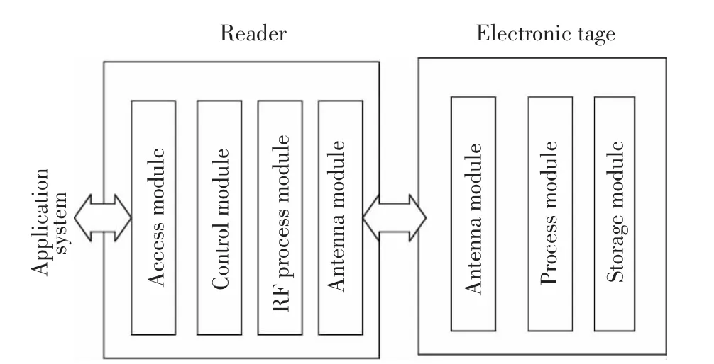
Fig.2 Composition of RFID system
The software mainly consists of front-end software,middleware,back-end software and others. The function of front-end software is to control the normal communication of the reader and electronic tag through the hardware device and back-end software,including read and write operations,collision technology,safety function and checking/correction functions; Middleware is the bridge of RFID hardware and application, mainly including application layer interface, event manager and reader adapter.Middleware deals with the large amounts of data collected by underlying device,provides the needed information for the application layer and accomplishes the filtering,aggregation,distribution,transmission and security of data as well as the management of the reader;Back-end software is designed according to customers’requirements,which is mainly composed of the data server and management terminal and responsible for communicating with the reader.The data processed by the middleware will be saved to the database of the background management system,and back-end software can realize the RFID systems management,electronic label management and data analysis and storage function.
3 Key Technology
The key technology of using RFID to sense cloud manufacturing resources mainly includes the following aspects[11]: anti-collision technology; Reader management techniques;Tag writing and labeling technology;Standards setting;Security and privacy; Middleware technology;Information identifying and coding technique,etc.This paper mainly makes a detailed introduction to the anti-collision technology and reader management technology.
3.1 Anti-Collision Technology
In the RFID system,the channel contention problem exists when multiple electronic tags run into the read range of the reader.Signals interfere with each other and form the so-called data collision,so as to cause the communication failure between the reader and electronic tag.According to the above problem,many correspondingsolutionshave investigated at present, common algorithms for anti-collision technology including ALOHA algorithm and binary search algorithm.ALOHA algorithm includes pure ALOHA algorithm and time slot ALOHA algorithm; while binary search algorithm includes ordinary binary search algorithm,dynamic binary search algorithm,the regressive index algorithm based on binary search algorithm and anti-collision algorithm based on jumping and dynamic searching.
The basic idea of pure ALOHA algorithm is when data encounter collisions in the process of sending data,the label will stop sending data and resend it again after a period of time;Time slot ALOHA algorithm is an improved pure ALOHA.On the basis of ALOHA algorithm,the time is divided into discrete time slots,and each length of time slot should be greater than the data length of label reply.Tags can only send data in each time slot.But this method requires a synchronous clock to make the reader read all tags within the scope of the time slot synchronization.
Fig.3 shows the curve of output rate and input load of the pure ALOHA algorithm and time slot ALOHA algorithm.According to Fig.3,the channel utilization ratio of pure ALOHA algorithm can reach 0.184.When the number of the label increases,its performance falls sharply,being prone to make errors in judgment.The algorithm is applied in the situation where real-time is not high.However,time slot ALOHA algorithm can reach 0.368,which is doubled that of pure ALOHA algorithm.

Fig.3 Curve of output rate and input load of the pure ALOHA algorithm and time slot ALOHA algorithm
The identification efficiency of the binary search algorithm is very high and almost has no misjudgment,with the channel utilization rate up to 0.43.The binary search algorithm and dynamic search algorithm need query log2n+1times when identifying n labels,while the regressive index algorithm and dynamic algorithm by leaps and bounds only require 2n-1 times.Though binary algorithm can identify tag quickly when the tag amount is large,it is easier to expose the information leading to the poorer security.
In the traditional time slot ALOHA algorithm,when the load is equal to 1,throughput rate reaches the maximum;when the load is less than 1,the number of empty slots can increase;when the load is more than 1,the number of collision time slot can increase,which will reduce the real-time character of the system.Cloud manufacturing resources perception puts forward higher requirements on real-time.Therefore, the traditional anti-collision algorithm cannot meetthe real-time requirements ofcloud manufacturing resources perception.According to the above situation,this paper proposes a dynamic frame contention slotALOHA algorithm.Thisalgorithm combines the optimization principle with the traditional ALOHA algorithm.By dynamically adjusting the transmission time slot and packet size,it can greatly reduce the incidence of the collision,improve the performance of the system,make the implementation become easier and achieve the relatively lower cost.
The thought of the algorithm is based on TDMA,a frame consisting of N time slots.TDMA(time division multiple access)method is a technology of allocating the available channelcapacity to multiple users according to the time[12-13].The tag selects a time slot to send data in each frame randomly,while time slot N in a frame changes along with the tag number in the reading area dynamically.It will increase the number of time slots to reduce collisions in the frame,or reduce the number in order to save time when there are a lot of empty slots.The schematic diagram of the algorithm is shown in Fig.4.

Fig.4 Schematic diagram of dynamic frame contention slot ALOHA algorithm
For the convenience of analysis,the following parameters are defined at first:Output rate Y,the total actual rate through effective transmission,namely the average frequency when the tags complete successful communication per unit time;The input load rate X=is the tag number identified by the Reader;N is the length of the frame.So the probability of a time slot identifying a label correctly is:

Taking the derivative of N:

So when n=N,Y reaches the maximum:

When N tends to infinity:

The step process of the algorithm is shown in Fig.5.
When the reader sends the command of identifying to start a new cycle,the new loop length N comes from the dynamic optimization adjustment according to the number of collisions in the previous cycle.

Fig.5 Flow chart of dynamic slot ALOHA algorithm
3.2 Reader Management Techniques
This paper takes C216018(9600)reader as a case to study the managementreader,a reader supporting ISO18000-6B and EPC GEN2 protocol standard.The SDK software development kit provides a secondary developmentofthe reader,meetsthe application needs of the protocol extension and function extension,and can be customized forthe user agreement.The management system function model of the reader is shown in Fig.6,including the system parameter setting,18000-6B function demonstration,EPC(GEN 2)function demonstration,EPC(GEN 2) card presentation,and EPC(GEN 2)card writing.
3.2.1 System parameter setting
1)Setbasic parameters:Basic parameters include manner of working, card read cycle,communication mode and trigger mode.Where,the manner of working includes the positive data sending,passive data sending and response mode. The communication mode includes RS232, Syris,Wiegand26,Wiegand34 and RS485;Trigger mode includes high level on,low level on and off.
2)Set Wiegand parameters:It is mainly related to the Wiegand output interface.When selecting communication mode is Wiegand way,it is effective.Setting Wiegand parametersincludes data offset,output cycle,pulse width and pulse period.Data migration refers to the card’s number of bytes to offset.
3)Set frequency parameter:Frequency can be divided into the fixed frequency and frequency hopping,related to 18000-6B and EPC(GEN 2).Generally we choose frequency hopping.
4)Same ID output parameters:When the reader reads a label many times continuously,it can only upload a set of data.
3.2.2 18000-6B function demonstration
Tag identification searches tags within the scope of antenna recognition and reads their 8 byte of UID; reading tag refers to reading the data length in the specified starting address;writing tag refers to writing certain bytes of data in the specified starting address.18000-6B is an 8-bit of storage format,so every time to read and write is one byte.
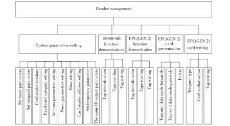
Fig.6 Function model of reader management system
3.2.3 EPC(GEN 2)function demonstration
Tag identification searches tags within the scope of antenna recognition and reading their EPC;reading tag refers toreadingthe tag’sEPC,choosing the corresponding block and reading the data length in the specified starting address;writing label refers to writing label’s EPC,choosing the corresponding block and writing certain bytes of data in the specified address.EPC is a 16-bit storage format,so every time to read or write is two bytes.
3.2.4 EPC(GEN 2)many cards presentation
When reading card category is set to the EPC (GEN 2)card option,this function is effective.The work mode is set.
3.2.5 EPC(GEN 2)write a card
Wiegand type includes Wiegand26 and Wiegand34.When the card number is written,decimal and hexadecimal number are automatically conversed.So it only needs to fill in a data base.Only after inputting authorized password,the user can write card.
After software is connected to the reader,we can deal with the parameter setting and function presentation on the reader.The function library of reader is Microsoft Windows interface standard.It can support the development tool of VC,VB,VF,Delphi,C++Builder and Power Builder,etc.Main functions include open/close the serial port,reading the device serial number,identification card number,writing data,reading data,setting the work mode,etc.Specific functions are as follows:
1)int_stdcallOpen_Port(unsigned char port): open serial port;
2)int_stdcallClose_Port(unsigned char port): close serial port;
3)int_stdcallReadSerialNum(unsigned char port,int*Serial_Num):read the device serial number;
4)int_stdcall Identify_6B(unsigned char port,intSerial_Num,unsigned char*buf):identify 18000-6B card number;
5)int_stdcall Read_6B(unsigned char port,intSerial_Num,unsigned char*buf,unsigned char addr,unsigned char len):read 18000-6B data;
6)int_stdcall Write_6B(unsigned char port,intSerial_Num,unsigned char*buf,unsigned char addr,unsigned char len,unsigned char*data):write in 18000-6B data;
7)int_stdcallSettingPara(unsigned char port,intSerial_Num,unsigned char*buf,unsigned char* data,unsigned charlen):set the work mode;
Suction parameter:
Port:Serial Port Number,0-serial port 1,1-serial port 2,by parity of reasoning;
Serial_Num:Device serial number;
Buf:In the receiving card information,if the sixth byte is 1,it means writing card successfully, otherwise fail.
Addr:Address; Len:Data length;
Data:Data pointer address;
4 Application Research
Theoretically speaking, to apply RFID in extracting all kinds of product data information during the productwhole life cycle managementisthe development trend of the future[14-15].This trend will promote cloud manufacturing into a new development platform-intelligent,agility,green manufacturing.But because of non-uniform the price of electronic tag and standard,only a few companies use this technology.With the improvement of RFID technology,large-scale application ofRFID electronic tagsforresources perception will vigorously promote the development of cloud manufacturing technology.
4.1 System Hardware Structure
Compared with the more mature process enterprise,there is a large gap for discrete manufacturing enterprise management.The characteristic of discrete enterprise is made to order,which puts forward a higher request on the information management of product.According to the above situation,combined with the actual situation of an enterprise,this paper proposes a designing scheme of key-module tracking management system in discrete manufacturing enterprise.In this enterprise the keymodule machining environmenthas the following features:greasy dirt,more dust and larger noise,longer processing cycle,more frequent replacement of tools,and faster update of data.The traditional bar code technology is strict to the environment,cannot be used for data dynamic updating,and cannot be used in the environment of poor processing workshop;the code of surface acoustic wave technology is developed by manufacturer at a time.The data cannot be updated dynamically and affected by the environment.The above two solutions cannotmeetthe needs of enterprises.RFID technology is characterized by the well adaptation to the environment well,supporting readingthe remote data,all-weatherwork,and recording the production data in real time,which meets the requirements of dynamic management of keymodule manufacturing process in the discrete manufacturing enterprise.The scheme is to use RFID electronic label to track products.The RFID electronic tag is bound on raw materials when it comes into the factory to track and manage the full life cycle of product manufacturing in time.According to the actual demand of enterprise,we choose reader C216018 (9600).Its frequency is 900 MHZ.It can read 1 to 6 meters away,has an ability of Waterproof,dustproof and anti-interference,and has an 8dBi high-gain circularly polarized antenna.Tag selects passive uhf passive tags.Each product has a serial number when it comes into the factory,so the system sets out a 64-bit encoding scheme.Swimlane diagram of the system is shown in Fig.7.
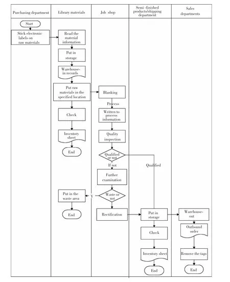
Fig.7 Swimlane diagram of the system
In the processing workshop,the process of material processing is being followed by the RFID reader which is set up on each station.When the label arrives at a station,controller uses the reader and the antenna to record processing working procedure,equipment,the number of workers,processing time and other information automatically,then transmits them to the database and saves in the enterprise information management system.So managers can track product quality and quantity in time,issue the production order and operation guide by electronic display board and carry out the processing process management and warehouse management.At the same time,the shared resources can be released to the cloud,such as inventory information,enterprise introduction,equipment management information,tool managementinformation, and partofprocessing information,etc.While enterprise’s independent intellectual property rights confidential information,key process information, and part of the quality information are published to the Intranet for sharing.Information that can be released to the cloud is gathered to the cloud manufacturing service platform for the cloud user on demand after processed by using virtualization technology. The network topology of the system is shown in Fig.8.

Fig.8 The network topology of the system
The underlying RFID reader is responsible for collecting the information in the electronic label and dealing with the simple information pretreatment.The middleware dealswith thisinformation,such as filtration,classification and anti-collision,which is packed and uploaded to the company's management.Managers decide whether to put the information on the cloud service platform for the use of demand side.Meanwhile through the analysis of field data in real time,managers make reasonable decision,plan and guidance in time and pass to the operating personnel through the electronic board.The connection among server,controller and reader is RS485.The connection between centralserver and network interface is industrialEthernet,which forms a starnetwork structure.The business management is at the top of the system, namely the external interface. Central server is the dispatching center.It integrates and releases production and storage information, realizing the company internal and external information sharing.
4.2 Information Structure of the System
Information flow in the enterprise is shown in Fig.9.According to the requirements and forecast reports of warehouse department,the purchasing department releases the purchase order.According to the purchase order,the supplier delivers the goods and puts in storage;according to production plan,the processing workshop picks up the goods from the warehouse for processing.After the processing,the finished product or semi-finished products are sent to the warehouse.Meanwhile,the feedback of the processing information is to the management department;the sales department picks up the goods according to orders.Basic data management runs through the process.
The system uses VB to design the interface and SQL Server 2005 database system to store product information.In VB development environment,the system uses ODBC(Open Database Connectivity)to link database.This paper carries on the function analysis on the basis of the overall mission which has developed.The function structure diagram of the system is shown in Fig.10.
According to the requirement of the designed system function and the division of function modules, this paper has carried on the demand analysis to the database and conception framework design,developed the function interface,as shown in Fig.11 and implemented product perception and access to physical resources successfully,which makes the enterprise inventory management,processmanagement,and other more accurate,timely and convenient.
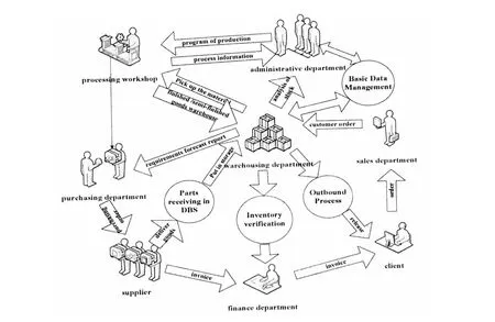
Fig.9 Enterprise's information flow
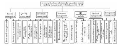
Fig.10 Function structure diagram of the system
The designed scheme in this paper is mainly used for discrete manufacturing enterprises to supervise and control the whole life cycle of product.According to the application in key-module processing and inventory management,the solution achieves ideal effect on the loading and unloading efficiency and accuracy as well as on the processing of information extraction and record.The number of inventory managers reduces to 8 persons compared with previous 11 ones.Production life cycle is shortened by 15%.The rate of leak and fault detection is reduced by 80%.So it is proved that the system is feasible and effective.

Fig.11 The function interface
5 Conclusions
With the development of network information technology,the cloud manufacturing technology will become the key technology of manufacturing.RFID-based resource perception and access technology proposed in this paper makes full use of the advantage of RFID technology,which can not only improve the enterprisemanagementefficiency and management quality,but also make the enterprise resources be shared in the network system.It provides powerful support for the enterprise information management.
[1]Li Bohu,Zhang Lin,Wang Shilong.Cloudmanufacturingservice-oriented networked manufacturing new model.Computer Integrated Manufacturing System,2010,16(1): 1-7.
[2]Jia Kai.Service oriented,efficient,low consumption,new mode of the agile manufacturing based on the network.Manufacture Information Engineering of China,2011,20 (2):10-14.
[3]Wang Guoqing,Wang Gang,Lv Min.Cross-enterprise collaborative manufacturing platform research based on grid.Journal of Harbin Institute of Technology,2007,33 (11):1723-1726.
[4]Li Bohu,Zhang Lin,Chai Xudong.Overview of cloud manufacturing.ZTE Communications Technology,2010,16(4):5-8.
[5]He Dongjing,Song Xiao,Zhang Lin,et al.Coordination of complex product design framework based on cloud services.Computer Integrated Manufacturing Systems,2011,17(3): 867-876.
[6] HuangShenquan.On-DemandSupplyMode,Key Technologies and Application ofManufacturing Cloud Service.Hangzhou:Zhejiang University Press,2013.21-26.
[7]Buyya R,Yeo C S,Venugopal S.Cloud Computing and Emerging IT Platforms:Vision,Hype,and Reality for delivering Computing asthe 5th Utility.Melbourne: University of Melbourne Press,2009.78-83.
[8]Zhao Junhui.Radio Frequency Identification Technology and Application.Beijing:Mechanical Industry Press,2008.5-8.
[9]Xu Xuehui.Study on the Anti-Collision Algorithm in Radio Frequency Identification Technology.Wuhan:Huazhong Normal University Press,2006.35-40.
[10]Du Yunming,Zhou Yang.Radio frequency identification technology and application research. Techniques of Automation and Applications,2010,21(5):52-55.
[11]Kwon I.A single-chip CMOS transceiver for UHF mobile RFID reader.IEEE Journal of Solid State Circuits,2008,43(3):729-738.
[12]Kang Dong,Shi Xiqin,Li Yongpeng.RFID Core Technology and the Typical Application Cases.Beijing: People’S Posts and Telecommunications Press,2008.43-48.
[13]Wei Feng.Research on Key Techniques of Long-Range Radio Frequency Identification System.Xi'an:Xidian University Press,2009.55-61.
[14]Ni L M,Zhang D,Souryal M R.RFID-based localization and tracking technologies.IEEE Wareless Communications Magazine,2011,18(2):45-52.
[15]Chen J C,Cheng Chenhuan,Wang Kungjeng,et al.Application ofRFID towarehousemanagement.Key Engineering Materials,2011,1367(486):297-303.
杂志排行
Journal of Harbin Institute of Technology(New Series)的其它文章
- Aerodynamic Characteristics of Projectile with Exotic Wraparound Wings Configuration
- Numerical Simulation of High-Speed Water Entry of Cone-Cylinder
- Intelligent Temperature Control System Design Based on Single-Chip Microcomputer
- Influence of Punch Shape on the Fracture Surface Quality of Hydropiercing Holes
- Synchronization of High-order Discrete-time Linear Complex Networks with Time-varying Delays
- Simulation Platform of Underwater Quadruped Walking Robot Based on MotionGenesis Kane 5.3 and Central Pattern Generator
