A Fully Differential Interface Circuit of Closed-loop Accelerometer with Force Feedback Linearization
2014-03-14HongLinXuHongNaLiuChongHeLiangYinXiaoWeiLiu
Hong-Lin Xu,Hong-Na Liu,Chong He,Liang Yin,Xiao-Wei Liu,2
(1.Micro-Electromechanical System Center,Harbin Institute of Technology,Harbin 150001,China; 2.Key Laboratory of Micro-Systems and Micro-Structures Manufacturing,Ministry of Education,Harbin 150001,China)
1 Introduction
Σ-Δ modulation is widely applied in analog-todigital(A/D)in thearea oflow-speed highresolution[1].High-precision ΣΔ ADCs based on ΣΔ modulation technology are easy to be integrated into the digital chip,and less sensitive to the mismatch of device.Because of that,Σ-Δ modulation technique has been recently used in micro-electromechanical systems(MEMS), such asaccelerometersand gyroscopes. Great quantities of low-cost, high reliability of micro-accelerometers are widely used in civil and military fields[2]. High-precision accelerometers are attractive in inertial navigation and guidance,microgravity measurements in space,tilt controland platform stabilization,and GPS-aided navigators for the consumer market[3-5].
Micromechanical Σ-Δ accelerometer which provides a direct digital output is advantageous in linearity,dynamic range and bandwidth[6].Previous work focused on the stability and low noise,and recently a few papers reportthe research of high-order architecture of accelerometers[7-9].However,most of the accelerometers are limited to the Brownian noise.Micromechanical accelerometers with high mechanical quality factor(Q) are lower in thermal-mechanical Brownian noise and superior in dynamic range,while the stability is one key limitation for the application of high-order accelerometers.Another important problem is the harmonic distortion analysis for the Σ-Δ sensors.The conventional way to detect the dynamic specialty is to use a shaker table.However,the precision of shaker table is usually less than 0.003%,so the distortion within the vibration table limits the distortion measurement[10-11].
This paper proposes a fully differential closed-loop high-order low noise Σ-Δ accelerometer with a high-Q mechanical transducer.A lead compensator is adopted to ensure the stability of the high-order system.In the meanwhile,a low noise capacitance detection circuit is presented with a correlated-double-sampling(CDS) technique.To detect the dynamic specialty of the sensor,a self-test technique is applied here.In addition,to improve the linearity and DR of the accelerometer,a force feedback linearization circuit is proposed here.
2 System Design
A fifth-order feedforward and distributed-feedback topology(DFFF)is presented for micromechanical ΣΔ accelerometer in Fig.1. This topology is advantageous in a larger input range and a lower integrator output swing[6].This topology consists of micromechanical transducer, displacement-voltage conversion, lead compensator and third-order modulator. The second-order micromechanical transducer is simplified as

where m is the proof mass and k is the spring constant.In Eq.(1),the resonant frequency woand quality factor Q is described with the damping coefficient b as follows:

The displace-voltage conversion is considered as a linear gain factor ignoring nonlinearity.The lead compensator is described in z-domain shown as:

where α in Eq.(2)is the compensation factor which compensates the second-order micromechanical transducer to obtain sufficientstability margin[9].However,a large α results in deep compensation for the system with low loop gain and reduces the ability of noise shaping[12].The third-order modulator includes two delayed integrators,one non-delayed integrator and 1-bit quantizer.The electrostatic feedback based on time shared multiplexingprincipledoes notneed electrostatic performer electrode,which denotes that electrostaticfeedback and charge sensitization are accomplished in different phases of one cycle,which greatly eliminates feedthrough between feedback signal and pick-up charge signal.The discrete-time response of mechanical transducer to a single feedback pulse for time shared multiplexing principle isthe transfer function given in Eq.(3)where zmand zm*are two poles of the mechanical transducer,and bfis the zero and kfis the gain factor.

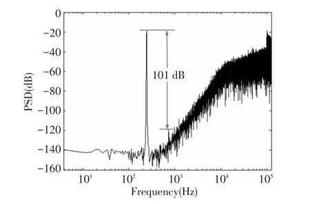
In this paper,the parameters of mechanical transducer depend on the accelerometer sensor provided by Colibrys.In the models ofFig.1,an equivalent0.8 g sinusoidal signal centered at 244.14 Hz is applied as a simulated acceleration input.The digital output sequence of proposed fifthorder micromechanical Σ-Δ accelerometer is calculated to obtain the output power spectral density(PSD),as shown in Fig.2.The result indicates that the noise floor is about-140 dBV/Hz1/2at low frequency and obtains 101 dB third-order harmonic distortion detection based on a linear displace-voltage conversion.

Fig.1 Proposed fifth-order DFFF topology for micromechanical Σ-Δ accelerometer

Fig.2 PSD for the micromechanical Σ-Δ accelerometer
3 Circuit and Layout Design
Fig.3 shows the proposed interface circuit for the accelerometer.The sensitization capacitance Cfis 10 pF,and the reference capacitance and the static capacitance of the mass and electrode are both 180 pF.The CDS and hold capacitances are 5 pF.The CDS and hold cell consists of resistor R,capacitors Ccand CH,switches S7and S8,and amplifiers A2and A3.The switch S8is a short pulse and the CDS technique is to decrease 1/f noise and offsetofthe operational amplifier(op-amp)of the sensitization part.The fully differential amplifier of the sensitization part is the core of the proposed interface which should have the property of low noise.The op-amp has a foldedcascode topology with a continuous-time common-mode feedback circuit.The input-referred noise mostly caused by the input transistors is eliminated by the CDS technique.The other op-amps are less critical than the sensitization part.The electrostatic feedback and charge sensitization are accomplished in different phases of one cycle, which greatly eliminates feedthrough between feedback signaland pick-up charge signal.
The lead compensator and control clock are shown in Fig.4.The circuit in Fig.4 describes a function as follows:

where assuming C1n=C1p=C1,C2n=C2p=C2,C3n=C3p=C3.If C1=C3and C2=αC3,then


Fig.3 Circuit diagram of the proposed micromechanical Σ-Δ accelerometer

Fig.4 Circuit diagram of the lead compensator
Heavy lead compensation is required to ensure the stability of the high-order system with high Q sensor element.If the compensation is insufficient or the loop gain is too high,the closed-loop system turns to be unstable.Otherwise,the system is unstable when the loop gain istoo low fora heavily compensated micromechanical Σ-Δ accelerometer[9]. As the quantizer and the feedback circuit are nonlinear,the accelerometer interface isstrongly nonlinear.The signal magnitude influences the loop gain.If the input signal magnitude is too low,the loop gain becomes very high resulting in an unstable system.A high input signal magnitude also makes the feedback system unstable due to the small loop gain.The integrator and quantizer become overloaded simultaneously.
Although a heavy compensation factor ensures a stable high-order system,it decreases the loop gain and noise shaping ability.The vacuum packaged Colibrys sensor has a high DC gain and needs a heavy compensation factor to ensure a stable high-order system,and the compensation factor α is 0.9 through simulation verification.The noise of the sensitization part can be reduced by the CDS technique,while the compensator circuit should be designed carefully to gain a low noise without the use of noise reduction technology.
Fig.5 shows the third-order modulator which is applied in Fig.3 to obtain a high-order system to make sure a good noise shaping ability[13-14].The modulator combined with the front end circuit realizes the fifthorder DFFF micromechanical Σ-Δ accelerometer presented in Fig.1.The self-test technique is to measure distortion without using vibration table which involves distortion larger than 0.003%[15].The selftest circuit for the high-order Σ-Δ accelerometer is presented in Fig.5.Selecting the first integrator as the input of self-test will make a maximum dynamic range.The second integrator is not the best choice because of the great loss of signal gain,and the poles of the system will be changed by applying the self-test to the input of third integrator.

Fig.5 Third-order modulator applied in Fig.3
It has been proved that the nonlinearity of the electrostatic force feedback is loop gain times the integrator.When loop gain of the system is very large,the integrator nonlinearity can be ignored compared with the electrostatic force feedback[2].The ideal 1-bit electronic DAC islinear,butfora mechanical accelerometer,the conversion of a voltage to an electrostatic feedback force on the proof mass by the DAC is nonlinear which depends on the residual proof mass motion and is described as[16]:

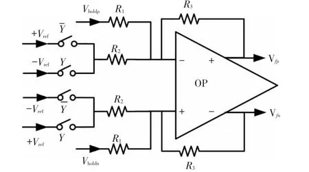
where Vrefis the reference voltage;Vfis the feedback voltage;x is the proof mass motion;d0is the static distance between the proof mass and the electrode,and C0is the static capacitance of mass and electrode.Eq.(4)indicates that there are higher harmonic contents relating to the mass motion,so to reduce the harmonic contents will result in a better performance for the sensor system.To reduce the nonlinearity of the electrostatic force feedback, a force feedback linearization circuit is presented in Fig.6 to reduce the harmonic distortion which will achieve a larger dynamic range for the accelerometer sensor.
In Fig.6,the feedback voltage Vfcan be rewritten as:

where Vdisis hold voltage of the displace-voltage conversion,and is given by:


Fig.6 Electrostatic force feedback linearization circuit
If R3=R2and,then:

Combining Eqs.(4)and(6),the electrostatic feedback force is changed to

It is obvious that the feedback force is independent of the mass motion,and the higher harmonic contents of Eq.(4)are eliminated.
The layout of the accelerometer IC is implemented in a standard 0.6 μm CMOS technology,and the active circuit area is about 7.8 mm2as shown in Fig.7.

Fig.7 Layout of the sensor IC
4 Results and Discussion
The post-simulation of the layout is achieved at a sampling clock of 250 kHz with a 5 V supply.The power consumption is 20 mW.To prove the validity of the design principle,a sinusoidal signal worked at 244.14 Hz is applied to the self-test input,and the amplitude is 150 mV.Fig.8 shows the PSD of the postsimulation output sequence of the IC calculated by Matlab without the electrostatic force feedback linearization.The result indicates that the noise floor of the proposed selftest function is about-140 dBV/Hz1/2in the bandwidth of 800 Hz,and the sensitivity is 2.5 V/g.However,the third-order harmonic distortion is 89 dB.Fig.9 showsthe self-testresultwith electrostatic force feedback linearization. To test the linearization function of the electrostatic force at the same condition,the amplitude of the self-test voltage remains the same.From the PSD plot presented in Fig.9,a 98.2 dB third-order harmonic distortion is gotten,and the second-order harmonic distortion disappears.The interface achieves a SNDR of 93 dB simultaneously.

Fig.8 Self-test result without force feedback linearization
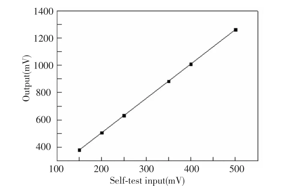
To vary the amplitude of self-test voltage from 150 mV to 500 mV,the output amplitudes of the accelerometer are shown in Fig.10.Of course,the input amplitude range ofthe self-testisbeyond 150 mV-500 mV.The nonlinearity of the self-test result is calculated as low as 0.11%based on the data in Fig.10.

Fig.9 Self-test result with force feedback linearization

Fig.10 Relation between amplitudes of self-test input and output
5 Conclusions
This work presents a fifth-order fully differential closed-loop DFFF topology Σ-Δ interface circuit with a high-Q mechanical transducer.Thesystem model analysis and circuit design are given in detail.A heavy compensation factor is adopted to ensure the stability of the high-order system.To avoid vibration table for the test of accelerometer sensor,a self-test technique is presented to measure distortion in this paper.The postsimulation results show that the sensor system is stable and has an 89 dB third-order harmonic distortion.To reduce the distortion caused by electrostatic force feedback nonlinearity,a linearization circuit for the sensor is given and the self-test result with linearization function shows a 98.2 dB third-orderharmonic distortion without the second-order harmonic distortion.The proposed linearization technique achieves 0.11% nonlinearity with the sensitivity of 321 mV/g.The power consumption is 20 mW with a 5 V supply at 250 kHz samplingfrequency.Thepost-simulation results confirm that the self-test and linearization technique are effective and agree with the design principle.
[1]Candy J C,Temes G C.Oversampling Methods for A/D and D/A Conversion.Oversampling Delta-Sigma Data Converters:Theory,Design and Simulation.New York: IEEE Press,1992:1-3.
[2]Liu X W,Xu H L.Nonlinearity analysis of a closed-loop ΣΔ micro-mechanicalaccelerometer.Key Engineering Materials,Micro-Nano Technology XIV,2013,562-565: 380-386.
[3] KülahH,NajafiK,ChaeJ.Noiseanalysisand characterization of a Sigma-Delta capacitive microaccelerometer.IEEE Journal of Solid-state Circuits,2006,41(2):352-361.
[4]Seok S,Kim H,Chun K.An inertial-grade laterally-driven MEMS differential resonant accelerometer.Proceedings of IEEE Sensors 2004.Piscataway:IEEE Press,2004.654-657.
[5]Chang D,Kubena T R L,Stratton F P.Wafer-bonded,high dynamic range,single-crystalline silicon tunneling accelerometer. Proceedings ofIEEE Sensors 2002.Piscataway:IEEE Press,2002.860-863.
[6]Dong Y F,Kraft M,White W R.Higher order noiseshaping filters for high-performance micromachined accelerometers.IEEE Trans. Instrumentation Meas.,2007,56(5):1666-1674.
[7] Kollar M, MichaeliL. Noise consideration for micromachined digital accelerometers.Proceedings of the IEEE Instrumentation and Measurement Technology Conference.Piscataway:IEEE Press,2006.507-512.
[8]Sonmez U,Kulah H,Akin T.A fourth order unconstrained ΣΔ capacitive accelerometer. Proceedings of 16th International Conference on Solid-State Sensors,Actuators and Microsystems.Piscataway:IEEE Press,2011.707-710.
[9]Wu J F,Carley L R.Electromechanical ΔΣ modulation with high-Q micromechanical accelerometers and pulse density modulated force feedback.IEEE Trans.Circuits Syst.I,Regular Papers,2006,53,(2):274-287.
[10]Jeffery G.A seismic test facility.Meeting of the Society of Exploration Geophysicists. New Orleans:Society of Exploration Geophysicists,1999.1-3.
[11]Goldberg H.An extremely low-noise MST accelerometer using custom ASIC circuitry.Proceedings of sensor Expo Fall 2000.Detroi:Sensor Expo,2000.479-482.
[12]Liu Yuntao.Research on Interface AISC for Capacitive Sigma-delta Accelerometer.Harbin:Harbin Institute of Technology,2010.
[13]Almutairi B,Michael Kraft.Multi stage noise shaping sigma—delta modulator(MASH)for capacitive MEMS accelerometers.Sensors and Actuators A,2012,186: 169-177.
[14]Yücetaş M,Pulkkinen M,Kalanti A.A high-resolution accelerometer with electrostatic damping and improved supply sensitivity.IEEE Journal of Solid-state Circuits,2012,47(7):1721-1730.
[15] Liu Yuntao,Yin Liang,Chen Weiping.Design of interface circuit of closed-loop accelerometer with self-test function.Optics and Precision Engineering,2009,17 (6):1379-1384.
[16]Dong Y F,Kraft M,Redman-White W.Force feedback linearization for higher-order electromechanical sigma-delta modulators. Journal of Micromechanics and Microengineering,2006,16(6):54-60.
杂志排行
Journal of Harbin Institute of Technology(New Series)的其它文章
- Influence of Punch Shape on the Fracture Surface Quality of Hydropiercing Holes
- Backstepping Adaptive Controller of Electro-Hydraulic Servo System of Continuous Rotary Motor
- Simulation Platform of Underwater Quadruped Walking Robot Based on MotionGenesis Kane 5.3 and Central Pattern Generator
- Synchronization of High-order Discrete-time Linear Complex Networks with Time-varying Delays
- Numerical Simulation of High-Speed Water Entry of Cone-Cylinder
- Aerodynamic Characteristics of Projectile with Exotic Wraparound Wings Configuration
