Patrol inspection system of underground cable joint fault based on wireless communication*
2014-03-09XiaochangYOULeiLI
Xiao-chang YOU,Lei LI
1School of Mechanical Engineering,Chongqing Industry Polytechnic College,Chongqing 401120,China;
2College of Automation,Chongqing University,Chongqing 400044,China
Patrol inspection system of underground cable joint fault based on wireless communication*
Xiao-chang YOU†1,Lei LI2
1School of Mechanical Engineering,Chongqing Industry Polytechnic College,Chongqing 401120,China;
2College of Automation,Chongqing University,Chongqing 400044,China
The temperature is an important parameter reflected by operating condition of power network.Aimed at the puzzle of being difficulty to inspect the fault of underground cable joint,the paper explored a sort of patrol inspection system of underground cable joint fault based on wireless communication.In the paper,it analyzed the mechanism of hidden fault produced by the joint,designed the system of front end detection and background analysis and its corresponding function modules,and realized the patrol inspection for cable joint fault by means of wireless communication.The test data demonstrated that the system could realize the patrol inspection coverage over a wide area,and be used on line by networked computer.The experiment result shows that the system design is feasible and available effectively.
Cable joint,Underground cable fault,Wireless communication,Patrol inspection system
*Project supported by Science and Technology Committee of Chongqing Yubei District(No:2013-24)
†Xiao-chang YOU,E-mail:188072982@qq.com
1.Introduction
In the special power grid,there is a cable joint about the average 300~500 m for 6~10 kV cable.Due to the environment and production process factors,it always leads the occurrence of frequent cable joint fault,and the caused fire disaster probably leads to large area of cable loss and results in great economic loss,and therefore it has a positive and farreaching effect to make effectively monitor and timely judge the fault of dedicated underground power cable for improving security operation.Various types of faults at the cable connector are not a sudden process,and the long the cable joint operation time is,the more prone to overheating and burning through accident is.Through high current for a period of time after the operation(overload),it often causes overheating,oxidation in the pressure point,the contact resistance increases gradually,the junction temperature gradually increased,the insulation gets aging,and finally it results in insulation layer damage caused by the accident.According to statistics,the accident caused by cable joints accounted for 50%~65%of general cable accidents.The power plant after 10 years of operation needs replacing more than 90%of cable joint when the production of capital construction.The corresponding relation between the core temperature of surface temperature,the internal wire power cable and the terminal depends on the structure of cable and terminal and load current[1].Under different load flow,it is a linear positive growth relationship between core temperature and the surface temperature of cable terminal[2].By means of surface temperature,it can effectively conduct the fault diagnosis of cable and terminal,and at the same time it makes proper analysis of the recorded data cable temperature so as to find out the cable fault which is hidden.Through monitoring and measurement for joints temperature,it can under-stand the insulation aging,make the accurate evaluation of its working state,and find the hidden fault in time.In order to strengthen the cable temperature monitoring and judge the fault,the fault must be nipped in the bud[3].So it is necessary to design a complete set of cable temperature inspection system so as to monitor the temperature of cable joint,analyze the hidden fault that can probably exist,send out the early warning information,and to avoid to be got out of order.
2.Monitoring and diagnosis ofcable joint fault
At present,the frequently-used method of cable temperature monitoring includes the temperature sensing cable type temperature measuring system,thermistor temperature measurement system and fiber distributed temperature monitoring system,etc.Its features are as follows.
For temperature sensing cable type temperature measuring system,the temperature sensing cable and cable are positioned in parallel.When the cable temperature exceeds the fixed temperature,the sensing cable is shortened,and it sends out the signal for control system.The method can not measure the actual temperature value of cable,and conduct the temperature trend analysis,and in addition it is not convenient to system installation and maintenance.
The thermistor temperature measurement system can measure the cable temperature value by thermal resistor,but each thermistor needs to make separated wiring,and it is complex in wiring and large in maintenance work.
By using a fiber as the distributed temperature sensor,the fiber distributed temperature monitoring system can measure the temperature for thousands of individual point.
Through the analysis,it adopts the Raman of backscattered light signal in optical fiber transmission to complete the measurement of temperature.The ultramodern system of distributed temperature monitoring which uses the multimode fiber allows the fiber loop length to run up to 12 km,and the measurement accuracy reaches±1℃.In order to realize the hot spot location,it requires that the system can determine the position of the hot spot when in installation,and rely on pre measurement and maintenance experience.At the same time,the power transmission network contains a huge number of cable lines,and the total length of optical fiber line is also not a small figure,and therefore it is hard to imagine that the investors can be accepted.
In addition,it can realize the connection among the temperature sensors as well as the temperature sensor and the client device by field bus mode,and complete real time temperature monitoring in small scope of the cable such as power plant,enterprise etc.But there are problems of being difficult to lay and maintain,and it is high in cost etc.
In this paper,the proposed cable joint temperature inspection system can solve the above problems better.The system is based on the sensor network system,and it integrated three key technologies of the sensor,microcomputer systems and network.The system adopts the data transmission of wireless communication,and only the monitoring terminal devices of cable connector can be installed in each inspected cable joint without making a large-scale arrangement of wires.It is independent of single inspection terminal each other,convenient and flexible in installation,and reliable and fast in data transmission.Moreover the main equipment of the system adopts the embedded system with low power consumption,and it is long life for the system.
3.System design
3.1.Architecture of system
The monitoring system adopts the distributed network structure of slice type collection processing and centralized query.The system mainly consists of three parts,and it is respectively the terminal device of cable joint temperature inspection transmission,cable joint temperature inspection analyzer and analysis software of cable joint temperature data.This kind of design method is better in expansion performance,and it is convenient to connection of computer network.The measure device of cable joint temperature is shown in Figure 1.
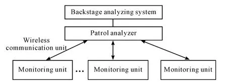
Figure 1.Structure of cable temperature monitoring system
3.2.Design of function module
From the Figure 1,it can be seen that the system is divided into three layers from bottom to top,and it is respectively the monitoring unit,patrol analyzer and backstage analysis system.The following is the illustration of design.
3.2.1.Monitoring unit
The terminal device installs at transition joint of each cable,and it is used for measuring and uploading measuring data.By means of wireless data transmission,the measured signal of terminal device output can be transmitted into data collection unit which is close-by the cable joint.The terminal device is the important constituent part in the system,and it is mainly in charge of sampling and storing the temperature data of setting time for cable joint.It makes communicate with patrol analyzer by wireless mode.In order to realize the low energy consumption,it takes battery to supply for the system.The low energy consumption can be solved from two respects,in which,one is to select low energy consumption device,and the other is to realize lots of working state such as transmitting,receiving,collecting data and sleep state etc.Through the management unit of electrical source,the microcomputer can control the working state of whole system.For example,it can ensure that the most time is in a certain condition of sleep state,and only the low frequency clock works in microprocessor.According to sampling interval of software setting,the system can start the temperature sensing unit to conduct temperature collecting and A/ D conversion,and make the got data store into the external storage unit.The radio communication unit takes very low duty cycle time to work,and when it only received the activated Signal sent by patrol analyzer and determined to be itself ID,and then according to the command demand,the temperature data is uploaded to patrol analyzer,in which the corresponding temperature data is taken from external storage unit of microprocessor.The hardware structure of terminal device is shown in Figure 2.
The thermometer used the 1-wire digital thermometer DS18B20 made by Maxim cooperation to be as the temperature sensor unit.The measuring range is from-55℃ to 125℃,and the accuracy is±0.15℃ range when from -10℃ to 85℃.The microprocessor adopts MSP430F149 chip produced by TI cooperation.Under the operation condition of the voltage range being from 1.8 to 3.6V and clock frequency being as 1 MHz,the consumption current is from 0.1 mA to 400 mA.The wireless transceiver unit adopts nRF2401 chip produced by NORDIC.The integrated wireless transceiver chip of nRF2401 works over 2.4 GHz free frequency channel,it adopts the FSK modulation that is strong in capacity of anti-jamming.
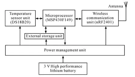
Figure 2.Structure of terminal hardware device
The software of the device adopts real time multi-tasking operation system[4],and it is developed by Tiny OS(TOS)referenced in smart dust technology.Based on the above,it also extended four application modules of timing temperature collecting,wake-up signal monitoring,data uploading and monitoring of human-computer interaction signal.The software structure of terminal device is shown in Figure 3.
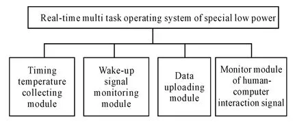
Figure 3.Structure of terminal device software
3.2.2.Patrol analyzer
The Portable cable joint temperature patrol analyzer is used for collecting temperature data of each cable joint in field by inspection personnel,and the patrol analyzer has two sorts of manual and automatic work mode.In the auto mode,as long as the terminal device comes into the signal coverage area,and then the signal can automatically be connected to terminal device.It can also select the manual work mode,and contrapuntally obtain the data information of some terminal devices.In addition,the analyzer has simple fault analysis ability,and through the a-nalysis processing of historical temperature data for a cable joint it can find out the alarm message in time for possible fault.The patrol analyzer consists of four units such as data reception,data processing,display device and USB interface as well as battery etc.and the hardware structure of patrol analyzer is shown in Figure 4.

Figure 4.Structure of patrol analyzer hardware
3.2.3.Backstage analysis system
The backstage analysis system is used for realizing the fault analysis and diagnosis of cable joint.The PC workstation makes the obtained data from patrol analyzer store into data base,and establishes historical records.According to the change of each cable joint temperature,the software of cable joint data management and fault analysis diagnosis can effectively analyze the situation of cable joint work.The analysis content includes the over temperature analysis,trend analysis of temperature rise,temperature gradient analysis and automatic temperature compensation etc,and it can make up the processing of alarm,comparison and historical record etc so as to ensure making early warning before the cable accident.
4.Realization of system and its application analysis
According to the above design,it is easy to realize the patrol inspection system.The system transmits the measure data by means of wireless communication mode,and it can be independent of each other among single terminal devices,and it is small in bulk,convenient in installation.It is also easy to make the enclosure design satisfy the characteristic such as explosion-proof,moisture protection and strong antijamming capability etc so as to meet the environment demand for bad underground work status.The distributed system can adapt to the change of power line,and the temperature monitoring is suitable for application of large-scale underground cable network.It is easy to use that the line inspection personnel by inspection instrument can conveniently get cable joint temperature,and at same time it can fast judge that the running state of cable line is normal or not,analyze the probably potential failure points,and give early warning signals synchronously.The experiment demonstrated that it is low in maintenance cost.The patrol inspection system is convenient to establish the link with terminal device,and the time required is less than 50 ms.The signal coverage radius of maximum power for each terminal device can reach to 50 m.
5.Conclusion
The above explored system overcomes the puzzles of similar systems such as being difficult to laying and maintenance in line,high cost and so on,and through insulation fault analysis of electric power cable,it can effectively avoid the cable fire disaster.The experiment demonstrated that the explored patrol inspection system of cable fault is feasible and reasonable.
[1] WANG Kun-ming,YANG Li-ming,RAO Wen-bin.A-nalysis of Failure of Moulding Joint of 110kV XLPE Power Cable[J].High Voltage Engineering,1993,19(1): 38-40.
[2] CHENG Yong-hong,XIE Heng,YI Li-dong.Study on the On-line Detecting Technique for Power Cable and Terminal Based on Heat Effect[J].High Voltage Engineering,1999,25(3):4-46.
[3] WANG Zhen-hao,XIN Ye-chun,DU Chang-jun,et al.On-line monitoring systems for power cable junctions in city zone[J].Power System Protection and Control,2009,37(2):69-72.
[4] REN Yan,LIANG Ming,HE Ying-ping,et al.Design of electrical load control system based on Wireless communication technology[J].ElectrotechnicalJournal,2004(10):26-28.
基于无线通信的地下电缆接头故障巡检系统*
游晓畅†1,李 雷2
1重庆工业职业技术学院机械工程学院,重庆401120;
2重庆大学自动化学院,重庆 400044
电缆接头温度是反映电网运行状态的重要参数。针对地下电缆接头故障难以检测的问题,探讨了一种基于无线通信的地下电缆接头故障巡检系统。分析了产生接头故障隐患的机理,设计了前端检测与后台分析系统及其相应的功能模块,利用无线通信方式实现了对地下电缆接头故障的巡检。测试数据显示:该系统可在大范围内实现巡检覆盖,便于计算机联网使用。实验结果表明:系统设计是可行和有效的。
电缆接头;地下电缆故障;无线通讯;巡检系统
TP273
10.3969/j.issn.1001-3881.2014.06.024
2013-11-25
猜你喜欢
杂志排行

机床与液压的其它文章
- Flow field CFD analysis of axial flow blood pump*
- Cam profile optimization design of variable cycle reciprocating piston engine*
- Control system design of automatic down-filling machine based on ARM7TDMI*
- Analysis of the characteristics and frequency for the annular water-air self-excited oscillation jet pump*