Optimization of process parameters of the activated tungsten inert gas welding for aspect ratio of UNS S32205 duplex stainless steel welds
2014-02-14MAGUDEESWARANSreehriNAIRLSUNDARHARIKANNAN
G.MAGUDEESWARAN*,Sreehri R.NAIRL.SUNDAR,N.HARIKANNAN
aDepartment of Mechanical Engineering,PSNA College of Engineering and Technology,Dindigul 624 622,Tamilnadu,India
bAdor Welding Limited,Melakottaiyur,Via-Vandalur,Chennai 600 048,Tamilnadu,India
Optimization of process parameters of the activated tungsten inert gas welding for aspect ratio of UNS S32205 duplex stainless steel welds
G.MAGUDEESWARANa,*,Sreehari R.NAIRa,L.SUNDARb,N.HARIKANNANa
aDepartment of Mechanical Engineering,PSNA College of Engineering and Technology,Dindigul 624 622,Tamilnadu,India
bAdor Welding Limited,Melakottaiyur,Via-Vandalur,Chennai 600 048,Tamilnadu,India
The activated TIG(ATIG)welding process mainly focuses on increasing the depth of penetration and the reduction in the width of weld bead has not been paid much attention.The shape of a weld in terms of its width-to-depth ratio known as aspect ratio has a marked infuence on its solidifcation cracking tendency.The major infuencing ATIG welding parameters,such as electrode gap,travel speed,current and voltage,that aid in controlling the aspect ratio of DSS joints,must be optimized to obtain desirable aspect ratio for DSS joints.Hence in this study,the above parameters of ATIG welding for aspect ratio of ASTM/UNS S32205 DSS welds are optimized by using Taguchi orthogonal array(OA) experimental design and other statistical tools such as Analysis of Variance(ANOVA)and Pooled ANOVA techniques.The optimum process parameters are found to be 1 mm electrode gap,130 mm/min travel speed,140 A current and 12 V voltage.The aspect ratio and the ferrite content for the DSS joints fabricated using the optimized ATIG parameters are found to be well within the acceptable range and there is no macroscopically evident solidifcation cracking.
Duplex stainless steel;ATIG welding;Aspect ratio;Taguchi design;Ferrite number;Solidifcation cracking
1.Introduction
Duplex stainless steel(DSS)typically comprises the microstructures consisting of approximately equal proportions of body-centered cubic ferrite and face-centered cubic austenite. These two phases possess varying affnities for alloying elements in duplex stainless steels[1-3].Duplex stainless steel is a common structural material used in the oil and gas industries,and has special applications in chemical,wastewater treatment and marine engineering felds as well.Strength of DSS is higher than that of the single-phase austenitic stainless steel.DSS are far better than many single-phase austenitic or ferritic stainless steels in terms of resistance to localized corrosion as well as stress corrosion cracking(SCC)[4-6]. DSS can be used in defence applications instead of conventionally used Austenitic stainless steel for the fabrication of water bowsers for carrying portable fresh drinking water to military operational areas where good quality of drinking water is not available and needed.The use of DSS for fabrication of water bowsers in military applications will be very much useful because it will increase the payload capacity of the water bowsers.A major concern for duplex stainless steel is that welding can degrade the strength and corrosion resistance of the microstructures by producing unbalanced ferrite/ austenite content in the weld metal.The phase balance of the weld metal is critical to maintain the original chemical and physical properties of duplex stainless steel.Therefore,thetechniques that control the ferrite/austenite content of the weld metal are very important[7].In the heat-affected zone(HAZ), the phase ratio is strongly dependent on the weld thermal cycle[8,9].
Welding process,fller metal additions,shielding gas and heat input are important factors that contribute to establish the equal proportion of austenite-ferrite phase ratio(1:1)in the weld metal region.However,in practice it is not possible to establish 1:1 austenite-to-ferrite ratio in all the zones of the welded joints.The advisable and desired ferrite content in the weld joint is 30-55%for better performance of the duplex stainless steel to serve the purpose for which it is intended. Welding procedures should be designed to produce this same structure in the weld metal and heat-affected zones.Most of the conventional welding processes,such as submerged arc welding(SAW),shielded metal arc welding(SMAW)and tungsten inert gas(TIG)welding,can be used for welding DSS[5,8,10].TIG welding process is one of the most popular technologies for welding thin materials in manufacturing industries because it produces high quality welds.However, compared with the metal inert gas welding process,the TIG welding has poor joint penetration when thick materials are welded in a single pass.Generally,the single pass TIG welding with argon as shielding gas is limited to a 3 mm depth for the butt-joint of stainless steels.Therefore,it is necessary to improve the penetration capability and manufacturing productivity of TIG welding[11-14].One of the most notable techniques is to use activating fux with TIG welding.To make an activating fux,powder ingredients such as oxides,chlorides,and fuorides are typically added to acetone or ethanol solvent to produce a paint-like constituent. Before welding,a thin layer of the fux was brushed on to the surface of the joint to be welded[15-19].The Paton Welding Institute of Kiev(Ukraine)was the frst to develop this process[19],called the activated TIG welding(ATIG)process. Activated TIG improves upon conventional GTAW,by increasing the single pass joining thickness from 6 to 10 mm for stainless steel[7,20].The activated TIG welding process typically results in a 200-300%increase in penetration capability,thereby reducing weld time and costs for manufacturers[21-24].
The activated TIG(ATIG)process mainly focuses on increasing the depth of penetration and the reduction in the width of weld bead has not been paid much attention.Higher width of the weld bead results in greater heat affected zone which is not desirable for any welded joint.A controlled weld thermal cycle of activated TIG(ATIG)welding process that gives deeper penetration and smaller width is very much appreciated for DSS joints.Therefore,it is essential to analyze both depth of penetration,D,and width of the weld bead,W.The shape of a weld in terms of its width-to-depth ratio known as aspect ratio has a marked infuence on its solidifcation cracking tendency.Therefore,it is necessary to explore the most infuencing ATIG welding process parameters that aid in controlling the aspect ratio of DSS joints and must be optimized to obtain desirable aspect ratio for DSS joints for structural integrity of the joints by using a systematic process optimization techniques.Taguchi method was developed as a process optimization technique by Genichi Taguchi.This approach provides the design engineers with a systematic and effcient method for determining nearoptimum design parameters for performance and cost. Additionally,the optimum working conditions determined from the laboratory work can be reproduced in the real production environment[25,26].Various steps of Taguchi method are shown in Fig.1.Hence,in this study,an attempt has been made to optimize the above parameters of ATIG welding for aspect ratio of ASTM/UNS S32205 DSS welds using Taguchi orthogonal array(OA)experimental design and other statistical tools such as Analysis of Variance(ANOVA) and Pooled ANOVA techniques[27].This investigation assumes signifcance,as no systematic study has been reported so far,to analyze the infuence of process parameters of ATIG welding to obtain desirable aspect ratio(ASR)of DSS joints.
2.Experimental work
2.1.Base metal
The base metal used in this study is a duplex stainless steel (ASTM/UNS:S32205),which chemical composition is presented in Table 1.The microstructural feature of the base metal exhibits a dulplex structure with embedded grains of austenite(white)and ferrite(brown),as shown in Fig.2.
2.2.Process parameters and their levels
The independently controllable predominant process parameters of ATIG welding that control aspect ratio of DSS joints are identifed as electrode gap,travel speed,current andvoltage.The ranges of the parameters are decided based on the several experimental trials and are listed in Table 2.
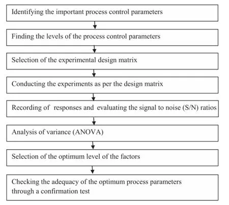
Fig.1.Various steps of Taguchi method.

Table 1Chemical composition(wt%)of base metal.
2.3.Taguchi design of experiments(DOE)
Taguchi method is a systematic application of design and analysis of experiments for the purpose of designing and improving product quality.The Taguchi method uses a special OA to study all the designed factors with a minimum of experiments.Orthogonality means that each factor is independently evaluated and the effect of one factor does not interfere with the estimation of the infuence of another factor[28,29]. Table 2 shows the key four ATIG welding process parameters investigated at the three experimental levels.In the next step,a matrix was designed with the appropriate OAs for the selected parameters and their levels.
The OA experimental design method was chosen to determine an experimental plan,L9(34)(Table 3),because it is the most suitable for the conditions being investigated;for the four parameters,each has three values[30].The L9(34),which indicates 9 experimental trials,is one of the standard orthogonal experimental plans of Taguchi.The order of the experiments was obtained by inserting the parameters into the columns of OA,L9(34),chosen as the experimental plan listed in Table 3,but the order of experiments was made randomly to avoid the noise sources which had not been considered initially and took place during an experiment and affected the results in a negative way.
Taguchi method recommends the signal-to-noise(S/N) ratio,which is a performance characteristic,instead of the average value.Optimum conditions were determined using the S/N ratio from experimental results[27].There are three S/N ratios of common interest for the optimization of static problem,i.e.,the higher the better(HB),the lower the better(LB), and the nominal the better(NB).The larger S/N ratio represents to better performance characteristic.
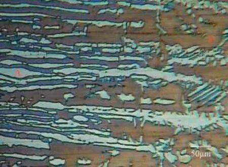
Fig.2.Microstructure of base metal(A:Austenite;F:Ferrite).
The mean S/N ratio at each level for various factors was calculated.Moreover,the optimal level,that is the largest S/N ratio among all the levels of the factors,can be determined.A statistical analysis of variance(ANOVA)was also performed to indicate which process parameters are statistically signifcant;the optimal combination of the process parameters can then be reproduced.In order to validate the methodology,the confrmation experiments must be performed using optimal process parameters to verify the predicted results.If the predicted results are confrmed,the suggested optimum working conditions should be adopted[31].
2.4.Conducting the experiments as per design matrix
Rolled plate made from 6 mm thick base metal was sliced into small required plates(100 mm×150 mm)by abrasive cutters and then they were ground.Square butt joint confguration,as shown in Fig.3,is prepared to fabricate the joints by tungsten inert gas(TIG)welding using activated fux without addition of any fller material(autogenous welding).In this study,the autogenous welding was carried out using a typical branded activated fux:(Ador A-TIG Flux 1).The branded activated fux is a penetration enhancing activating fux.It is made of different kinds of inorganic oxide materials which change the surface activity and primarily reduces the heat energy required for penetration.Surface active elements in the weld pool ensure that the joint penetration increases drastically.Arc is constricted by the fux coated on the surface of the plate,and the concentrated arc energy increases weld penetration.The initial joint confguration was obtained by securing the plates in position using tack welding.The direction of welding was normal to the rolling direction.All necessary care was taken to avoid joint distortion,and the joints were made after the plates were clamped in a welding fxture.The welding was carried out using a TIG welding machine(Model:HF 3000 AD,Make:Ador Welding Limited).The electrode gap and the travel speed were controlled and maintained by using an automatic torch traveler (Model:E-cutpro(Panther NM),Make:Ador Welding Limited).The welding was carried out by using 3.2 mm nonconsumable tungsten electrode with high-purity argon (99.99%)with a fow rate of 18 L per minute.The welding was carried out in sequential order with the parameters shown in Table 3.
2.5.Recording of responses
Macro examination was carried out using a stereo microscope(Model:5737312,Make:LEICA)incorporated with an image analyzing software.The specimens for macro examination were sectioned according to the required sizes and werepolished using different grades of emery papers.Final polishing was done using the diamond compound(1μm particle size)in the disc polishing machine.The specimens were etched with 10%NaOH at 2-3 V and 6-10 V by using electrolytic etching method,respectively.From the obtained macrostructure depth of penetration,D,and the width of weld bead,W,were measured for all the joints,as shown in Fig.4. The aspect ratio(ASR)was calculated for all the joints and are listed in Table 4.D and W(Fig.5)were measured and the aspect ratio(ASR)was also calculated for the joint fabricated using the optimized parameters and is listed in Table 8. Further,the ferrite content(FN:ferrite number)was measured in the weld zone for the above joint by using a ferritescope (Model:MP 30 E,Make:Fischer)to check the austenite-ferrite balance and the average value is tabulated in Table 8.

Table 2Process Parameters and their levels.
2.6.Evaluating the signal-to-noise(S/N)ratios
In this study,an L9(34)OAwith 4 columns and 9 rows was used.This array can handle three-level process parameters. Nine experiments were necessary to study the welding parameters using the L9(34)OA.In order to evaluate the infuence of each selected factor on the responses,the S/N ratios for each control factor was calculated.
In the Taguchi method,the terms‘‘signal’’and‘‘noise’’represent the desirable and undesirable values for the output characteristic,respectively.Taguchi method uses the S/N ratio to measure the quality characteristic deviating from the desired value.The S/N ratios are different according to the type of characteristic.
Suitable S/N ratio must be chosen using previous knowledge,expertise,and understanding of the process.When the target is fxed and there is a trivial or absent signal factor (static design),it is possible to choose the S/N ratio,depending on the goal of the design.
As mentioned above,there are three categories of quality characteristics,i.e.,HB,LB,and NB.The performance statistics were chosen as the optimization criterion.In this study, aspect ratio(ASR)is treated as a characteristic value.Since the aspect ratio is intended to be maximized,they were both used for‘‘HB’’situations,and evaluated using the following equation[27,31].

!
where S/N,defned as the signal-to-noise ratio(S/N unit:dB); n is the number of repetitions for an experimental combination;and Yiis a performance value of the ith experiment.Table 4 shows the experimental results for aspect ratio and the corresponding S/N ratios calculated from Eq.(1).The total mean S/N ratio for aspect ratio is ηm=(total S/N ratio)/ (number of experimental runs)=2.67 dB.Moreover,the calculated heat inputs for each series of experiments are also listed in Table 4.
It is then possible to separate out the effect of each parameter at the different levels since the experimental design is orthogonal[32].In fact,the average performance(mean S/N ratio)of a factor at certain level is the infuence of the factor at this level on the mean response of the experiments.In the case of aspect ratio,in order to compute the average performance of the factor B at Level 1(denoted as B1),the results for trialsincluding factor B1are added and then divided by the number of such trials:

Table 3Experimental Layout using L9(34)orthogonal array(OA)with coded and original level values.
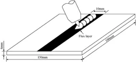
Fig.3.Joint confguration.

The mean S/N ratio for each level of the other parameters can be calculated in the same way.The mean S/N ratio for each level of the parameters is summarized,and the S/N response table for aspect ratio is listed in Table 5.
Rank 1 in Table 5 shows that electrode gap has more signifcant effect on the aspect ratio,followed by current,voltage and travel speed.Also,it is inferred that travel speed does not have much infuence on the aspect ratio.However,the levels of the parameters have different infuences on the aspect ratio.
2.7.Analysis of variance(ANOVA)
The knowledge of the contribution of individual factors is critically important for the control of the fnal response.The ANOVA is a common statistical technique to determine the percent contribution of each factor for the experimental results [33].It is used to calculate the parameters known as sum of squares(SS),corrected sum of squares(SS'),degree of freedom(D),variance(V),and percentage of the contribution of each factor(P).Since the procedure of ANOVA is very complicated and employs a considerable number of statistical formulae,only a brief description is given as follows[27,34]:

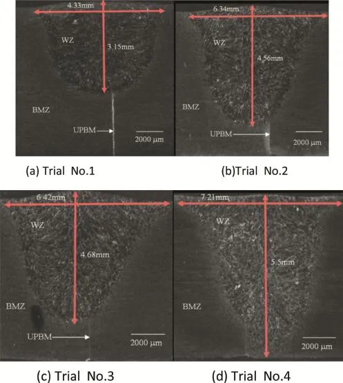
Fig.4 Macrostructure of the joints revealing the width of the weld bead and depth of penetration for DSS Joints as per L9(34)orthogonal array illustrated in Table 3 (WZ:weld zone;BMZ:base metal zone;UPBM:unpenetrated base metal).
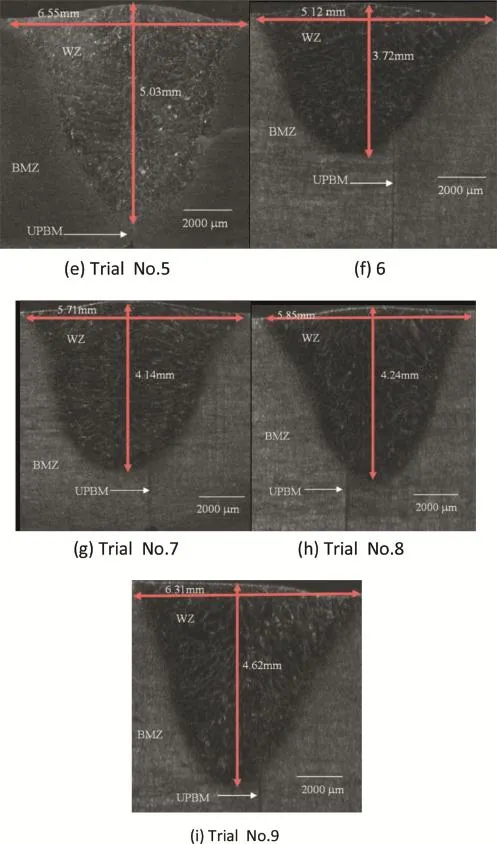
Fig.4.(continued).
where SSTis the total sum of squares;m is the total number of the experiments;and ηiis the S/N ratio at the ith test.

where SSprepresents the sum of squares from the tested factors;p is the one of the tested factors,j is the level number of this specifc factor p;t is the repetition of each level of the factor p;and Sηjis the sum of S/N ratio involving this factor and the level j.

Table 4Experimental results and corresponding S/N ratios and heat inputs.

where Vpis the variance from the tested factors;and Dpis the degree of freedom for each factor.
Basically,the degrees of freedom(DOF)for OA should be greater than or at least equal to those for the parameters[27]. For example,a fve-level design parameter counts for four-DOF.In this study,the experimental DOF is 8(number of trails minus one);while parameters-DOF is 2(number of parameter levels minus one).

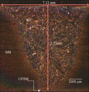
Fig.5.Macrostructure of the joints revealing the width of the weld bead and depth of penetration for DSS Joints fabricated using the optimized process parameters as illustrated in Table 8(WZ:weld zone;BMZ:base metal zone; UPBM:unpenetrated base metal).

where Ppis the percentage of the contribution to the total variation of each individual factor.
The ANOVA results are presented in Table 6.As seen in Table 6,the electrode gap is the most signifcant factor on aspect ratio with contribution of 53.99%,followed by current with contribution of 27.62%.The voltage and travel speed are insignifcantwith contribution of14.55% and 3.82%, respectively.
2.8.Pooled ANOVA
In the ANOVA analysis,if the contribution percent is high, the contribution of the factors to that particular response is more.Likewise,the smaller the contribution percent is,the lower the contribution of the factors on the measured response is.Therefore,another analysis is conducted by pooling the insignifcant factors to error(see Table 7).The process of disregarding an individual factorcontribution and then adjusting the contribution of the other factor is known as pooling[34].The results of ANOVA after pooling for aspect ratio are presented in Table 7.Pooled ANOVA values reveal that the electrode gap(44.80%)is a signifcant factor for the aspect ratio in the ATIG welding process.
Once the optimal level of the design parameters is selected, the fnal step is to predict and verify the improvement of the quality characteristic using the optimal level of the design parameters[32,35].The S/N ratio predicted using the optimal level of the design parameters can be calculated[32]:

where ηmis the total mean S/N ratio;ηiis the mean S/N ratio at the optimal level;and n is the number of the main designparameters that affect the quality characteristic.The S/N ratio predicted using the optimal ATIG parameters for aspect ratio can then be obtained and the corresponding aspect ratio can also be calculated using Eq.(1).

Table 5S/N response table.

Table 6Results of the ANOVA.
Table 8 shows the comparison of the predicted aspect ratio with the experimental results using the optimal conditions. There is good agreement between the predicted and experimental aspect ratios being observed.However,the optimized parameters obtained for welding ASTM/UNS S32205 DSS in this study should be justifed for its use in real-time engineering application and are illustrated below.
3.Discussion
Solidifcation cracking generally occurs slightly above the melting temperature of the lowest melting constituent,which is sometimes referred to as the effective solidus temperature [36].At this point in the solidifcation process of weld,the adjacent dendrites impinge upon each other to form the solidifed bridges,which are surrounded by the regions containing lower-melting interdendritic liquid.These solid bridges are subject to the greatest shrinkage-induced strain as the surrounding material cools.A threshold amount of either lowmelting liquid or strain may cause the fracture of these solid bridges and the subsequent formation of a weld hot crack [37,38].Based on the correlation between cracking susceptibility and solidifcation behaviour developed for the austenitic stainless steels,the susceptibility of the duplex alloys to hot cracking would be expected to be low[39].The solidifcation cracking is generally produced during the fnal stages of solidifcation and very much depends on the geometrical factors, such as width of weld bead,W,and depth of penetration,D.W and D are two major factors in achieving a good weld and depend on the welding procedure to a large extent.The shape of a weld in terms of width-to-depth ratio known as aspect ratio(ASR)has a marked infuence on its solidifcation cracking tendency,which can be minimized by ensuring that ASR is between 1 and 1.4 and is illustrated in Fig.6[40].ASR is a predominant factor that affects solidifcation cracking in structural steel joints and is applicable to DSS joints also.In this study,ASR is found to be 1.24(W:7.12 mm;D:5.72 mm) for the joint fabricated using optimized process parameters: travel speed(130 mm/min),current(140 A),voltage(12 V) and electrode gap(1 mm).There is no evidence solidifcation cracking macroscopically and is evident from the macrograph for the above joint(Fig.5).
Max heat input allowed for this grade is 2.5 kJ/mm.For TIG welding,it is desirable to have the heat input from 0.75 to1.5 kJ/mm.The optimized process parameters of activated GTA welding process in this study yielded a heat input of 0.778 kJ/mm which is within the recommended levels.The goal to weld any duplex stainless steel is to obtain fusion and heat-affected zones having the excellent corrosion resistance of the base metal and suffciently high impact toughness for application.ASTM/UNS S32205 grade base metal has an annealed structure with the equal proportion of austeniteferrite phases and is virtually free of intermetallic phases. Welding procedures should be designed to produce this same structure in the weld metal and the heat-affected zones.The weld thermal cycle,fller metal and protection atmosphere, can control this structure.Near the fusion temperature,the structure of duplex stainless steels is entirely ferritic.The desired 30-55%ferrite can be achieved only if the cooling rate is slow enough to allow austenite to re-form as the weld cools.If the cooling rate is too slow,however,embrittling intermetallic phases may form in spite of the presence of the optimum ferrite content.Extremely low heat input followed by rapid cooling may produce a predominant ferritic heat-affected zone with reduced toughness and corrosion resistance[41,42]. In this study,the average ferrite number(FN)in the weld zone for the joints fabricated using the optimized process parameters is 71.62,and the ferrite content is approximately 50.674% which is well within the acceptable range.Hence,the optimized process parameters are justifed for welding ASTM/ UNS S32205 grade DSS by ATIG welding process.

Table 7Pooled ANOVA for aspect ratio.

Table 8Evaluation of the predicted aspect ratio with the experimental results of the confrmation experiment using optimal condition.
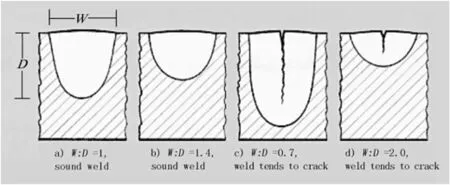
Fig.6.Effect of weld shape on solidifcation cracking tendency[40].
4.Conclusions
In this study,the ATIG welding process parameters were optimized for ASTM/UNS S32205 DSS joints to obtain desirable aspect ratio,and the results were analysed in detail. We can draw the following conclusions.
1)The electrode gap is the predominant factor that affects the aspect ratio of DSS welds fabricated using ATIG welding process.
2)The optimum welding parameters are found to be electrode gap of 1 mm,travel speed of 130 mm/min,current of 140 A,and voltage of 12 V.
3)The confrmation experimental results for aspect ratio is in good agreement with the data analyzed by the Taguchi method
1999年,爱彼进入中国市场。在精简的通路策略下,据统计,到2018年6月,爱彼目前在中国大陆仅设有6家专卖店。在这种情况下,如何利用合适的线上渠道,广泛但精准的触达更多中国新兴中高产阶级人群,是爱彼的第一层需求。
4)The aspect ratio is found to be 1.24 for the joints fabricated using the optimized process parameters and is well within the acceptable range to avoid solidifcation cracking.
5)Average ferrite number(FN)in the weld zone for the joints fabricated using the optimized process parameters is 71.62,and the ferrite content is approximately 50.674% which is well within the acceptable range.
6)There is no evident solidifcation cracking macroscopically for the DSS joints fabricated using optimized ATIG welding process parameters.
7)DSS can be used for fabrication of water bowsers for carrying portable fresh drinking water to military operational areas where good quality of drinking water is not available.
Acknowledgement
The authors are thankful to M/s Outokumpu Stainless Steel AB,Sweden for providing duplex stainless steel base metal and M/s Ador Welding Limited,Chennai,India for providing the fabrication facility and consumables for this investigation.
[1]Davis JR.ASM specialty handbook-stainless steels.Materials Park,OH: ASM International;1996,ISBN 0-87170-503-6.
[2]Farnoush H,Momeni A,Dehghani K,Aghazadeh Mohandesi J, Keshmiri H.Hot deformation characteristics of 2205 duplex stainless steelbased on thebehaviorofconstituentphases.MaterDes 2010;31(1):220-6.
[3]Tavares SSM,Terra VF,Parada JM,Cindra Fonseca MP.Infuence of the microstructure on the toughness of a duplex stainless steel UNS S31803. J Mater Sci 2005;40(1):145-54.
[4]Eriksson H,Bernhardsson S.The applicability of duplex stainless steels in sour environments.Corrosion 1991;47(9):719-27.
[5]Muthupandi V,Bala Srinivasan P,Seshadri SK.Effect of Weld metal chemistry and heat input on the structure and properties of duplex stainless steel Weld.Mater Sci Eng A 2003;358(1-2):9-16.
[6]Chern Tsann-Shyi,Tseng Kuang-Hung,Tsai Hsien-Lung.Study of the characteristics of duplex stainless steel activated tungsten inert gas welds. Mater Des 2011;32(1):255-63.
[7]Hertzman Staffan,Ferreira Paulo J,Brolund Bengt.An experimental and theoretical study of heat-affected zone austenite reformation in three duplex stainless steels.Mettallurg Mater Trans A 1997;28A:277-85.
[8]Iris Alvarez-Armas duplex stainless steels:brief history and some recent alloys recent patents on mechanical engineering1;2008.p.51-7.
[9]Saeid T,Abdollah-Zadeh A,Assadi H,Ghaini FM.Effect of friction stir welding speed on the microstructure and mechanical properties of a duplex stainless steel.Mater Sci Eng A 2008;496(1-2):262-8.
[10]Reddy GM,Rao KS.Microstructure and mechanical properties of similar and dissimilar stainless steel electron beam and friction welds.Int J Adv Manuf Technol 2009;45(9-10):875-88.
[11]Parmar RS.Welding engineering and technology.2nd ed.New Delhi: Khanna Publishers;2003.
[12]Huang HY,Shyu SW,Tseng KH,Chou CP.Evaluation of TIG fux welding on the characteristics of stainless steel.Sci Technol Weld Join 2005;10(5):566-73.
[13]Shyu SW,Huang HY,Tseng KH,Chou CP.Study of the performance of stainless steel A-TIG welds.J Mater Eng Perform 2008;17(2):197-201. [14]Fujii H,Sato T,Lu SP,Nogi K.Development of an advanced A-TIG (AA-TIG)welding method by control of Marangoni convection.Mater Sci Eng A 2008;495(1-2):296-303.
[15]Huang HY,Shyu SW,Tseng KH,Chou CP.Effects of the process parameters on austenitic stainless steel by TIG-fux welding.J Mater Sci Technol 2006;22(3):367-74.
[16]Lu SP,Li DZ,Fujii H,Nogi K.Time dependant weld shape in Ar-O2 shielded stationary GTA welding. J Mater Sci Technol 2007;23(5):650-4.
[17]Tseng Kuang-Hung,Hsu Chih-Yu.Performance of activated TIG process in austenitic stainless steel welds.J Mat Proc Tech 2011;211(3):503-12.
[18]Chern TS,Tseng KH,Tsai HL.Study of the characteristics of duplex stainless steelactivated tungsten inertgaswelds.MaterDes 2011;32(1):255-63.
[19]Gurevich SM,Zamkov VN,Kushnirenko NA.Improving the penetration of titanium alloys when they are welded by argon tungsten arc process. Avtom Svar 1965;9:1-4.
[20]Leconte S,Paillard P,Chapelle P,Henrion G,Saindrenan J.Effect of oxide fuxes on activation mechanisms of tungsten inert gas process.Sci Technol Weld Join 2006;11(4):389-97.
[21]Marya M,Edwards GR.Chloride contributions in fux-assisted GTA welding of magnesium alloys.Weld J 2002;81(12):291s-8s.
[22]Heiple CR,Roper JR.Effect of selenium on GTAW fusion zone geometry.Weld J 1981;60(8):143s-5s.
[23]Heiple CR,Roper JR.Mechanism for minor element effect on GTA fusion zone geometry.Weld J 1982;61(4):97s-102s.
[24]Lucas W,Howse D.Activating fux-increasing the performance and productivity of the TIG and plasma processes.Weld Metal Fabr 1996;64(1):11-7.
[25]Ozbay E,Oztas A,Baykasoglu A,Ozbebek H.Investigating mix proportions of high strength self compacting concrete by using Taguchi method.Constr Build Mater 2009;23(2):694-702.
[26]Turkmen I,Gul R,Celik C,Demirboga R.Determination by Taguchi method of optimum conditions for mechanical properties of high strength concrete with admixtures of silica fume and blast furnace slag.Civ Eng Environ Syst 2003;20(2):105-18.
[27]Yousefeh M,Shamanian M,Saatchi A.Optimization of the pulsed current gas tungsten arc welding(PCGTAW)parameters for corrosion resistance of super duplex stainless steel(UNS S32760)welds using the Taguchi method.J Alloys Compd 2011;509(3):782-8.
[28]Ross P,Taguchi J.Techniques for quality engineering.McGraw-Hill International Editions,New York,give the press;1988.
[29]Wang Y,Northwood DO.Optimization of the polypyrrole-coating parameters for proton exchange membrane fuel cell bipolar plates using the Taguchi method.J Power Sources 2008;185(1):226-32.
[30]Madhav Phadke S.Quality engineering using robust design.Upper Saddle River,NJ:Prentice Hall;1989.
[31]BerilGonder Z,Kaya Y,Vergili I,Barlas H.Optimization of fltration conditions for CIP wastewater treatment by nanofltration process using Taguchi approach.Sep Purif Technol 2010;70(3):265-73.
[32]Yang WH,Tarng YS.Design optimization of cutting parameters for turning operations based on the Taguchi method.J Mater Process Technol 1998;84(1-3):122-9.
[33]Yang k,Teo EC,Fuss FK.Application of Taguchi method in optimization of cervical ring cage.J Biomech 2007;40(14):3251-6.
[34]Ma Y,Hu H,Northwood D,Nie X.Optimization of the electrolytic plasma oxidation processes for corrosion protection of magnesium alloy AM50 using the Taguchimethod.J Mater Process Technol 2007;182(1-3):58-64.
[35]Kim KD,Han DN,Kim HT.Optimization of experimental conditions based on the Taguchi robust design for the formation of nano-sized silver particles by chemical reduction method. Chem Eng J 2004;104(1-3):55-61.
[36]Savage VVF,Tundin CD,Aronson AH.Weld metal solidifcation mechanics.Weld J 1965;44(4):175s-81s.
[37]Savage WF,Nippes EF,Miller TVV.Microsegregation in 70Cu-30Ni weld metal.Weld J 1976;55(6):165s-73s.
[38]Borland JC.Hot cracking in welds.Brit Weld J 1960;7(9):558-9.
[39]Nelson DE,Baeslack III WA,Lippod JC.An investigation of Weld hot cracking in duplex stainless steels.Weld J 1987;66(8):214s-50s.
[40]Neville.Gregory,why do welds crack.TWI Bull March/April 1991:1-8.
[41]Outokumpu.How to weld type 2205 code plus two duplex Stainless steel, lack of basic info?www.outokumpu.com/stainless/na.
[42]Outokumpu.Welding handbook.1st ed.Finland:Outokumpu Oyi;2010.
Received 14 May 2014;revised 4 June 2014;accepted 5 June 2014Available online 25 July 2014
*Corresponding author.Tel.:+91 4512480543.
E-mail addresses:magudeeswaran@yahoo.com,gmagudeeswaran@gmail. com(G.MAGUDEESWARAN).
Peer review under responsibility of China Ordnance Society.
http://dx.doi.org/10.1016/j.dt.2014.06.006
2214-9147/Copyright©2014,China Ordnance Society.Production and hosting by Elsevier B.V.All rights reserved.
Copyright©2014,China Ordnance Society.Production and hosting by Elsevier B.V.All rights reserved.
猜你喜欢
杂志排行
Defence Technology的其它文章
- Investigation on the foaming behaviors of NC-based gun propellants
- Indirect robust control of agile missile via Theta-D technique
- Numerical simulation of base fow with hot base bleed for two jet models
- Analysis on the resistive force in penetration of a rigid projectile
- Numerical simulation of detonation of an explosive atmosphere of liquefed petroleum gas in a confned space
- Combined proportional navigation law for interception of high-speed targets
