Numerical simulation of base fow with hot base bleed for two jet models
2014-02-14WenjieYUYonggngYUBinNI
Wen-jie YU*,Yong-gng YUBin NI
aSchool of Energy and Power Engineering,Nanjing University of Science&Technology,Nanjing 210094,China
bNorth Information Control Group Ltd,Nanjing 211153,China
Numerical simulation of base fow with hot base bleed for two jet models
Wen-jie YUa,*,Yong-gang YUa,Bin NIb
aSchool of Energy and Power Engineering,Nanjing University of Science&Technology,Nanjing 210094,China
bNorth Information Control Group Ltd,Nanjing 211153,China
In order to improve the benefts of base bleed in base fow feld,the base fow with hot base bleed for two jet models is studied.Twodimensional axisymmetric Navier-Stokes equations are computed by using a fnite volume scheme.The base fow of a cylinder afterbody with base bleed is simulated.The simulation results are validated with the experimental data,and the experimental results are well reproduced. On this basis,the base fow felds with base bleed for a circular jet model and an annulus jet model are investigated by selecting the injection temperature from 830 K to 2200 K.The results show that the base pressure of the annular jet model is higher than that of the circular jet model with the changes of the injection parameter and the injection temperature.For the circular jet model,the hot gases are concentrated in the vicinity of the base.For the annular jet model,the bleed gases fow into the shear layer directly so that the hot gases are concentrated in the shear layer.The latter temperature distribution is better for the increase of base pressure.
Fluid mechanics;Base bleed;Base fow;Numerical simulation;Annulus jet
1.Introduction
Base drag on the projectile due to the reduced pressure on the base is a signifcant portion of the total drag in the supersonic regimes[1].Since the bleeding of hot gases from the base can signifcantly increase the base pressure,it became an important technique for reducing the base drag[2].Hot bleed gases contain a lot of energy.Previous studies have shown that the added mass of bleed gases contributes 20%of all for drag reduction,but the added energy of bleed gases contributes 80%of all for drag reduction[3].This shows that the injection temperature is a key to drag reduction.
Bowman et al.[4]experimentally studied the base pressure of the cylinder model in the case of different injection temperatures and different injection parameters.They found that the higher the temperature of bleed gases was,the higher the base pressure was.Even if the temperature of bleed gases reached 5070 K,the base pressure still increased.Ding et al. [3]experimentally studied the combustion of the partially premixed combustible gas in the base which could refect the effect of secondary combustion.They found that the drag reduction rate of base bleed with base burn was an order of magnitude higher than the drag reduction rate of cold base bleed.
Sahu et al.[5]simulated the base fow of a cylinder model with cold base bleed.They found that the base pressure frst increased and then decreased with the increase in injection parameter.Gibeling and Buggeln[6]numerically simulated the base combustion with a H2-CO combustion model which contains 10 components and 25 reactions,and investigated the tail fow feld of base bleed at low injection level(I=0.0022). Choi et al.[7]numerically simulated the full fow feld of the hybrid-propulsion projectile by considering the combustioncharacteristics of HTPB and AP(NH4ClO4).Chen et al.[8] computationally studied the impact of injection energy on the aerodynamic characteristics of base bleed projectiles. Shin et al.numerically simulated the tail fow feld of base bleed by using the large eddy simulation[9]and the detached eddy simulation[10],and studied the size and shape of the tail recirculation zone.
The temperature distribution in base fow feld affecting the base bleed has not been reported.In this paper,the simulation results were validated using the experimental data in Ref.[11]. Then the base fow felds with base bleed for a circular jet model and an annulus jet model were studied.By comparing the pressure and temperature distributions in the tail region between two models,the infuence of temperature distribution in base fow feld on the base bleed was analyzed.The mechanism of the drag reduction with base bleed was revealed.
2.Theory
Fig.1 shows the base fow with base bleed.Hot bleed gases fow along the cracks between the annular recirculation zone and the main recirculation zone,and then fow into the shear layer.Since the structure of shear layer changes because of the hot bleed gases,the separated streamline becomes straight, and the strength of recompressive shock is greatly weakened. Eventually the base pressure increases.If the annular recirculation zone can be weakened,and the hot bleed gases can fow into the shear layer more easily,the base pressure will further increase.
Fig.2 shows a simulation model of cylindrical afterbody. In Fig.2,x and y denote the axial coordinate and the radial coordinate,respectively;R denotes the radius of axisymmetric body;rj,rj1,and rj2denote the sizes of the bleed exit; Ma∞,p∞and T∞denote Mach number,pressure and temperature of the free stream,respectively;Tjdenotes the injection temperature;and I denotes the injection parameter which is defned as where˙mjis the mass fow rate;A is the base area;ρ∞and V∞denote the density and velocity of the free stream,respectively. The jet areas of two models are the same.Specifc parameters of the simulation are given in Table 1.

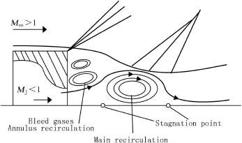
Fig.1.Schematic diagram of base fow with base bleed.
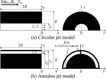
Fig.2.Schematic of base bleed model.
The annulus jet model is fxed by using four reinforced ribs. The infuence of reinforced rib on the base fow is ignored in simulation,and the geometry of fow feld is considered to be axisymmetric.
Since the geometry of fow feld is axisymmetric,the governing equations are two-dimensionalaxisymmetric Navier-Stokes equations.The coupled form of the fuid dynamics and turbulent transport equations can be summarized in a conservative vector form as follows
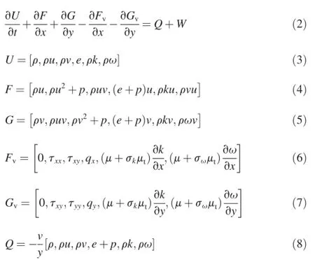

Table 1Simulation parameters.

where U is the conservative variable vector;F and G are the convective fux vectors;Fvand Gvare the diffusion fux vectors;W and Q are the turbulent source term and the axisymmetric source term,respectively;u and v are the velocities in axial direction and radial direction,respectively;τ,λ,μ and μtare viscous stress tensor,thermal conductivity,molecular and turbulent viscosity,respectively; k and ω are the kinetic energy and dissipation rate of turbulence,respectively;qxand qyare the heat fuxes;e is the total internal energy per unit volume;the turbulent sources Skand Swand the parameters σkand σware given in Ref.[12].
3.Numerical method
Simulation is conducted by using a fnite volume scheme. Convective term is dispersed by using the improved AUSM+ method containing Van Leer limiter[13].Diffusion term is dispersed by using the central difference method.Time term is dispersed by using the LU-SGS implicit time marching method[14].
Arc-length method is used to generate the grids[15].Fig.3 shows the grids of base region of the annular jet model.As shown in Fig.3,the far feld boundary is assigned a nonrefecting boundary condition,the wall boundary is assigned a no-slip adiabatic condition,the central axis boundary is assigned a symmetry condition,and the bleed exit boundary is directly given.
The frst y+is less than 2 on the wall.The three grids,of which the mesh numbers are 18,900,29,000 and 35,000, respectively,are used to test the grid independent of circular jet model.Fig.4 shows the axial velocity distributions on the central axis.When the mesh number of the grid is more than 29,000,the axial velocity distribution hardly changes with the increase in the mesh number of the grid.It can be considered that the fow feld of the base region is not affected by the grid when the mesh number of the grid is more than 29,000.So the grid of which the mesh number is 29,000 is used for the circular jet model.The grid of which the mesh number is 32,000 is selected for the annular jet model by using the same method.
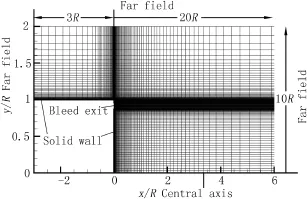
Fig.3.Grids of base region of annular jet model.
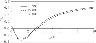
Fig.4.Axial velocity distributions on the central axis for circular jet model.
4.Results and discussion
Simulation results were validated using the experimental data in Ref.[11].Experimental model is a cylinder afterbody with base bleed.The bleed gases are cold,and the bleed jet is a circular jet.Simulation is conducted using the experimental conditions for validation.The specifc experimental conditions can be checked in Ref.[11].
The comparison of area-averaged base pressure at different injection levels is shown in Fig.5.Area average means to average in the area of the solid wall in the base.As shown in Fig.5,the simulation results reproduce the experimental data well in the trend.With the increase in the injection parameters, the base pressure frst increases,and then decreases.The comparison of base pressures at different radial positions is shown in Fig.6.The pressure distribution along the radial direction is straight,as shown in Fig.6.The simulation results agree with the experimental data well.
In order to investigate the infuence of the temperature distribution in base fow feld on the base bleed,the base pressures,tail temperature felds,tail recirculation zones and tail pressure felds of circular jet model and annulus jet model are compared,respectively.Fig.7 shows the comparison of the area-averaged base pressures at different injection temperatures.As shown in Fig.7,for the circular jet model,with the increase in the injection temperatures,the growth of base pressure becomes faster and faster,and the pressure peak appears earlier and earlier.For the annulus jet model,the base pressure always increases with the increase in the injectionparameters,and the pressure peak doesn't appear.With the increase in the injection temperatures,the base pressure becomes higher and higher for the annulus jet model.
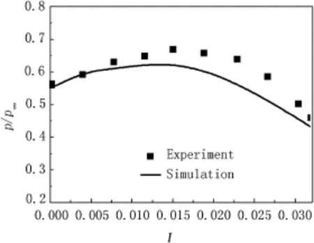
Fig.5.Area-averaged base pressures with different injection parameters for validation.
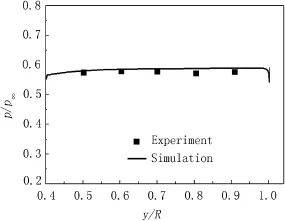
Fig.6.Base pressures at different radial positions(I=0.0038).
Fig.8 shows the comparison of area-averaged base pressures of the two models.As shown in Fig.8,the base pressure of the annulus jet model increases rapidly when the injection parameter is small.With the increase in the injection parameters,the base pressure of the annulus jet model is 3%-6% higher than that of the circular jet model.When the injection parameter reaches about 0.01,the base pressure of the circular jet model reaches a peak,but the base pressure of the annulus jet model continues to increase.With the further increase in the injection parameter,the base pressure of the annulus jet model is much higher than that of the circular jet model.When the injection temperature is 2200 K,the maximum growth rate of the base pressure of the circular jet model is only 13.0%, but the maximum growth rate of the base pressure of the annulus jet model is 29.2%.These show that the annulus jet model is more conducive to increase the base pressure.
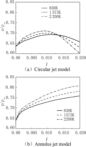
Fig.7.Area-averaged base pressures at different injection levels.
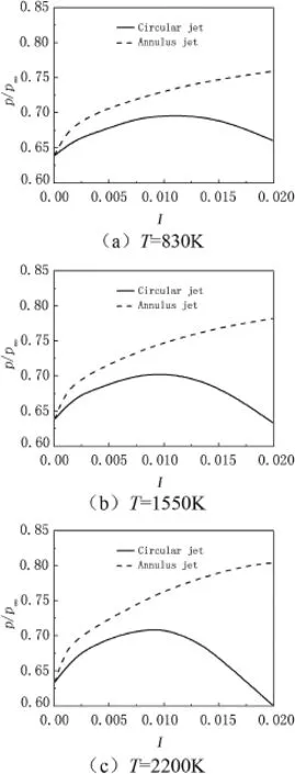
Fig.8.Area-averaged base pressure at different injection levels.
Fig.9 shows the temperature contours and streamline of base region at different injection temperatures.As shown in Fig.9,for the circular jet model,the bleed gases fow along the cracks between the annular recirculation zone and the main recirculation zone,and then fow into the shear layer.The hot gases are concentrated in the vicinity of the base.With the increase in the injection temperatures,the size of the annular recirculation zone gradually increases,meanwhile the size of the main recirculation zone gradually decreases.For the annular jet model,the annular recirculation zone is in the edge of the base,and its size is very small.Those show that the annular jet can greatly weaken the strength of the annularrecirculation zone.Since the annular recirculation zone is weakened,the bleed gases fow into the shear layer directly, and the hot gases are concentrated in the shear layer.With the increase in the injection temperature,the main recirculation zone becomes more and more fat.
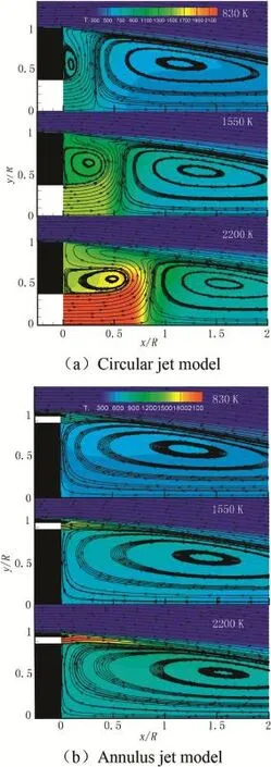
Fig.9.Temperature contours and streamline of base region at different injection temperatures(I=0.008).
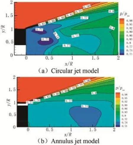
Fig.10.Pressure contours of base region(I=0.008,Tj=2200 K).
Fig.10showsthepressurecontoursofbaseregionsofthetwo models.As shown in Fig.10,the pressure in the annular recirculationzoneislowerthanthepressureinthemainrecirculation zone.For the circular jet model,the whole solid wall of the bottom is in the annular recirculation zone.For the annular jet model,because the annular recirculation zone is greatly weakened,only a small part of the solid wall of the bottom is in the annular recirculation zone,and the large part of it is in the main recirculationzone.Sothebase pressure oftheannularjetmodel is higher than that of the circular jet model.
5.Conclusions
The numerical simulations of the base fow with hot base bleed for two jet models show that the annulus jet is better for the increase in base pressure.
1)With the increase in the injection parameter,the base pressure of the annulus jet model increases.The base pressure of the annulus jet model is higher than that of the circular jet model.
2)Annular jet can greatly weaken the strength of the annular recirculation zone,and let the bleed gases fow into the shear layer directly.These make the hot gases concentrated in the shear layer.For the annulus jet model,the temperature in the shear layer becomes higher,meanwhile the temperature on the solid wall of the base becomes lower.The hot gases are concentrated in the shear layer, which is more conducive to increase the base pressure.
3)The pressure in the annular recirculation zone is lower than the pressure in the main recirculation zone.For the circular jet model,the whole solid wall of the bottom is in the annular recirculation zone.For the annular jet model, only a small part of the solid wall of the bottom is in the annular recirculation zone.
Acknowledgments
This work is supported by National Nature Science Foundation of China(Grant No.51176076).
[1]Rollstin L.Measurement of infight base pressure on an artillery-fred projectile.J Spacecr Rockets 1990;27(1):5-6.
[2]Guo XF.Exterior ballistics of base bleed projectiles.Beijing:National Defence Industry Press;1995[in Chinese].
[3]Ding ZS,Lo R,Chen SS,Liu YF.A study of some parameters infuence on performanceofdrag reduction by base burning.JBallist 1996;8(4):79-83.
[4]Bowman JE,Clayden WA.Cylindrical afterbodies at M=2 with hot gas ejection.AIAA J 1968;6(12):2429-31.
[5]Sahu J,Nietubicz CJ,Steger JL.Navier-Stokes computations of projectile base fow with and withoutbase injection.AIAA J 1985;23(9):1348-55.
[6]Gibeling HJ,Buggeln RC.Projectile base bleed technology part 1: analysis and results.AD-A258 459;1992.
[7]Choi JY,Shin E,Kim CK.Numerical study of base-bleed projectile with external combustion.AIAA Joint Propulsion Conference and Exhibit. Tucson,Arizona:AIAA;2005.
[8]Chen XH,Huang H,Zhou ZC,Zhao RX.Numerical simulation of basebleed energy affecting aerodynamicperformanceofbase bleed projectiles. Acta Armamentarii 2010;31(4):447-52 [in Chinese].
[9]Shin JR,Cho DR,Won SH,Choi JY.Hybrid RANS/LES study of basebleed fows in supersonic mainstream.In:AIAA International Space Planes and Hypersonic Systems and Technologies Conference.Dayton, Ohio:AIAA;2008.
[10]Shin JR,Choi JY.DES study of base and base-bleed fows with dynamic formulation of DES constant.AIAA Aerospace Sciences Meeting. Orlando,Florida:AIAA;2011.
[11]Mathur T,Dutton JC.Velocity and turbulence measurements in a supersonic base fow with mass bleed.AIAA J 1996;34(6):1153-9.
[12]Menter FR.Two-equation eddy-viscosity turbulence models for engineering application.AIAA J 1994;32(8):1598-605.
[13]Liang DW,Wang K.Improvement of AUSM+scheme.Acta Aerodyn Sin 2004;22(4):404-9.
[14]Yoon S,Jameson A.Lower-upper symmetric Gauss-Seidel method for the Euler and Navier-Stokes equations.AIAA J 1988;26:1025-6.
[15]Wu P,Zhao RX,Guo XF.Arc length method of grid generation and its application.J Nanjing Univ Sci Technol 2002;26(5):482-5[in Chinese].
Received 14 November 2013;revised 1 March 2014;accepted 18 June 2014Available online 22 July 2014
*Corresponding author.
E-mail address:spacecow@sina.com(W.J.YU).
Peer review under responsibility of China Ordnance Society.
http://dx.doi.org/10.1016/j.dt.2014.06.010 2214-9147/Copyright©2014,China Ordnance Society.Production and hosting by Elsevier B.V.All rights reserved.
Copyright©2014,China Ordnance Society.Production and hosting by Elsevier B.V.All rights reserved.
杂志排行
Defence Technology的其它文章
- Analysis of equivalent antenna based on FDTD method
- Infuence of high frequency pulse on electrode wear in micro-EDM
- Single channel source separation of radar fuze mixed signal based on phase difference analysis
- Combined proportional navigation law for interception of high-speed targets
- Numerical simulation of detonation of an explosive atmosphere of liquefed petroleum gas in a confned space
- Analysis on the resistive force in penetration of a rigid projectile
