Infuence of high frequency pulse on electrode wear in micro-EDM
2014-02-14XiopengLIYungngWANGFulingZHAOMenghuWUYuLIU
Xio-peng LI,Yun-gng WANG*,Fu-ling ZHAO,Meng-hu WUYu LIU
aDalian University of Technology,Dalian 116024,China
bDalian University,Dalian 116622,China
cDalian Jiaotong University,Dalian 116028,China
Infuence of high frequency pulse on electrode wear in micro-EDM
Xiao-peng LIa,b,Yuan-gang WANGb,*,Fu-ling ZHAOa,Meng-hua WUb,Yu LIUc
aDalian University of Technology,Dalian 116024,China
bDalian University,Dalian 116622,China
cDalian Jiaotong University,Dalian 116028,China
An electromagnetic coupling mathematical model is established by fnite element method and is verifed by the contrastive experiments of copper matrix Ni-TiN cylindrical coating electrode,copper electrode and Cu50W electrode.The wear mechanism of Ni-TiN/Cu composite electrode in the case of high-frequency pulse current is studied,and the infuence of the fuctuation frequency of discharge current on electrode wear in micro-EDM is found out.Compared with the electrode made from homogeneous material,the high frequency electromagnetic properties of Ni-TiN composite layer can be used effectively to inhibit the effect of high frequency pulse on the electrode and improve the distribution trend of current density.
High-frequency pulse;Electromagnetic coupling model;Ni-TiN/Cu composite electrode;Electrode wear;Micro-EDM
1.Introduction
Micro-EDM is one of the effective techniques to achieve three-dimensional(3D)complex micro-structure machining.It is a great potential precision machining technology for weapon manufacturing and micro-manufacturing felds since it can be used to process a wide range of materials and no cutting force is created during machining.
Although the micro-EDM technology has made a great progress on the applied research[1-3],the violent change of electrode shape in micro-scale seriously affects the machining quality of micro-EDM,which restricts its development.One solution is to use the composite electrode consisted of a metal rod encased in a dielectric pipe jacket [4].It can effectively avoid the discharge of side surface of electrode,but it is diffcult to make a high quality protective sleeve and to clamp the combined electrodes.Electrically conductive CVD diamond[5]and Cu-ZrB2coatings electrode[6]show better EDM Performance than that of pure copper.Wang Yuangang et al.[7]electrodeposited the ZrB2ceramic particles on the sides of copper electrode,which improves the electrical erosion resistance of electrode surface since the conductivity of deposited layer is similar to that of the substrate material,but a higher melting point exists.These research works are feasible for reducing electrode wear,but ignore the effect of micro-EDM discharge conditions on the electrode wear,especially the effect of high frequency pulse.
A mathematical model of electromagnetic feld was established in order to research the infuence of high frequency pulse on the current density distribution on electrode in the paper.Ni-TiN composite electrode of which TiN nanoparticles were as reinforcing phase in the cylindrical electrode was electrodeposited.The difference between the discharge characteristics of Ni-TiN/Cu composite electrode and Cu electrode was discussed in detail by the comparison of fnite element analysis results and experimental results. The result shows that the established model refects the electromagnetic characteristics of high frequency pulse,andthe experimental results are consistent with the simulation ones.
2.Modeling and simulation
2.1.Wear mechanism of electrode
Based on the theory of discharge breakdown[8],the shape of electrode is closely related to the distribution of electric feld strength.Because the spark discharge usually occurs randomly in the location where the strongest electric feld exists,the intensity distribution of electric feld directly affects the probability distribution of discharge points.When the machining starts,the electric feld produced by electric poles mainly focuses on the edge of the electrode,which makes the probability of discharge on the edge increase;the edge wear is very obvious.When a micro-nanosecond pulse power supply is used,the current fows from power supply to the discharge channel via the surface of electrode because of skin effect.As a result,when surface current increases,discharge probabilities of edge will accelerate,the wear of bottom edge will be rapid.Therefore,the density of electric feld is the main reason for the electrode wear[9].
2.2.Electromagnetic feld model
Finite element method is adopted to simulate the electromagnetic feld produced by the fuctuation frequency of discharge current in Ni-TiN/Cu electrode or pure Cu electrode.The model for copper matrix Ni-TiN cylindrical coating electrode is shown in Fig.1.
When a high frequency pulse voltage is applied to the gap between tool electrode and workpiece,a discharge takes place. A changing magnetic feld perpendicular to the current is generated in the electrode.Electric and magnetic felds mutually excite,which will meet Maxwell's equations for time-varying felds[10].
The transient change of electric feld produces a magnetic feld
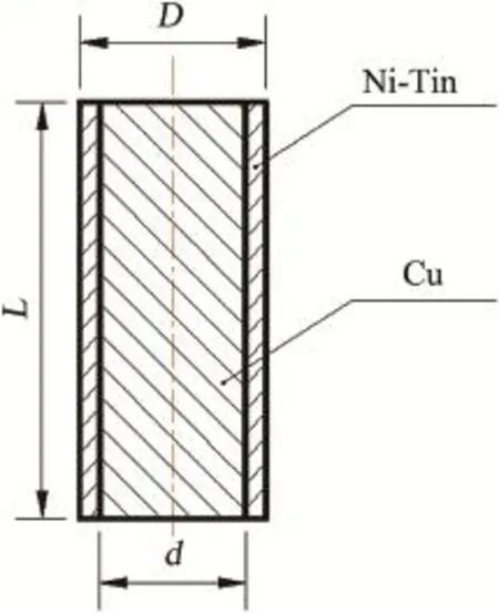
Fig.1.Structure diagram of composite electrode(longitudinal section).


where represents the electric feld vector at any point of electrode;E is the magnetic feld strength;σ is the conductivity of material; E is the electric feld intensity;and ε is the relative dielectric constant of material.
And on the basis of the change in magnetic feld and the induced electric feld intensity,E can be obtained by the following equation. where A is the vector potential of electromagnetic feld.


According to the current density and the external current density,we have The external current density: The electric and magnetic felds interact in high frequencies.The induction electromotive force caused by the magnetic feld change generates an eddy current along the entire length of conductor vortex to prevent the magnetic fux from changing.The sum of main current and the eddy current strengthens on the electrode surface.According to the above formula,the electromagnetic feld coupling formula is eventually derived.

2.3.Electromagnetic coupling simulation
Based on electromagnetic feld theory,the proposed transient coupled model of electrode is shown in Fig.2.The results are obtained in the different time transient electromagnetic felds by fnite element simulation.
The simulating conditions are that the discharge maintaining voltage is 20 V,the peak current is 2 A,the pulse duration is 1 μs,and the frequency is 0.2 MHz.In order to simplify the simulation environment,the external environment is set to deionized water domain.The diameter of Cu electrode is 0.3 mm the thickness of coating Ni-TiN is 0.02 mm;the inner diameter of Cu matrix composite electrode is 0.26 mm, the thickness of coating W is 0.02 mm.The physical parameters of the materials are listed in Table 1.
The current density distributions of pure Cu electrode, Ni-TiN/Cu compositeelectrodeand W/Cu compositeelectrode in transient magnetic feld at high frequency pulse current are shown in Fig.3.
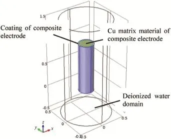
Fig.2.Composite electrode simulation model.

Table 1Physical parameters of Cu,Ni-TiN,W and deionized water.
3.Experimental design
3.1.Sample preparation
Ni-TiN/Cu composite electrode is made from ultrasonic pulse electrodepositing Ni-TiN nanocomposite plated on the side of Cu electrode[11].As the Ni layer usually peels off during the discharge process which affects the overall quality of processing,TiN nanoparticles are added to increase the combined force ofNilayerand Cu substrate.Thetechnological conditions and parameters for sample preparation are listed in Table 2.Ultrasonic power is 180 W.
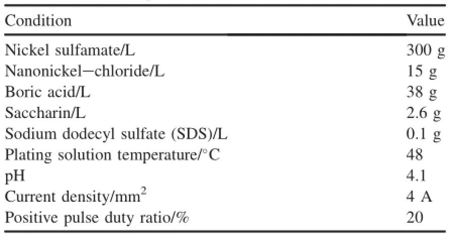
Table 2Plating solution compositions.
3.2.Sample test
Composite electrode samples are characterized by XRD (X-max20X)and SEM(EVO18).Ni-TiN nanocomposite coating(Fig.4)has fatter surface,smaller grains,homogenous distribution of TiN,compact structure.Ti element in the nanocomposite coating can be seen in Fig.5,and the percentage of TiN particle in composite coating is 6.2 wt%. Ni-TiN coating has excellent corrosion resistance and high melting point performance.The melting point of Ni-TiN is 1753°C,which was measured by high-temperature differential thermal analyzer(DTAS-2).The electrical conductivity of Ni-TiN is 14.8e6 S·m-1,which is measured by four-point probe(RTS-8).
3.3.EDM experiments
Experiments were carried out on EDM machine tool (Sodick AD30Ls)with workpieces made of stainless steel 304. The experimental conditions are listed in Table 3.Pure copper electrode,Cu50W homogeneousmaterialelectrodeand Ni-TiN/Cu composite electrode are used as tool electrodes, respectively.
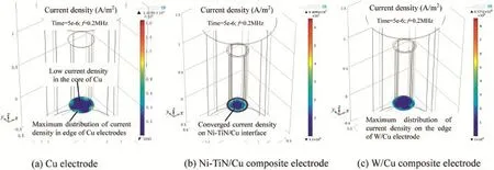
Fig.3.Current density distribution of three electrodes.
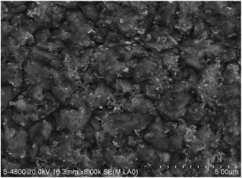
Fig.4.Ni-TiN coating surface morphology.
Fig.6 shows the cross-sections of three holes observed under Olympus microscope(SZ61).In general,the Ni-TiN/ Cu composite electrode has enhanced shape quality(Fig.6) and reduced electrode wear,as compared with the Cu50W homogeneous material electrode[12]and the pure copper electrode.
The geometrical characteristics of the drilled holes were obtained by micro-EDM deep hole drilling with tool electrodes:the inlet diameter(Din),middle diameter at the bottom (D1)and actual hole depth(H).The machining time(t)was also recorded.The experimental results are listed in Table 4.
4.Discussion
Ni-TiN/Cu composite electrode has better shape consistency,as shown in Fig.6.The experimental results are in consistent with the simulation ones(Fig.3).This may be ascribed to the fact that the shape of electrode changes in such a way as to achieve the uniform intensity of electric feld eventually.
In the process of EDM,the fuctuation frequency of discharge current is one order of magnitude than that of pulse. High frequency generates pulsed eddy magnetic feld,and the vortex electric feld occurs inside electrode.The directions of the magnetic feld produced by the eddy and current magnetic feld are opposite.Therefore the current density distribution in the cross-section of electrode is uneven,and focuses on the edge of electrode(Fig.3).
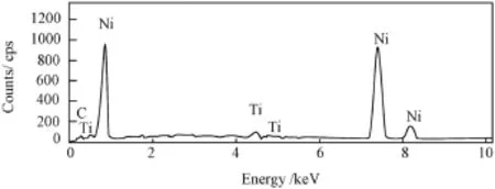
Fig.5..EDS spectrogram of Ni-TiN surface morphology.
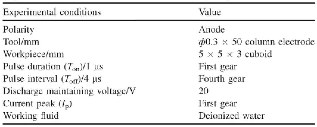
Table 3Experimental conditions of micro-EDM machining deep holes.
As the breakdown of electrode usually occurs in a location where the strongest electric feld exists,it is possible that the wear of Cu electrode takes place on its edges.With the increase in processing time,the sparking area undergoes changes,which makes the sparking conditions continuously alter and the bottom edge of electrode disappears.
The distribution of current density of Ni-TiN/Cu composite electrode is obviously different from those of Cu electrode and W/Cu composite electrode.Its current density is mainly concentrated in the interface between coating and matrix(Fig.3(b)).The difference is explained by the properties of coating.First,Ni,which is ferromagnetic material, weakens eddy current under the high frequency pulse and results in decrease of current density in the composite layer, while W as a non-ferromagnetic material has no such effect. Second,as the resistivity of Ni-TiN electrode is larger than those of Cu and W/Cu composite electrodes,a large part of the current fow to the direction of small resistance,thus it forms a concentrated region of current density in the interface between Ni-TiN layer and Cu.
The difference of melting points has some effect on electrode wear(Fig.6(a)and(b)),but compared with the temperature for pulse discharge,the effect is limited.The melting point of Cu50W homogeneous material electrode[12]is higher than that of Ni-TiN/Cu composite electrode.It can be seen from Fig.6 that Ni-TiN/Cu composite electrode has better shape consistence over the Cu50W homogeneous material electrode.According to the numerical simulation results, the fundamental cause of change of electrode wear is the current density distribution resulting from the fuctuation frequency of discharge current.
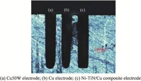
Fig.6.Holes processed by different electrodes.

Table 4Comparison of the experimental results of tool electrodes.
5.Conclusions
The infuence of high frequency pulse on electrode wear in micro-EDM has been theoretically analyzed and experimentally investigated.The main conclusions are as follows:
1)The mathematicalmodelofhigh frequency pulse discharge is reasonable,and can be used to analyze the effect of high frequency pulse and electrode material properties on the electrode wear.
2)The eddy current generated by time-varying electromagnetic feld under high fuctuation frequency of discharge current is able to change the current density on the surface of electrode,and plays an important role in the change of electrode topography during micro-EDM process.
Acknowledgment
The authors would like to thank the National Natural Science Foundation of China for fnancially supporting this research through project No.51005027.
[1]Yu ZY,Masuzawa T,Fujino M.3D micro-EDM with simple shaped electrode,part l:machining of cavities with sharp corners and electrode wear compensation.In:IEEE,editor.Proceedings,the 4th Korea-Russia International Symposium on Science and Technology,vol.3.IEEE Electron Devices Society;2000.p.102-5.
[2]Rajurkar KP,Yu ZY.3D micro-EDM using CAD/CAM.CIRP Ann 2000;49(1):127-30.
[3]Sundaram MM,Rajurkar KP.Towards freeform machining by micro electro discharge machining process.Trans 36th N Am Manuf Res Conf SME 2008:381-8.
[4]Kumagai S,Misawa N,Takeda K,Abdukarimovb ET.Plasma-applied machining of a narrow and deep hole in a metal using a dielectricencased wire electrode.Thin Solid Films 2004;457(1):180-5.
[5]Chen W,Kang XM,Gu L,Zhao WS.Research on electrically conductive CVD diamond as electrodes in micro and fne EDM.Machinery 2006;33(4):26-8[in Chinese].
[6]Guo DM,Zhang M,Jin ZJ,Zuo BX.Particle strengthening of the surface of copper electrode for electrical discharge machining.Int J Mater Prod Technol 2008;31(1):81-7.
[7]Wang YG,Zhao FL,Wang J.Wear-resist electrodes for micro-EDM. Chin J Aeronautics 2009;22(3):339-42.
[8]Schumacher Bernd M.After 60 years of EDM the discharge process remains disputed.J Mater Process Technol 2004;149(1-3):376-81.
[9]Singh A,Ghosh A.A thermo-electric model of material removal during electric discharge machining.Int J Mach Tools Manuf 1999;39:669-82.
[10]Liu JS,Xu P,Zhong HY.Electromagnetism.Changchun:Jilin People's Publishing House;2004[in Chinese].
[11]Xia FF,Wu MH,Wang F,Jia ZY,Wang AL.Nanocomposite Ni-TiN coatings prepared by ultrasonic electrodeposition.Curr Appl Phys 2009;9(1):44-7.
[12]Chen H,Zhang LX,Yu JZ,Wang WB.Experimental study on processing performance of electrode material in electric discharge machining.Mod Manuf Eng 2013;4:79-84[in Chinese].
Received 5 January 2014;revised 20 February 2014;accepted 20 March 2014 Available online 31 July 2014
*Corresponding author.
E-mail address:wygang2000@163.com(Y.G.WANG).
Peer review under responsibility of China Ordnance Society.
http://dx.doi.org/10.1016/j.dt.2014.07.007 2214-9147/Copyright©2014,China Ordnance Society.Production and hosting by Elsevier B.V.All rights reserved.
Copyright©2014,China Ordnance Society.Production and hosting by Elsevier B.V.All rights reserved.
杂志排行
Defence Technology的其它文章
- Analysis of equivalent antenna based on FDTD method
- Single channel source separation of radar fuze mixed signal based on phase difference analysis
- Combined proportional navigation law for interception of high-speed targets
- Numerical simulation of detonation of an explosive atmosphere of liquefed petroleum gas in a confned space
- Analysis on the resistive force in penetration of a rigid projectile
- Numerical simulation of base fow with hot base bleed for two jet models
