Actuator characterization of a man-portable precision maneuver concept
2014-02-09IlmrsCELMINSFrnkFRESCONIBryntNELSON
Ilmrs CELMINS*,Frnk E.FRESCONIBrynt P.NELSON
aUS Army Research Laboratory,Aberdeen Proving Ground,MD,USA
bBowhead Science and Technology,Belcamp,MD,USA
1.Introduction
The motivation for this paper is to maneuver man-portable precision munitions.In-flight airframe maneuvers are required to overcome uncompensated ballistic error sources such as launch variation and atmospheric disturbances or to engage targets in defilade and ultimately improve lethality.Manportable precision capability provides enhanced lethality at the squad level.
Various methods have been devised to course-correct the flight of projectiles[1-11].Aerodynamic[1,3,4,6,8-11]or mass[5]asymmetries are often utilized.Lateral jet thrusters are another means[2,7].Providing maneuver technologies in the man-portable,gun-launched environment is extremely challenging.The loads imparted to the electro-mechanical components during the gun launch event are high[12,13].Size,weight,power,and cost needs are difficult to meet.Manportable weapons are about 80 mm in diameter or smaller.Maneuver systems,which usually include a power source,actuators,sensors,processors,and associated electronics,must fit along with other sub-systems in this small package.Cost of these technologies must be low to ensure high volume proliferation to individual Soldiers on the battle field.Depending on caliber,the dynamic pressure available for aerodynamic control authority(essentially the projectile velocity)may be limited due to gun recoil limits on the human shoulder.Lastly,rifled guns often induce high spin rates(hundreds or thousands of cycles per second)in the projectile which can significantly stress the bandwidth requirements of maneuver technologies.This study proposes a class of maneuver concepts,based on rotational actuation,to overcome these challenges for the manportable precision problem.
Comprehensive investigation of a projectile maneuver concept implies consideration of aeromechanics,flight control,structural dynamics,and actuation technology.Actuators,the focus of this study,underpin the maneuver concept and are essential to guided flight.Actuator performance requirements are met through a fundamental understanding of actuator behavior.The response of actuators can be described with theoretical models which are driven with empirically-derived data.Electric motors are commonly applied in rotational actuation schemes and often model response by considering the applied torques(e.g.,motor,friction)in Newton’s 2nd law.Experiments conducted on actuation system assemblies(e.g.,motor,linkages,aerodynamic surfaces)can be combined with theoretical models to obtain the critical actuation technology parameters.
This study focuses on characterizing actuation technologies specific to the proposed class of maneuver concepts.Actuator experiments are conducted to identify theoretical models and to estimate the parameters of these models.Actuator performance metrics for the present application include torque,response,friction,and power requirements.Characterization of the actuation technology permits feasibility assessment,simulation of guided flight performance,and design for guided projectile demonstration.This study provides a somewhat general actuator characterization to cover a wider application space.Specific applications dictate performance requirements for more detailed actuator design.
This paper is organized as follows:maneuver concepts are first outlined,followed by a discussion of actuator experiments to include the setup,raw and manipulated data,experimental uncertainty,theoretical modeling,parameter estimation algorithm,and then the results are presented prior to summarizing the paper with conclusions and future work.
2.Concepts
While the intent is to research a maneuver technology with a wide applicability,a few general constraints may be imposed.The application under investigation is a spinstabilized projectile.Spin rates are in the range of 50-300 Hz.For the purposes of preliminary design,a 40 mm projectile was used.
Given this information,some concepts were formulated around a central theme.The common element is a rotational actuator.The idea is that small linear actuators may not be able to move the aerodynamic surfaces at rates of 50-300 Hz with high precision at low cost,but rotational actuators may.This is because a linear(reciprocating)actuator would need to constantly change direction,resulting in large accelerations which in turn require large forces,thereby driving up the actuator power.A rotational actuator would be operating at a fairly constant rotation once it is up to speed,resulting in much lower power requirements.
Fig.1 illustrates a concept using one or more wings fixed to a rotational actuator.As the projectile spins,the actuator rotates at the same rate in the opposite direction.Over one spin cycle,the wing rotates from being stowed internally within the projectile body to being fully exposed to the airstream to affect lateral maneuver(as shown in Fig.1)to again being stowed within the projectile.When the wings are exposed to the airflow,lift and drag forces are generated,which will cause the projectile linear and angular motions to change.Shifting the phase of the rotational actuator relative to the projectile spin enables maneuvering in any direction.
The magnitude of the control force can be moderated in several different ways.After adequate trajectory diversion is achieved,the wings can be rotated at a frequency different than the projectile roll rate so that no additional cumulative lateral net force is generated.Alternatively,the relative phasing of the two wings can be adjusted to reduce the net force.For example,if the wings are 180-degrees out of phase,no net transverse force would be generated since the wings would counterbalance each other.Adjusting the out of phase angle to other amounts would result in net force values between 0 and maximum.The system could be allowed to always generate the maximal diversion and then reverse the diversion direction if over steer occurs.
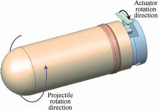
Fig.1.Rotating wing maneuver concept.
Fig.2 depicts the manner in which a two-actuator variant of this concept operates over a complete cycle of spin.The maneuver concept is viewed from the base of the projectile at eight snapshots(corresponding to a change in roll angle of 45 )throughout the spin cycle.Successive snapshots of the concept throughout the spin cycle proceed in the counter-clockwise manner around the figure.When viewed from the base the projectile spins in the clockwise direction,the actuator assembly rotates in the counter-clockwise direction.In this manner,the wings attached to each actuator rotate in and out of the projectile to provide a consistent maneuver direction.
Another concept with this rotational actuator theme is presented in Fig.3.Here,a single rotational actuator is mounted to a projectile base assembly featuring a pair of deflected fins which deploy after launch.The actuator rotates the finned base opposite the projectile spin so that the aerodynamic asymmetry of the deflected fins produces a lateral maneuver.Again,phase shifting the finned base rotation relative to the projectile rotation yields maneuvers in any direction.
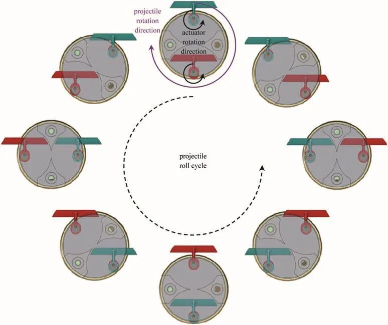
Fig.2.Snapshots(viewed from the base in earth-fixed reference frame)over one revolution of rotating wing maneuver concept with two actuators.
These maneuver concepts are on the rear of the projectile to facilitate packaging within the mouth of the cartridge case to reduce the handling and storage burden.The specific configuration of the maneuver system and aerodynamic surfaces to achieve control authority requirements for these concepts depends on the mission(e.g.,launch and flight conditions,system errors,etc.)
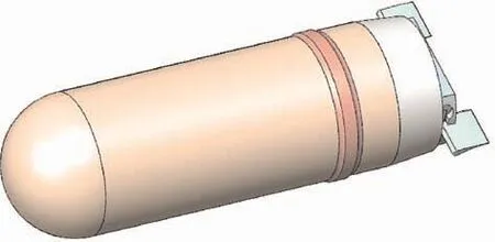
Fig.3.Rotating finned base maneuver concept.
3.Actuator characterization
Experiments were conducted to characterize the actuation technology for this class of maneuver concepts.Small,low cost gun hard motors were obtained and assembled into the prototype maneuver systems.Theoretical actuator dynamics were identified by collecting data on the input(motor)and output(spin rate)of the system.Experimental parameters included motor size,commanded spin rate,rotational direction,and inertial load.This analysis quantified the key performance metrics such as response,friction,and power requirements which can be used in maneuver concept refinement for a particular application.
3.1.Experimental setup
An apparatus was created for data collection.A market survey yielded some viable motors(manufactured by Maxon).An image of one of these brushless DC motors along with a model of the rotating wing concept and a prototype 40 mm projectile which was fired through the spark range[14]is shown in Fig.4.This motor product line goes down to 6 mm in diameter with satisfactory cost,speed and torque specifications.Electrical(e.g.,torque constant KT)and inertial(moment of inertia Ix,diameter D)data for some of these motors is given in Table 1.Shock table experiments also indicated favorable survivability characteristics.
An experimental setup was created to operate these motors unloaded and with various control mechanism(inertial and aerodynamic)loadings at different speeds in the laboratory.Fig.5 provides a schematic of the setup.A speed controller(E-flite 10-Amp Pro Brushless Electronic Speed Controller)was used to drive the three motor commutator input lines.This controller inputs a pulse width modulated(PWM)signal from a signal generator proportional to the desired spin rate and uses the voltage generated by the spinning motor to infer the spin rate(back electromotive force)for feedback control purposes.The motor was equipped with 3 Hall effect sensors for measuring response.A data acquisition board(National Instruments USB-6259)run by LabView software was used to collect the input PWM and motor signals and the output Hall sensor data.An image of this setup on the bench in the laboratory is shown in Fig.6.
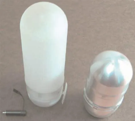
Fig.4.Image of motor with rotating wing concept and prototype 40 mm projectile.
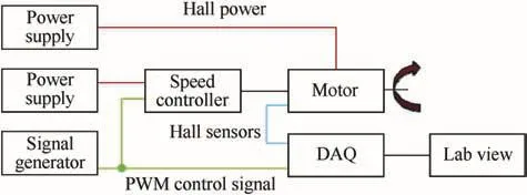
Fig.5.Schematic of experimental setup.
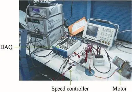
Fig.6.Experimental setup.

Table 1Motor electrical and inertial data.
3.2.Raw experimental data
Collection of actuation system input and output is necessary to derive theoretical models and to estimate model parameters.An example of the raw input data scaled to about 10 V in the data acquisition from an experiment is provided in Fig.7.The leading and trailing edge times of the motor driving signal were interrogated to within a half-sample time resolution for determining the pulse width.The motor spin rate was controlled using the pulse width of the input signal rather than the amplitude of the input signal.
A sample of the output from one of the channels of Hall sensor data is shown in Fig.8.A cycle of low(0 V)and high(5 V)signals represents one rotation.Interrogation of the Hall pulse leading and trailing edges over one rotation permits calculation of the spin rate.The sample data in Fig.8 corresponds to a spin rate of about 35.7 Hz.
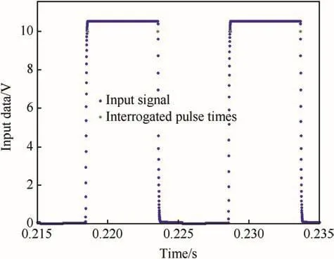
Fig.7.Raw input signal.
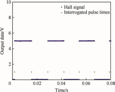
Fig.8.Raw output signal.
3.3.Experimental uncertainty
Consideration of the experimental uncertainty in spin rate is merited,especially since only Hall sensor pulses(i.e.,not a high resolution encoder)are used.A simple equation is used to relate the primary experimental measurement(time to complete one rotation,Δt)to the spin rate(˙φ)in Hz,we have

The relationship between the uncertainty in the spin rate measurement(w˙φ)to the uncertainty in the primary measurement(wΔt)is given by the following equation

This expression highlights the importance of a high data sample rate(fs).Uncertainty in spin rate on the order of 0.1 Hz may be expected at a 10 kHz sample rate for a 50 Hz spin rate.A sample rate of 200 kHz was used in the experiments(w˙φ~0.001 Hz).
3.4.Conversion to engineering units
The motor driving signals were used to obtain the system input data shown in Fig.9.The pulse width for all three signals to the motor and an average are provided.In this experiment,the controller calls for higher demand when spinning the control mechanism up followed by a lower control effort once the assembly reaches a steady-state spin rate.
The Hall sensor output was manipulated to determine spin rate.Additionally,an average spin rate was found by averaging the spin rate and time of individual Hall sensors.An example of these data is provided in Fig.10.The spin rate of the actuator reaches over 100 Hz within about 0.1 s.Fluctuation in the steady-state spin rate may be due to controller performance at this low load.One Hall sensor was not recorded during this experiment.
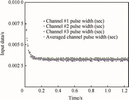
Fig.9.Manipulated input signal.
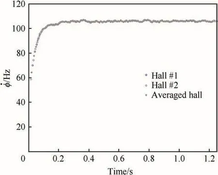
Fig.10.Manipulated output signal.
3.5.Data modeling
Inspection of the spin rate response in Fig.10 suggests that a simple model may capture the experimental data.A first order system was used to model the data in preliminary experiments.A lag,dictated by the time constant(),prescribes the manner in which the spin rate adjusts to a commanded spin rate().

Pulse width(P),rather than commanded spin rate,is the driving input in experiments due to the manner in which the experiments were conducted(=fpP).These inputs relate through a scaling(fp).
3.6.Physical modeling
Newtonian kinetics is applied about the spin axis of the maneuver system to derive the dynamic equation of motion from first principles.The dynamics are driven by the total axial moment of inertia,friction moment(friction coefficient KF),and the driving moment(torque constant KTand average current i)[15-17].

Inspection of the equivalent models in Equations(3)and(4)permits relationships between model parameters to be defined.

The time constant in the data model does not adhere to the classic definition of time constant.A more traditional time constant may by derived from the model parameters (τ =IX/KF).
3.7.Parameter estimation
Parameters in the physical models must be characterized for actuator performance evaluation and for multi-disciplinary modeling and simulation of other aspects(maneuver system control,aeromechanics,flight control)of a man portable precision munition.A variety of parameter estimation routines may be formulated for the current problem.The maximum likelihood method[18-22]was chosen based on the ease of use and attractiveness for this application.In this scheme,a likelihood function is defined.

Here,the residual(e=xM?xC)is the difference between measurements and theoretical model calculations and the residual covariance(R=E[eeT?)for the current problem represents experimental uncertainty. The number of measurements are NM.The goal of this parameter identification algorithm is to find the model parameters which optimize the likelihood function(and thereby minimize the difference between measurements and model calculations).
If model noise is neglected then some simplifications to the general maximum likelihood method can be made.The algorithm starts by inputting estimates of the initial states,parameters,and measurement uncertainty.The model is integrated with states(xC),controls(u),and parameters(θj).

This method accommodates nonlinear models.For the current problem the equation of motion in Equation(3)was used as the model withand
At times when the measurements are available,the Newton-Raphson method is used to optimize the likelihood function.Calculations are performed for the residual and Jacobian((∂xC/∂θ)).
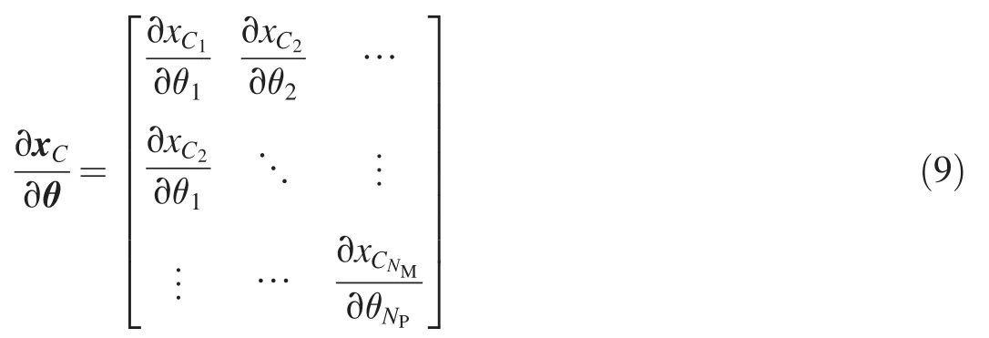
The number of parameters is NP.The Jacobian may be found analytically or numerically.Forward differencing was used in the present problem.
Parameters are corrected through the following expression.

The number of measurement samples is N.The termis often referred to as the information matrix and represents the content of useful data.The parameter estimation problem is ill-conditioned when the determinant of the information matrix is zero.
Corrections are applied to update the parameter estimates.

The model is integrated again with the updated parameters.

The residual is re-calculated.This process is iterated at each measurement update until some convergence criterion(e.g.,magnitude of residual below some threshold)is reached.Once convergence is satisfied,the updated parameter estimates are used to integrate the model forward in time until the cycle repeats at the next measurement update.In this manner,the calculated response and parameter estimates are obtained over the entire measurement history.
4.Results and discussion
Actuator experiments were conducted over a variety of conditions and multiple samples at a given condition to assess full spectrum performance and perform statistical analysis.Independent parameters were motors(6 mm,16 mm),commanded spin rate(approximately 50 Hz,100 Hz),rotation(clockwise(CW),and counter-clockwise(CCW))direction,and inertial load(motor only,added inertial).Spin rate and input pulse width data were collected for each experiment.Next,the parameter estimation routine was used to match this collected data with data model parameters(time constant,input scaling).The collected data and data model parameters,along with the derivation of the physical model[Eqs.(4)-(6)],enabled the physical model parameters(e.g.,friction,average current)to be determined.This section of the paper shows a typical example of this analysis process along with a table summarizing the results for all experiments.
An example of the measured spin rate and spin rate calculated from the parameter estimation algorithm is provided in Fig.11.The model matches the ramp-up and steady state portions of the experimental data.Errors in spin rate were usually less than 1 Hz across experimental results.Agreement between the theory and experiment validates the models and data driving the models.
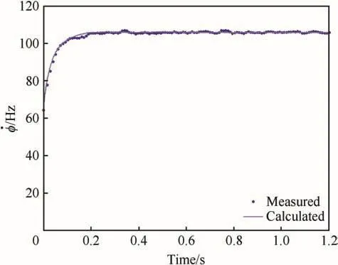
Fig.11.Measured and calculated spin rates.
The resulting parameter estimates and input data can be used to determine the current sent to the motor.Fig.12 shows that the current is higher when the actuator spins upward from rest before leveling off as the spin rate holds constant.All results indicate the power requirements are modest.
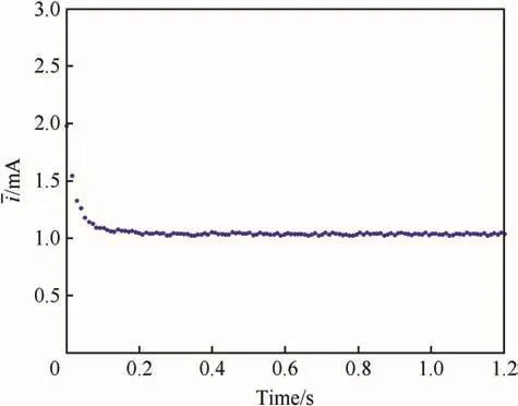
Fig.12.Current history.
Parameter estimates across the different experimental conditions are provided in Table 2.All parameters are consistent for a given condition over multiple trials.The input scaling and average current varied with commanded spin rate and motor size as expected.The direction of rotation also changed the input scaling and average current mainly for the 6 mm diameter motor at low commanded spin rate.When an additional inertia load was added to the motor assembly,its performance degraded.For this reason,a few results with higher uncertainty are presented in Table 2 for this situation.

Table 3Summary statistics of maneuver system parameters.
Friction coefficient and time constant only varied according to the physical configuration.For this reason,the statistics were calculated and are given in Table 3.Inspection of these data demonstrates that the friction and time constants increase with motor size.The standard deviations of all parameters are within 10%of the mean.
The estimates of friction coefficient are useful for predicting and manipulating the dynamic response of the maneuver system.The average current permits battery sizing.The input scaling allows precise spin rate setting for future experiments.Finally,the time constant provides a metric for the system response time.The average current,input scaling,and time constant are specific to the commercial speed controller used in the experiments.
This study provides general actuator performance indicators for a class of maneuver concepts.Overall,the results indicate that the battery requirements and the friction and spin rate characteristics of this actuation scheme are satisfactory for low loadings.
The practical inertial(and potentially aerodynamic)loading,however,may demand an improved controller or motor with higher torque.Maneuver concept refinement for a particular application dictates the detailed actuator design.
5.Conclusions and future work
This paper outlined the actuator characterization of maneuver concepts for man-portable precision munitions.Multiple concepts,based on a common theme of aerodynamic control with a rotational actuator,were formulated.The specific details regarding practical implementation of these concepts for a particular mission must consider additional factors such as the control authority needed to deliver the lethal payload.
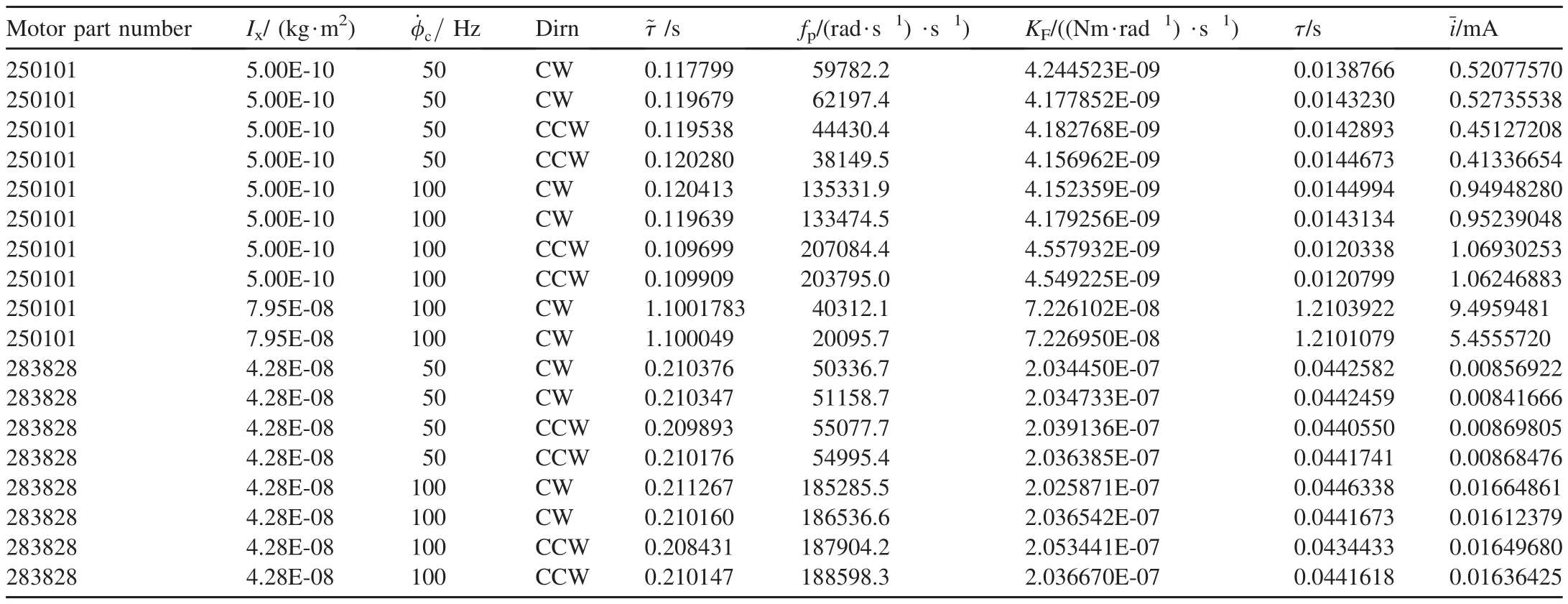
Table 2Individual Experiment maneuver system parameters.
Experiments were conducted to assess actuator performance.This paper provided the experimental setup along with the raw and manipulated data.Experimental uncertainty was considered.The data and physics-based models of the actuation system were composed.A parameter estimation algorithm was introduced.Satisfactory matches between the experimental data and theory provided some verification of the actuator models as well as numeric values for the parameters.These models and data are essential to achieve the actuation performance goals and multi-disciplinary simulation of the man portable precision munition.
The electro-mechanical design and analysis of actuator technologies in this paper suggest feasibility with regard to cost,size,bandwidth,response and power(even with a commercial controller).Overall,the preliminary results indicated the favorable characteristics of these maneuver concepts;however,further investigations must be performed.The dynamic behavior of the maneuver concept within a spinning body and under realistic aerodynamic loadings(e.g.,in a wind tunnel)must be examined.The rotating wing and finned base concepts also need further refinement of electro-mechanical and control design.A careful survivability assessment must be made.The final task to enabling the maneuver of a manportable precision munition is free-flight experimentation.
[1]McMichael J,Lovas A,Plostins P,Sahu J,Brown G,Glezer A,Microadaptive flow control applied to a spinning projectile,AIAA-2004-2512.
[2]Cooper G,Costello M.Flight dynamic response of spinning projectiles to lateral impulsive loads.J Dyn Syst Meas Control 2004;126:605-13.
[3]Moorhead JS.Precision guidance kits(PGKs):improving the accuracy of conventional cannon rounds.Field Artill;Jan.-Feb.2007:31-3.
[4]Celmins I.Design and evaluation of an electromechanical actuator for projectile guidance.Aberdeen Proving Ground,MD:U.S.Army Research Laboratory MR-672;2007.
[5]Rogers J,Costello M.Control authority of a projectile equipped with a Controllable Internal Translating mass.J Guid Control Dyn 2008;31(5):1323-33.
[6]Massey KC,Silton SI.Combining experimental data,computational fluid dynamics,and six-degree of freedom simulation to develop a guidance actuator for a supersonic projectile.J Aerosp Eng 2009;223:341-55.
[7]Davis B,Malejko G,Dorhn R,Owens S,Harkins T,Bischer G.Addressing the challenges of a thruster-based precision guided mortar munition with the use of embedded telemetry instrumentation.ITEA J 2009;30:117-25.
[8]Fresconi F,Cooper GR,Celmins I,DeSpirito J,Costello M.Flight mechanics of a novel guided spin-stabilized projectile concept.J Aerosp Eng 2011;226:327-40.
[9]Fresconi FE.Guidance and control of a projectile with reduced sensor and actuator requirements.J Guid Control,Dyn 2011;34(6):1757-66.
[10]Cooper GR,Fresconi FE,Costello MF.Flight stability of an asymmetric projectile with activating canards.J Spacecr Rockets 2012;49(1):130-5.
[11]Fresconi FE,Harkins T.Experimental flight characterization of asymmetric and maneuvering projectiles from elevated gun firings.J Spacecr Rockets 2012;49(6):1120-30.
[12]Brown TG,Davis B,Hepner D,Faust J,Myers C,Muller P,et al.Strapdown microelectromechanical(MEMS)sensors for high-g munition applications.IEEE Trans Magn 2001;37(1):336-42.
[13]Carlucci DE,Frydman AM,Cordes JA.Mathematical description of projectile shot exit dynamics(set forward.J Appl Mech 2013;80.p.031501-1-9.
[14]Guidos BG,Celmins I.The 40-mm M433 Projectile Aerodynamics Obtained from Spark Range Firings.Aberdeen Proving Ground,MD:U.S.Army Research Laboratory TR-4619;2008.
[15]Pillay P,Krishnan R.Modeling,simulation,and analysis of permanentmagnet motor drives,part II:the brushless DC motor drive.IEEE Trans Ind Appl 1989;25(2):274-9.
[16]Hemati N,Leu M.A complete model characterization of brushless DC motors.IEEE Trans Ind Appl 1992;28(1):172-80.
[17]Rigatos GG.Particle and Kalman filtering for state estimation and control of DC motors.ISA Trans 2009;48:62-72.
[18]Chapman G,Kirk D.A new method for extracting aerodynamic coefficients from free-flight data.AIAA J 1970;8(4):753-8.
[19]Whyte RH,Mermagen WH.A method for obtaining aerodynamic coefficients from Yawsonde and radardata.J Spacecr Rockets 1973;10(6):384-8.
[20]Hathaway W,Whyte R.Aeroballistic research Facility free flight data analysis using the maximum Likelihood Method.Eglin Air Force Base,FL:AFATL-TR-79-98;Air Force Armament Laboratory;December 1979.
[21]Iliff K.Parameter estimation for flight Vehicles.J Guid 1989;12(5):609-22.
[22]Klein V,Morelli EA.Aircraft System Identification.Reston,VA:AIAA Education Series;2006.
杂志排行
Defence Technology的其它文章
- Shock tube design for high intensity blast waves for laboratory testing of armor and combat materiel
- Formation of explosively formed penetrator with fins and its flight characteristics
- Experimental investigation of a cook-off temperature in a hot barrel
- Formulation development and characterization of cellulose acetate nitrate based propellants for improved insensitive munitions properties
- Deconsolidation and combustion performance of thermally consolidated propellants deterred by multi-layers coating
- Burning characteristics of microcellular combustible objects
