A passive method to stabilize an airborne vehicle
2014-02-09TimoSAILARANTAAriSILTAVUORI
Timo SAILARANTA*,Ari SILTAVUORI
aDepartment of Applied Mechanics,Aalto University,P.O.Box 14400,FI-00076 Aalto,Finland
bAero RD Ltd,Otakuja 3,FI-02150 Espoo,Finland
1.Introduction
An unguided vehicle’s atmospheric flight is sensitive to external disturbances particularly at the initial stage of a trajectory.The deviations at the early phase may become large at the end of a flight path.Furthermore,the guided vehicles may fl y part of a trajectory without an active flight controlling device,and therefore some additional damping may be required.Random disturbances cause vehicle oscillation about the centre of the mass,and this should be damped out as soon as possible.One way to relieve disturbance effects is to use a smart structure approach.A good example is a gimballed nose which reduces the nose lift.This subject has been studied extensively by Goddard[1],Kranz[2],Schmidt and Donovan[3],Barrett and Stutts[4],and Costello and Agarwalla[5].Costello and Agarwalla[5]used 6-DOF computations to show that the impact point accuracy can be significantly improved by means of a moveable nose.
Another approach for passive flight control is to use an internal moveable mass in the vehicle,e.g.in the studies published at least by Hodapp[6],and Frost and Costello[7].A further approach is to allow lengthening of the vehicle body in flight thus obviously benefiting the vehicle’s damping properties,which has also been one of the topics of this branch of science.
The capability of flexibly mounted fins to dampen such disturbances is studied in this paper.The effect of deformable fins on a vehicle’s passive control is documented by Underhill[8].However,in this paper the fins are assumed to be rigid and also very light compared to the entire vehicle mass and no aeroelastic phenomena are considered.Additionally,the vehicle is assumed to be sufficiently rigid that the fin movement initiates no unwanted resonance phenomena.
De flecting fins may be attached to the nose-part of a vehicle to provide obviously the same flight behaviour;however,the tail-mounted fins are given closer attention in this study.A flexible hinge-line location is varied and the effects on a vehicle’s dynamics are investigated by means of linear theory and 6-DOF simulations.In practice,variation in the longitudinal position of the hinge-line in computational studies is carried out by chancing a gain value.The values applied for the fin movement damping ratio in the simulations are assumed to be achieved mechanically and/or with the aid of aerodynamic fin damping.Obviously the flexible fin attachment may require a fin-locking mechanism under some circumstances before the free-flight phase of a vehicle.
2.Computational model and vehicle schematics
The dynamics of an airborne fin-stabilized vehicle is first studied using the linear theory.The results obtained are then verified by 6-DOF simulations.The 6-DOF equations are written in a non-spinning frame and a typical setup is employed as documented in Ref.[9].
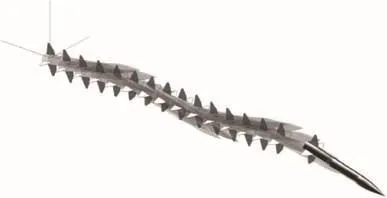
Fig.1.Airborne vehicle oscillatory behaviour after a disturbance.
An example of a vehicle oscillation after a disturbance(a launch for example)is given in Fig.1.
The short-period dynamics of a vehicle is augmented and the approach in this study is to delay the fins’deflection.The turning lag of the fins is modelled by applying a second-order transfer function,and a damping ratio ζfand a natural frequency ωfare chosen in such a way that the proper lag is obtained for a disturbance rejection.The stabilizing fins are assumed to deflect with a body angle of attack due to the air pressure.A “commanded”deflection(corresponding to a steady-state value)is obtained from a relation:

where α in Eq.(1)denotes a vehicle’s total angle of attack,which is the angle between a velocity vector and a body centreline.Fig.2 illustrates a body-fixed frame and the angle of attack defined.The gain Kpvalue is determined by the hinge-line location,fin details,and flexible joint properties,etc.
The fin numbering system and positive turning directions applied in the study are depicted in Fig.3 as viewed from the rear of a vehicle.A fin positive deflection causes an anticlockwise rolling moment,which is another definition used in the literature but no consensus exists concerning the issue(Zipfel[10]).
An equivalent fin concept is applied and,for example,a corresponding pitch deflection for the geometry in Fig.3 is obtained from the following formula
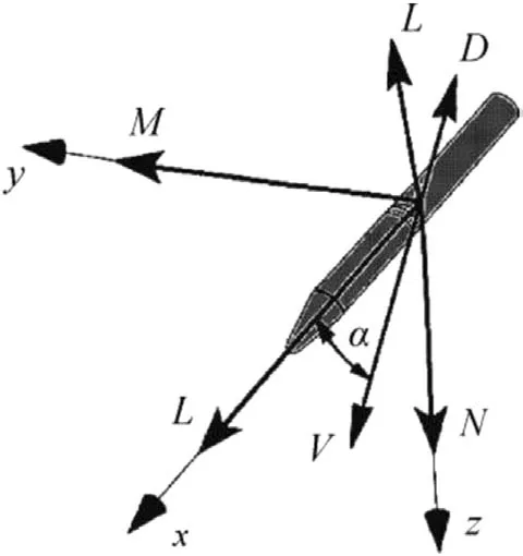
Fig.2.The vehicle body-fixed coordinate system.Positive moment directions are also depicted.The total angle of attack α is the angle between the xb-axis and the velocity vector V.The applied aerodynamic forces present are those in a wind coordinate system(D=Drag and L=Lift).
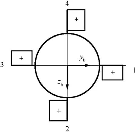
Fig.3.Fin numbering system and positive deflections viewed from the rear of vehicle.

The positive equivalent fin pitch deflection causes a negative normal force Z and a negative nose down-pitching moment M.In reality,individual fins may either turn separately,or opposite fins may be connected and turn about the same axis.The latter arrangement might provide adequate structure firmness needed at high speeds.
The equivalent true deflection angle of the fin is delayed from the command and it is obtained through a second-order connection

Eq.(3)is assumed to take into account inertial,mechanical and aerodynamic contributions.An example of a finstabilized vehicle tail geometry and a deflected fin is shown in Fig 4.
The linearized vehicle system studied is shown in Fig.5.The system impulse responses and pole-zero maps are obtained based on the structure shown.
The simplified airframe linear transfer function used in the study is

The simplified form basically ignores one fast zero which has no effect on pole-positions studied and the approach is considered adequate for the purposes of this study.
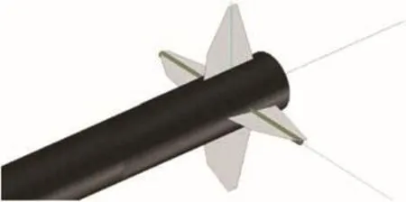
Fig.4.Airborne vehicle fin deflection(the left horizontal one)during an oscillation after some external disturbance.
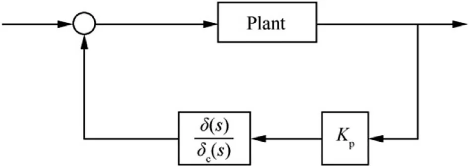
Fig.5.Linearized system studied.
The dimensional derivatives present are
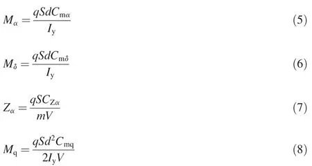
The whole closed-loop transfer function is

The passive controlling system introduced does not include nor need an integral term to make a disturbance vanish.Nevertheless,a vehicle must possess static stability and the gain Kpmust be properly chosen to not cause system instability.
The turning effect of the fins on the 6-DOF simulation aerodynamics is still to be addressed and the coefficients applied are obtained from the connections

Finally,the dimensions and other physical properties of the generic vehicle studied are given in Table 1.The numbers given resemble the data of a mortar projectile with 6 or 8 fins.The flexible fins attachment setup is assumed to provide the expected control authority and the control derivatives given in Table 1 reflect an overall capacity of the entire finset.
Besides angle of attack,a deflection angle of an individual fin may depend on fin’s bank angle and a mutual interference between the fins.However,the pattern changes if opposite fins are connected or if the fin-set is a single solid unit gimballed to the projectile base.Obviously the schemes mentioned are somewhat different and some fin-set and/or fl ow- field asymmetries may appear depending on the arrangement.Possible consequences are considered later in this study.
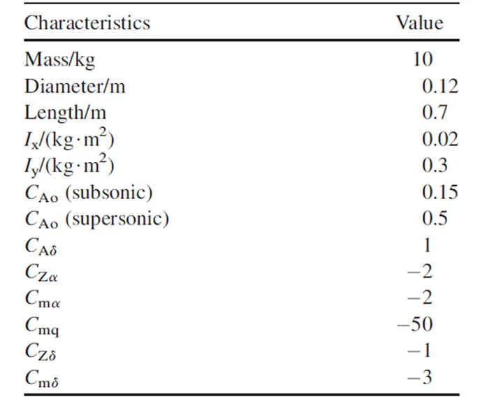
Table 1The main dimensions and physical properties of an example vehicle.
3.Results and discussion
3.1.Linear theory study
The linear method approach was first applied to determine the system response and the most important dependencies.An example vehicle velocity was taken to be 400 m/s and the air density was 1.2 kg/m3.The damping ratio ζfvalues of the fin turning were 0.7 and 0.35 in the simulations.The higher damping ratio may not be achieved in practice and the system performance was examined also for the lower one in a preliminary analysis.The natural frequency ωf(0.100 rad/s)and the gain Kp(0.-0.75)were also varied in the study.
Fig.6 shows the frequency domain pole-zero map obtained for the damping ratios chosen when the natural frequency of the fin turning is 50 rad/s and the gain Kpgoes from 0 to-0.75.The fixed-fin(Kp=0)pole-pairs are topped by zeros in Fig.6;the other results shown are obtained for gain values Kp<0 and stand for the actual fin turning cases.The zeros on the uncontrolled vehicle poles to the right are present owing to the realization of the transfer function algebra of the software applied.Nevertheless,the zero circle-symbols conveniently mark the open loop poles and are not removed from the figure.
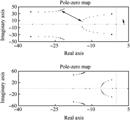
Fig.6.Pole-zero maps of the system for the damping ratios 0.7(on top)and 0.35.The gain Kpgoes from 0 to-0.75 and the slow pole-pair travels at first to the left and finally one of the pair ends up in the unstable right half-plane.
The negative value of gain Kpindicates that,in the case of a vehicle“nose-up”angle,the equivalent fin pitch deflection is a negative “leading-edge down”.A hinge-line location forward from the fins’aerodynamic centre is an obvious choice to enable the fin turning direction.The positive Kpvalues did not generate the sought vehicle damping ratio enhancement and were rejected from the studies.
The upper graph in Fig.6 is for the fin turning damping ratio of 0.7 and the poles for the gain value Kp=-0.5 are indicated with a double-arrow.The gain value was adopted for further studies since it exhibits good performance as well as some margin that takes into account a fin’s aerodynamic centre travel with Mach number and a fin’s angle of attack.Also an in-flight varying kinetic pressure is tolerated and for example a velocity growth of about 10%will increase the gain up to(absolute)value-0.6;with the increase in gain,the poles still remain in the left half-plane of the frequency domain.
In Fig.6 the associated slow pole-pair of the vehicle is seen to move at first to the left and closer to the real-axis which increases the vehicle damping ratio.However,with increasing gain(absolute)value,the pole-pair moves to the real axis and another one back to the right and locates in the frequency domain origin when Kp=-Cm∝/Cmδ=-2/3.In other words,the equivalent fin steady-state turning would be 2/3 of the angle of attack with the gain value and a vehicle would possess a neutral stability.Finally,an unstable pole location corresponding to the gain value Kp=-0.75 is indicated with an arrow on the right half-plane in Fig.6(the upper graph).
The corresponding behaviour obtained for the lower damping ratio of 0.35(the graph below in Fig.6)is basically similar,but the performance is not as good as in the case of the high fin damping ratio.The slow system pole-pair on the right does not move to the left as much as desired.Some improvement though is achieved again with respect to an uncontrolled vehicle response.
The fin natural frequency ωfchosen should not be too high since it leads to a failure of the delayed command controlling strategy.In the time domain,the deflecting fins would only spoil a basic harmonic oscillation without a particular effect on the damping history.In the frequency domain,the vehicle’s associated poles would essentially move towards the origin with an increasing absolute value of the gain Kp;the increased damping ratio sought is not attained.
Additionally,too low a natural frequency ωfleads to a loss of the control authority since a vehicle oscillation is then not reached adequately.In the frequency domain,this means that a vehicle’s associated poles do not shift much when the gain Kpabsolute value is increased;in the end,the gain only makes a turning fin’s associated pole move to the unstable region on the right.The fin turning associated pole-pair is seen at the left in Fig.6.
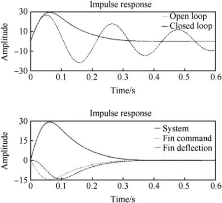
Fig.7.Time domain impulse responses of the closed-loop and open-loop systems(on top).The lower graph shows the closed-loop response again with the fin deflection data.
Fig.7 shows the linear open and closed-loop impulse responses,fin command and true fin turning time histories for values ζf=0.7, ωf=50 rad/s and Kp=-0.5.The corresponding frequency domain closed loop result is shown in Fig.6(on top)with the double-arrow.The damping ratio related to the root positions pointed out is quite high and the controlled vehicle disturbance in Fig.7 is seen to dampen out smoothly in a short time.
The vehicle open-loop poles in Fig.6 are those shown to the right with circle-symbols(zeros).The uncontrolled vehicle damped natural frequency is seen to be about 30 rad/s and the real axis value is about 2.The damping ratio is defined to be a ratio of the real part and an undamped natural frequency and the value achieved is hence only 0.07.The corresponding oscillatory time-domain open-loop result with a comparable oscillation period time 0.21 s is shown in Fig.7.An example of such a badly damped vehicle swerve motion is sketched in Fig.1.
The equivalent fin turning time histories shown with the closed-loop response(the graph below in Fig.7)also behave smoothly.The commanded and true equivalent fin deflections shown are obtained with system modifications of moving the Kpelement and also the lag transfer function into a feedforward part of the loop in Fig.5.In practice,the delay of a fin deflection is seen to reduce vehicle’s pitch stiffness at the returning phase after a disturbance which prevents overshoot phenomena.A vehicle may possess unnecessary large pitch stiffness(or a static margin)to ensure a stable flight also in the transonic speed regime.
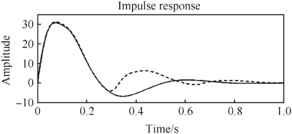
Fig.8.Time-domain linear and nonlinear system impulse responses.
3.2.Nonlinear simulations
Trajectories were simulated with initial disturbances q= ±300°/s present.An agreement of the impulse responses with given results in the linear theory was found to be excellent for the high damping ratio ζf=0.7.
The result equivalence is still quite reasonable for the low fin turning damping ratio ζf=0.35(ωf=50 rad/s and Kp=-0.5).The vehicle impulse response time histories of the first second after a disturbance are shown in Fig.8 in which the 6-DOF result is marked with the dashed line.The disturbance is seen to vanish in about 0.5 s.
The vehicle’s neutral behaviour for the gain value Kp=-2/3 was detected in the 6-DOF simulations too,and the angle of attack and fin deflection histories are given in Fig.9.The 6-DOF result shown corresponds with the slow pole location in the frequency domain origin(see Fig.6).After the transient phase the vehicle ends up in a trajectory of gradually increasing angle of attack.The growth finally stops when a set limit(±10°)for the fin turning is reached after about 0.6 s of flight.The damping capacity is also lost at that point and the vehicle is seen to oscillate about a new equilibrium point.
The high gain value Kp=-2/3 may be used to stop some disturbance caused motion since pitch damping moment coefficient has a quite large negative value.However,a steady state angle of attack after a transient will depend on the control action initiating time;the zero angle of attack is just another indefinite state of equilibrium.
A higher Kpgain absolute value makes the vehicle unstable in the 6-DOF simulations,as predicted by the linear analysis with the right half-plane pole present(see Fig.6).
3.3.System stability considerations-time delay
A system’s stability may be adversely affected if some nonmodelled phenomena are present in an examined loop.The system observed in this paper would,as an active controlling setup,become unstable with for example a dead-time present.The dead-time might be associated with the beginning of the fin’s turning movement.
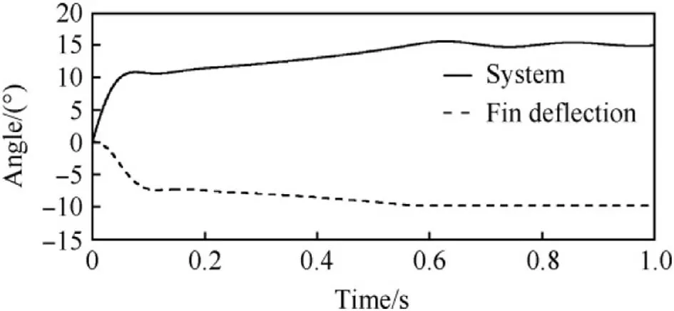
Fig.9.Vehicle neutral behaviour as a function of the time.The gain value Kp=-2/3 indicates the fin deflection as a fraction of the angle of attack.The corresponding result in the frequency domain is the pole at the origin.
However,the system constructed is a passive one without any command or feed-back memory in the loop.This means that erroneous commands do not spoil the control system and it is able to function properly right away when some possible fin turning related mechanical threshold value is exceeded.This was also proven in the 6-DOF studies.Realization of the simplified system seems to be robust and the non-modelled delays obviously present in reality are not expected to cause difficulties.
The active and passive control system performances are depicted in Fig.10 with a dead-time value of 0.03 s.The control setup values were ζf=0.7ωf= 50 rad/s and Kp=-0.5 and an active control system was imitated in the study by making use of a command memory bin;the equivalent fin deflection command was computed again according to Eq.(1).The pure time-delay is seen to make the active system oscillate.
The controlling scheme described might be applicable to damp,for example,ejected vehicle movement from an aircraft and prevent a nose-up manoeuvre following the initial nosedown angular velocity at launch.However,some ballistic vehicles may also need a trajectory angle correction after a disturbance to minimize dispersion.A properly chosen deadtime before initiating the control phase also allows a reversal correction action to take place before settling of the oscillation.The trajectory correction mechanism is thus different from the one of the moveable nose;the moveable nose reduces the nose lift and the first maximum yaw with a reduced dispersion as a consequence.
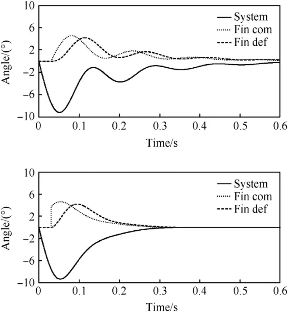
Fig.10.Active(top)and passive controlling system behaviour with a 0.03 s dead-time present in the loop.
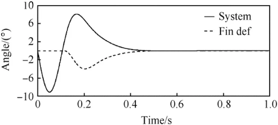
Fig.11.Passive controlling system behaviour with a 0.1 s dead-time present in the loop.
Fig.11 shows the system response with a half period time delay before the fins’deflection.The initial disturbed transient phase is followed by a correction manoeuvre to the opposite direction.The trajectory angle time histories for delayed and not delayed control action cases are depicted in Fig.12.A ballistic vehicle with the dead-time of 0.1 s is seen to return back to an initially set flight path which is governed mainly by the gravity after the transient phase.
A guided vehicle with an active controlling system would obviously be seriously unstable with the long 0.1 s dead-time present in the system.
3.4.System stability considerations-aerodynamic coupling
Another potential system instability source not included in studies so far is an aerodynamic coupling called the Magnus phenomena.Some amount of coupling is probably present in flight,at least in the case of a vehicle spinning around its centreline.The delayed and possibly asymmetrical fin deflections together with a somewhat asymmetric fl ow- field are assumed to couple the pitch and yaw channels,and this is addressed with another equivalent fin command in the 6-DOF simulations.The command is oblique to the actual controlling command and is obtained from a relation

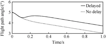
Fig.12.Vehicle flight path angle after an initial disturbance with and without dead-time present in the loop.
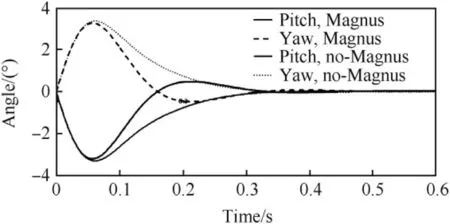
Fig.13.Magnus phenomena effect on the system responses.
The system was found to tolerate quite large erroneous commands.Fig.13 shows the system responses in the cases of no Magnus phenomena present and on the other hand when the Magnus gain KpMagis as much as 0.25.The vehicle controlling moment vector produced by the fin-set tilts 26.6°owing to the coupling in this case(seen from the rear of the vehicle).The vehicle spins around the centreline at 1 rps and the initial angular velocity disturbances around the y-and zaxes are q=r=-100°/s.Fig.13 gives the pitch and yaw components of the total angle of attack in the non-spinning coordinate frame shown in Fig.2.The Magnus phenomena are seen to cause some over-shoot but otherwise the damping time is the same.However,it seems that a moderate vehicle spinning together with properly chosen fin response properties might also enable a trajectory angle correction action before a disturbance settling.
4.Conclusions
Based on the results obtained,it seems to be possible to reject disturbance effects on an airborne vehicle flight by a suitable choice of fin attachment location and properties.Both the linear and non-linear methods give results which support this finding.
The trajectory correction mechanism is different from the one of the moveable nose;the moveable nose reduces the nose lift and the first maximum yaw with a reduced dispersion as a consequence.The approach presented in this study decreases vehicles’pitch stiffness in a controlled manner and the effect on a trajectory depends on the initiating time of the controlling action.
The passive system presented was found to be quite robust with respect to system time-delays and an aerodynamic coupling.The method provides good damping properties and also a trajectory correction action following some initial transient.The results encourage further studies on the topic.Particularly multi-body analysis with a detailed fin dynamics model is needed in order to validate the discussion presented in this paper.A Monte Carlo analysis using the more advanced system model would provide a confidence needed to move on to possible experimental phase of the research work.
[1]Goddard RH.Apparatus for steering aircraft.U.S.Patent,2594766.1952,p.4-29.
[2]Kranz W.High velocity body having telescopic nose tip.U.S.Patent,4756492.1988,p.7-12.
[3]Schmidt E,Donovan W.Technique to reduce yaw and jump of finstabilized projectiles.J Spacecr Rockets 1998;35(1):110-1.
[4]Barrett R,Stutts J.Modeling,design and testing of a barrel-launched adaptive munition.In:Proceedings of 4th Annual Society of Photo-Optical Engineers Symposium on Smart Structures,San Diego CA.New York:Society of Photo-Optical Engineers;March 1997.
[5]Costello M,Agarwalla R.Improved dispersion of a fin-stabilized projectile using a passive moveable nose.ARL-CR-464.US Army Res Laboratory;2000.
[6]Hodapp A.Passive means for stabilizing projectiles with partially restrained internal members.J Guid Control 1989;12(2):135-9.
[7]Frost G,Costello M.Control authority of a projectile equipped with an internal unbalanced part.ARL-CR-555.US Army Research Laboratory;November 2004.
[8]Underhill DA.An unconventional technique for decreasing the dispersion of unguided projectiles.In:5th International Symposium on Ballistics,Toulouse,France;April 16-18,1980.
[9]Laine S,Sailaranta T.A six degree-of-freedom trajectory model.Helsinki University of Technology,Laboratory of Aerodynamics;1995,ISBN 951-22-2766-5.Report No.B-47,Series B.
[10]Zipfel PH.Modeling and simulation of aerospace vehicle dynamics.American Institute of Aeronautics and Astronautics;2000.AIAA Education Series.
杂志排行
Defence Technology的其它文章
- Shock tube design for high intensity blast waves for laboratory testing of armor and combat materiel
- Formation of explosively formed penetrator with fins and its flight characteristics
- Experimental investigation of a cook-off temperature in a hot barrel
- Formulation development and characterization of cellulose acetate nitrate based propellants for improved insensitive munitions properties
- Deconsolidation and combustion performance of thermally consolidated propellants deterred by multi-layers coating
- Burning characteristics of microcellular combustible objects
