分布式发电反孤岛控制的自动加速相移方法
2014-01-28张榴晨MaryKayeChrisDiduch
张榴晨,Mary Kaye,Chris Diduch,尹 俊
(纽布伦斯维克大学 电气与计算机工程系,加拿大 弗雷德里克顿 E3B5A3)
1 Introduction
With increasing applications of distributed generation(DG)systems,inverters have evolved from a traditional“power conversion device”into a“system integrator”.One of the most important functions of grid-connected inverters for DG systems is executing protection algorithms to meet the requirements for grid interconnection;particularly protection from“islanding”.Islanding is a condition in which DG systems continue to supply stable real and reactive power to local loads at sustained voltage and frequency,while the main electric power system is disconnected from the point of common coupling(PCC)to which DG systems are connected.Grid interconnection standards require that a DG be de-energized at the point of DG connection as shown in Figure 1 when an island is formed[1].Numerous approaches have been developed for automatically detecting the islanding formation and triggering protection;generally referred as anti-islanding techniques.
Anti-islanding techniques can be classified into two categories:remote techniques and local techniques[2-4].While the remote islanding detection methods rely on communications between a centralized controller and distributed generators,local techniques tend to be more cost effective relying only on measurements and conditions at the DG site to implement anti-islanding algorithms and thus are widely used in DG inverters.Local techniques may be further classified as passive and active methods.

图1 分布式发电系统与电力系统的互联关系Figure 1 Interconnection of a DG system with electric power system(EPS)
Generally,passive islanding detection techniques have larger non-detection zones(NDZ)than their active counterparts.Passive schemes such as over/under voltage protection and over/under frequency relay protection(OFR/UFR)still play a very important role in the islanding prevention.Newer passive detection methods have been proposed,including:rate of change of output power,rate of change of frequency,rate of change of frequency over power,phase jump detection,harmonics detection,impedance identification and power spectral density[2-4].Recent development in passive islanding detection has resulted in reduced NDZ[2,4-5].
Active anti-islanding techniques purposely inject perturbations into the DG’s output and detect the changes in the DG systems.Frequency or phase shift methods have been proposed and devel-oped,including slide-mode frequency shift(SMS)method[6],active frequency drift(AFD)method[7],active frequency drift with positive feedback(AFDPF)method[8],and automatic phase shift(APS)method[9]).These methods use positive feedback as a means to quickly shift the frequency of a DG unit away from its nominal value until over/under frequency protection is triggered.Most of commercial DG inverters adopt active anti-islanding techniques.Improvements have been sought to reduce the NDZ,shorten the islanding detection time,and reduce the disturbances to electric power systems.
In this paper the authors propose an improved anti-islanding method for inverter-based DG systems called the accelerated automatic phase shift(AAPS)method.The method achieves significantly shortened times for detecting an island.Commercialized DG inverters using AAPS have passed anti-islanding tests for certification against UL and CSA standards for grid interconnection.
2 APS and AAPS Algorithms
The automatic phase shift method is actually a modified slide-mode frequency shift method with additional phase shift to break a possible stable operating point and drive the frequency into the OFR/UFR tripping window at the onset of an islanding condition.APS changes the phase shift angle,θAPS,of the inverter output current when there is a frequency deviation at the inverter’s terminal voltage[9],as follows,

Here,αis a constant scaling factor,fis the detected frequency,fnis the nominal frequency of the power system(i.e.,60Hz or 50Hz),andθ0is the additional phase shift,i.e.a positive feedback introduced according to the frequency changeΔfssbetween two adjacent steady states,

and

where Δθis a constant,andθ0(k)=0,∀k≤0.
The additional change,θ0(k),ensures a continuous shift in frequency and guarantees that the OFR or UFR is eventually triggered when islanding occurs.However,it is difficult to determine every stable operating point outside of the OFR/UFR tripping window once an island occurs,which affects the effectiveness of the positive feedback(i.e.the additional phase shift).A small threshold could lead to zero additional phase shift and a large threshold may cause a phase shift in the inverter’s normal operation.Moreover,because this additional phase shift is only added at each possible stable operating point,the APS algorithm may respond slowly and even fail under certain load conditions.
An improved algorithm called the accelerated automatic phase shift method is proposed by the authors[10].It forces additional phase shift when an islanding condition is hypothesized and evaluates the impact of every phase shift action on the period of the inverter output voltage.This algorithm causes an accelerated change in the phase shift for inverter-based DG systems when an islanding condition occurs and very small phase changes when the grid remains connected.The AAPS algorithm defines a basic phase shift between the output current and voltage of the inverter at each voltage cycle(k),

and

where T(k-1)is the measured period of the(k-1)thvoltage cycle;and Tavgis the average period in the N previous periods.
In the conventional APS algorithm,the period of the output current which is directly under control in grid-connected DG inverters,is chosen as the assumed constant period of grid voltage,i.e.,1/60for a 60Hz power system.In the AAPS algorithm,the period of the current under control is chosen as the average of the previous N/2voltage periods which more closely represents the actual variation of frequency.During the next N voltage periods following the kthperiod,a logical relationship between the phase shift,θAAPS(j),and its impact on the next period T(j+1)is evaluated.Here,j=k-1,k,…k+N-1,and the added phase shift,θAAPS(j),is given by,

and

Where Δθis a small constant of phase shift,and sgn(ΔT)function is defined in(2).If an island persists,it is more likely that one of the following two“cause and effect”conditions hold,

or

Equation5refers to a scenario when the added phase shift,θALPS(j),to the inverter output current results in a change in the frequency of the inverter output voltage,when islanding occurs.If the probability of cause and effect(PCE)which satisfies the conditions in(5)is greater than 0.6at the end of Nvoltage cycles,then an additional phase shift is further introduced and Tavgremains at the previous value.
Comparison of the AAPS algorithm with the traditional APS algorithm leads to the following observations:
1)AAPS can follow the variation of the actual grid frequency thanks to theuse of Tavg,rather than a fixed value as in APS.
2)Tavgmay be maintained as the nominal value of the grid period.This tends to assure a large difference betweenTavgand the actual period once an island is formed.
3)A high PCE value may be used as a basis to continue to inject additional phase shift,i.e.,during periods when an island is hypothesized,leading to accelerated positive feedback on the frequency of the voltage.
4)The comparison of the average over two consecutive records of N/2periods can eliminate excessive phase shift in grid-connected operation,resulting in minimum disturbance to normal DG operation.
3 Simulation Results
The typical schematic of the inverter for small wind turbines and the grid interconnection circuit are shown in Figure 2 .It depicts both the simulation model and the experimental test bed.The AAPS anti-islanding algorithm has been embedded into the inverter’s controller.For comparison,the APS algorithm is also realized in the same inverter controller.The simulation conditions are in Table 1 for purpose of verification.
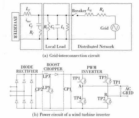
图2 分布式发电的逆变器互联系统原理示意Figure 2 Schematic circuits of the inverter-based DG interconnection system.
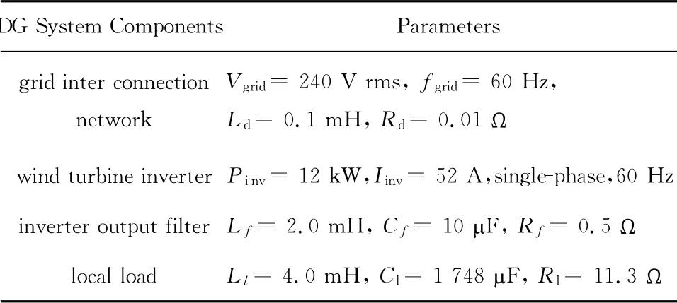
表1 分布式发电的逆变器并网参数Table 1 Parameters of DG inverter and grid interconnection
The breaker was opened at 0.5s,representing an islanding condition.Figure 3 shows that the APS algorithm failed to detect an islanding condition,a result of the balanced active power and reactive power between the DG and the local load.Figure 4 shows that the same islanding condition is detected by the AAPS algorithm.The probability of cause and effect is evaluated every 8 voltage cycles as an indicator of a hypothesized islanding condition.The PCE value increases dramatically after the islanding occurs and remains high as a result of the continuously additional phase shift.For testing purposes,the OFR/UFR tripping window is set at 59Hz/61Hz,a value much larger than practical power systems.Figure 3 and 4demonstrated the improvements of the proposed AAPS method in detecting islands over the traditional APS method.

图3 APS算法模拟反孤岛研究中失败实例(注意:在前几周模拟启动瞬变引起的突然相移可能没有被考虑)Figure 3 An example of failure of APS algorithm in simulated anti-islanding studies(Note:the abrupt phase shift in the first few cycles is caused by the simulation startup transients and may be disregarded)
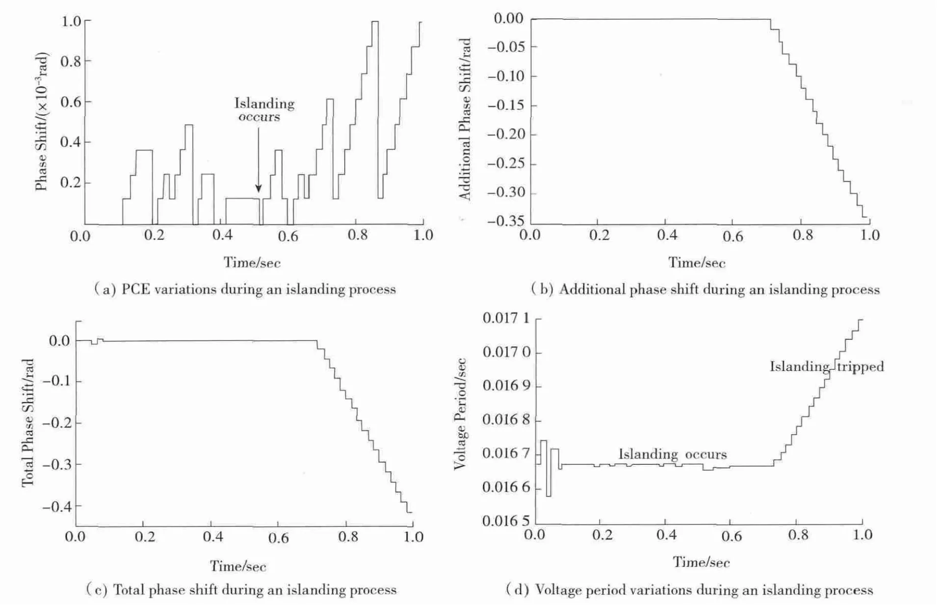
图4 成功的APPS反孤岛算法Figure 4 Successful anti-islanding action by AAPS algorithm
4 Testing for UL and CSA Certificatio
The developed AAPS anti-islanding algorithm has been integrated with commercial inverters for small wind turbines and photovoltaic systems[11],and has been certified against UL1741and CSA C22.2No.107.1-01standards[12-13]in compliance with grid interconnection requirements.The certification tests for UL1741(Inverters,Converters,Controllers and Interconnection System Equipment for Use with Distributed Energy Resources)and CSA C22.2No.107.1-01(General Use Power Supplies)were conducted based on IEEE 1547.1Standard for Interconnecting Distributed Resources with Electric Power Systems[14].The anti-islanding test configuration of a 12kW wind turbine inverter is shown in Figure 5 .
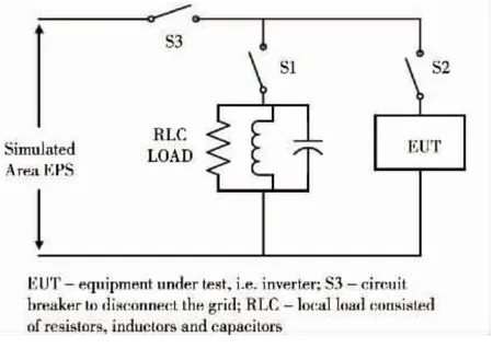
图5 反孤岛测试配置Figure 5 Anti-islanding test configuration.
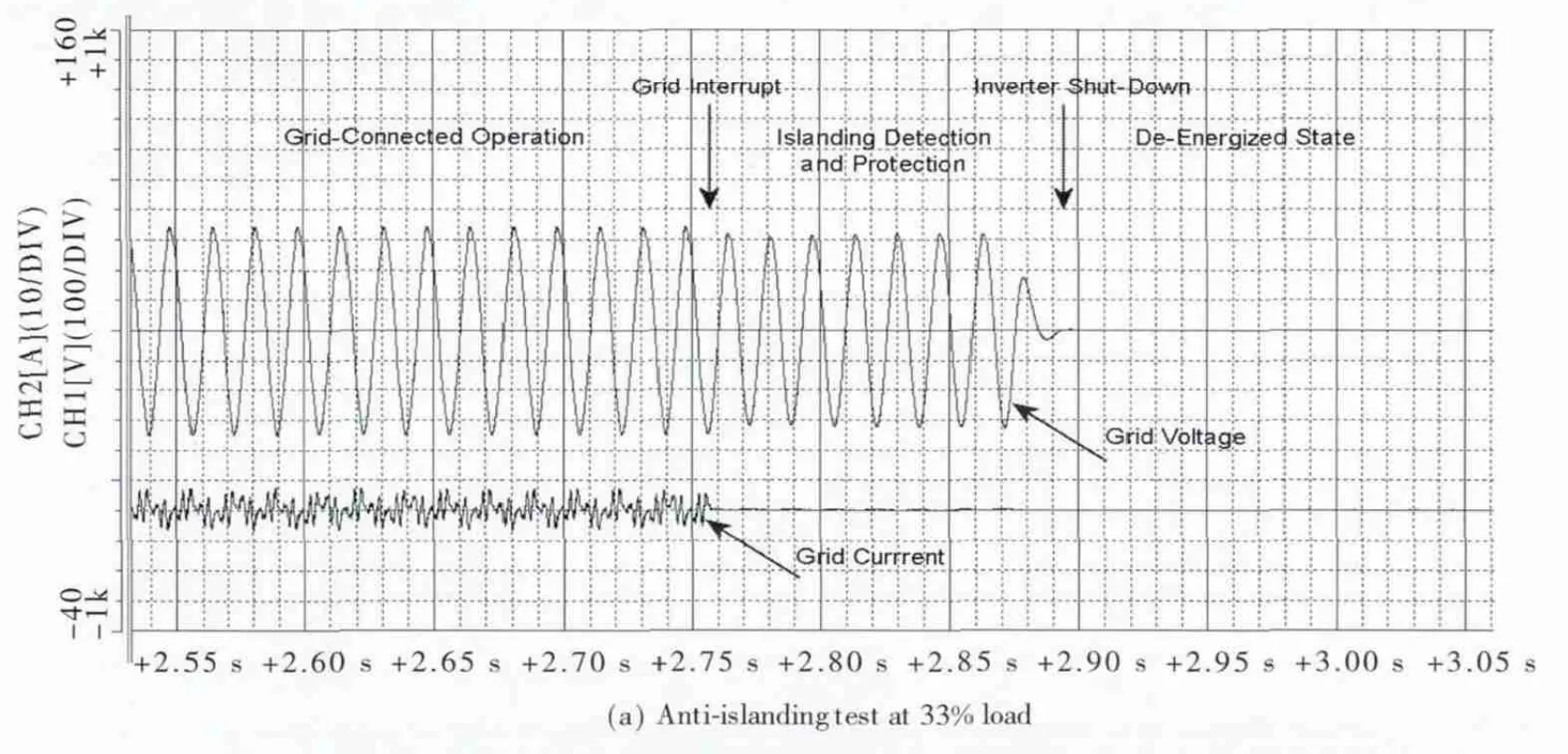
Under the rated and partial load conditions,the inductors and capacitors were adjusted to the resonant state,resulting in a minimum grid current.In this case the local load was supplied by the inverter even though the grid is still present.Circuit Breaker S3was then opened,disconnecting the grid and allowing the formation of an island.The islanding detection action of the AAPS algorithm was captured by the inverter output voltage and grid current waveforms,as in Figure 6 .The island was formed at the moment when the grid current dropped zero in Figure 6 .Then,the AAPS algorithm detected the formation of an island and de-energized the inverter,causing the inverter output voltage dropped to zero.The test conditions and results are summarized in Table 2 .Under the certification test conditions shown in Figure 6 ,it took the AAPS algorithm 181~268ms to deenergize the inverter,far less than 2.0sas required by grid interconnection standards.A total of 36anti-islanding certification tests were conducted under numerous operation conditions as specified by the IEEE interconnection standard[1,14],and have verified that the AAPS meet the anti-islanding requirement with a fast response and high reliability.

图6 局部和额定负载条件下的反孤岛测试波形(电网电压:100V/div;电网电流:10A/div)Figure 6 Anti-islanding test waveforms at partial and rated load conditions(grid voltage:100V/div;grid current:10A/div).

表2 参考UL/CSA标准APPS反孤岛测试条件及结果Table 2 Conditions and results of AAPS anti-islanding tests against UL/CSA standards
5 Conclusions
An accelerated automatic phase shift anti-islanding algorithm is presented in this paper along with the results of simulation and certification tests against grid interconnection standards.The simulation and test results have demonstrated that the AAPS method is an effective anti-islanding algorithm for inverter-based DG systems.The positive feedback process and the“cause and effect”logic of the AAPS algorithm results in a confirmation process for a hypothesized island and an accelerated addition of phase shift under a confirmed island,leading to a quick shut down of inverters in 100~300ms,far less than that required by gridinterconnection standards.The AAPS method has a very small phase shift in inverter’s output current when the DG system is connected to the grid,which gives little disturbance to the electrical power system and maintains a robust stability in inverter’s normal operation.The proposed anti-islanding algorithm has been applied to both singlephase and three-phase inverters for wind and small hydro DG systems,and the commercial singlephase inverters have been certified against UL and CSA grid interconnection standards.
[1]IEEE Standard 1547—2003,Standard for interconnecting distributed resources with electric power systems[S].
[2]Laaksonen H.Advanced islanding detection functionality for future electricity distribution networks[J].IEEE Transactions on Power Delivery,2013,28(4):2 056-2 064.
[3]Pukar Mahat,Zhe Chen,Birgitte Bak-Jensen.Review on islanding operation of distribution system with distributed generation[C].IEEE Power and Energy Society General Meeting,San Diego,USA,2011.
[4]Jun Yin,Diduch Chris P,Liuchen Chang.Islanding detection using proportional power spectral density[J].IEEE Transaction on Power Delivery,2008,23(2):776-784.
[5]Ning Liu,Aljankawey A S,Diduch C P,et al.A new impedance-based approach for passive islanding detection scheme[C].The 4th IEEE International Symposium on Power Electronics for Distributed Generation Systems,Rogers,USA,2013.
[6]Smith G A,Onions P A,Infield D G.Predicting islanding operation of grid connected PV inverters[J].IEE Proceedings Electtric Power Application,2000,147(1):1-6.
[7]Kern G A.SunSine300:Utility interactive ac module anti-islanding test results[C].26th IEEE Photovoltaic Specialists Conference,Anaheim,California,1997.
[8]Ropp M E,Begovic M,Rohatgi A.Analysis and per-formance assessment of the active frequency drift method of islanding prevention[J].IEEE Transations Energy Conversion,1999,14(3):810-816.
[9]Hung G,Chang C,Chen C.Automatic phase-shift method for islanding detection of grid-connected photovoltaic inverter[J].IEEE Transations Energy Conversion,2003,18(1):169-173.
[10]Jun Yin,Liuchen Chang,Chris Diduch.A new adaptive logic phase-shift algorithm for anti-islanding protections in inverter-based DG systems[C].IEEE Power Electronics Specialist Conference,Recife,Brazil,2005.
[11]Hossein Madadi Kojabadi,Bin Yu,Idris Gadoura,et al.A novel DSP-based current-controlled PWM strategy for single-phase grid connected inverters[J].IEEE Transactions on Power Electronics,2006,21(4):985-993.
[12]UL 1741—2010.Inverters,converters,controllers and interconnection system equipment for use with distributed energy resources[S].
[13]CSA C22.2No.107.1-01—2006.General use power supplies[S].
[14]IEEE Standard 1547.1-2005.Standard for conformance test procedures for equipment interconnecting distributed resources with electric power systems[S].
