Thrust Allocation with Dynamic Forbidden Sectors in Dynamic Positioning System
2014-01-19LIBoWANGLei
LI Bo,WANG Lei
(The State Key Laboratory of Ocean Engineering,Shanghai Jiao Tong University,Shanghai 200030,China)
Thrust Allocation with Dynamic Forbidden Sectors in Dynamic Positioning System
LI Bo,WANG Lei
(The State Key Laboratory of Ocean Engineering,Shanghai Jiao Tong University,Shanghai 200030,China)
Thrust allocation is one component of dynamic positioning system,which allocates the thrusts generated by the control law among the thrusters.Generally,forbidden sectors are set in thrust allocation to prevent thrusters from entering certain azimuth angles in order to avoid large thrust loss on downstream thrusters.In this paper,a novel concept of dynamic forbidden sector is proposed.Based on the results of model test,the extent of forbidden sector could be adjusted according to the propellers’speed ratio.This method could guarantee required safety.And numerical simulation indicates that thrust allocation could give more reasonable results after the introduction of dynamic forbidden sectors.
dynamic forbidden sector;dynamic positioning system;thruster-thruster interaction
1 Introduction
As the exploitation of gas and oil have been going into deep water,dynamic positioning(DP)system is a very essential part of a vessel or platform to maintain their horizontal positions for offshore operations.DP system measures the error between the actual and desired position of the vessel and generates forces through thrusters to counteract the environmental disturbances.As a typical dynamically positioned vessel has several thrusters,thrust allocation is used to allocate the commanded thrust generated by control law among the available thrusters.The thrust allocation method must minimize the fuel consumption of the thrusters and more importantly,the hydrodynamic interaction between azimuth thrusters should also be considered.When a thruster is in a neighboring thruster’s wake,its performance could be significantly reduced.As a result,the thruster may not generate the force we expect and the performance of the whole DP system would be harmed.Several reports are available to illuminate the phenomenon of thrust degradation due to the thruster-thruster interaction,such as Lehn(1980)[1]and Nienhuis(1992)[2].
In order to prevent the thruster-thruster interaction from reducing the performance of DP system,forbidden sectors are generally included in thrust allocation algorithms to forbid a thruster entering a sector where a neighboring thruster could be affected by its wake.Essentially,thrust allocation is an optimization problem.Several methods have been proposed and tested by many authors.A thorough survey of previously published methods for thrust allocation could be found in Fossen and Johansen(2006)[3].Typically,forbidden sectors are taken into acount in thrust allocation algorithm in two ways.The first one,as Serraris(2009)[4]described,is that the allocation problem is solved without forbidden sectors and if azimuth angles of any thrusters are orientated within the forbidden sector,the azimuth angle is fixed to its nearest boundary.In the second method,forbidden sectors are excluded from the feasible sectors for azimuth angles of thrusters.Consequently,forbidden sectors are dealt with as inequality constraints in the optimization problem directly.
Generally,forbidden sectors are considered as static zones which will not be changed once they have been determined.However,the propeller rotating speed of thrusters would be changing all the time during DP operation,so the degree of thruster-thruster interaction may not be the same.In order to establish more flexible feasible sectors for azimuth thrusters,a novel concept of dynamic forbidden sectors is proposed in the paper.According to the results of the experiment,forbidden sectors could be modified during the operation due to the rotation ratio of two neighboring thrusters without any cost of the performances of thrusters.Numerical simulation demonstrates that thrust allocation algorithm will give more reasonable results after dynamic forbidden sectors have been integrated into it.
2 Thruster-thruster interaction
In order to investigate the phenomenon of thruster-thruster interaction,a model test has been taken with azimuth thrusters.The main parameters of the thruster are listed in Tab.1.
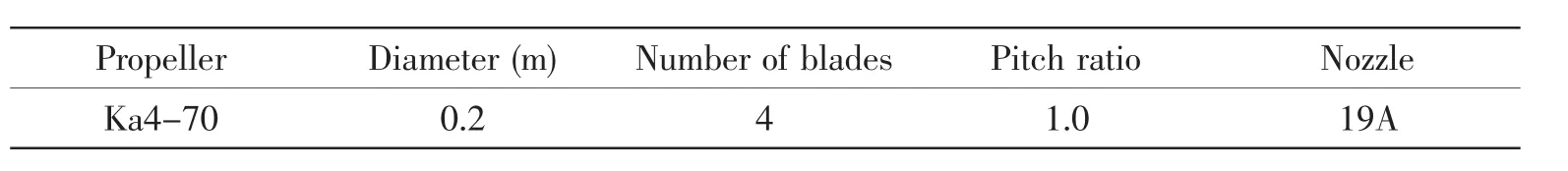
Tab.1 Main parameters of the azimuth thruster
2.1 Open water performance
The open water curves are displayed in Fig.1.KTPand KTdenote the thrust coefficients of the propeller and the whole thruster,respectively.
2.2 Thrust reduction due to the speed ratio of propellers
Two azimuth thrusters are placed in tandem condition in open water as showed in Fig.2 in the model test.
The distance between the two thrusters is 3D(D is the diameter of the propellers).The thrusts of the downstream thruster were measured and compared with the thrust on it when it was established in the flow alone.And this experiment also investigated the influence of dynamically positioned vessel’s drift velocity on the thrust reduction.The results of the experiment are showed in Fig.3.
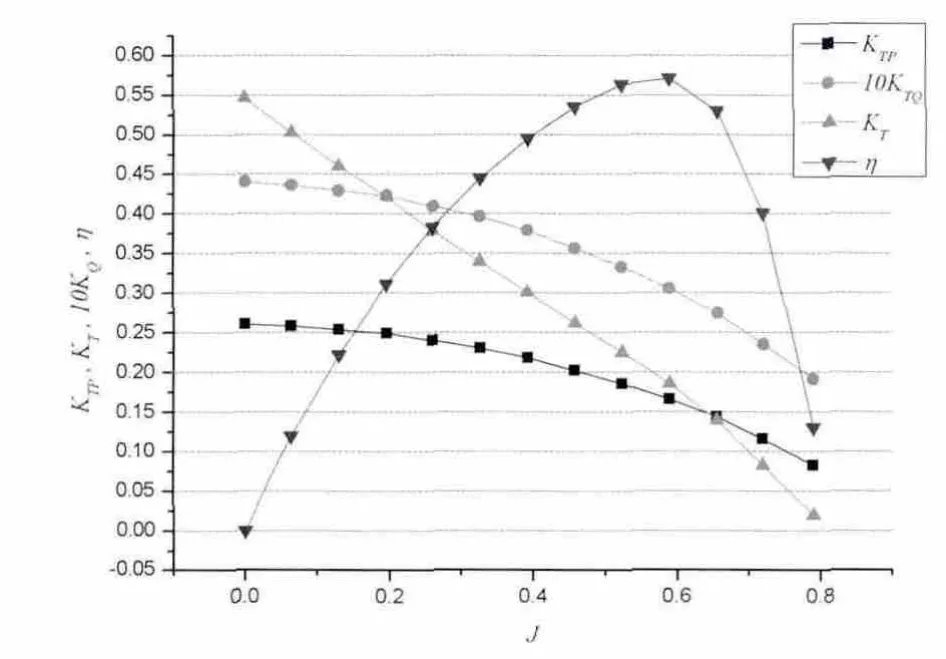
Fig.1 Open water performance of the azimuth thruster

Fig.2 Model test arrangement for thrusters in tandem condition

Fig.3 Thrust reduction due to the propellers’speed ratio and advance coefficient
According to Fig.3,thrust reduction for the downstream thruster and propellers’speed ratio could be viewed as linear relation.Besides,the thrust reduction is almost irrespective of the vessel’s drift,especially at low speed.
2.3 Thrust reduction due to the azimuth angle of forward thruster
The distance between the azimuth thrusters was adjusted to 7.64D.The azimuth angle of the forward thruster was steered to several different values to investigate their influence on the thrust reduction of the downstream thruster.The experiments were also conducted in several advance coefficients to study their effects.The experiments’setup is displayed in Fig.4.And Fig.5 shows the results of the experiment.
As seen from Fig.5,the azimuth angle of the forward thruster has a significant effect on the thrust reduction of the downstream thruster.As the increase of azimuth angle,the thrust reduction reduces.When the azimuth angle of the forward thruster is set to 9 degrees,the thrust reduction decreases to about 10%.The results demonstrate the necessity and effect of the establishment of forbidden sectors in thrust allocation methods.Besides,the advance coefficient seems to have little influence on the thrust reduction of the downstream thruster,especially when the inflow velocity is low.

Fig.4 Model test arrangement for thrusters with azimuth angles
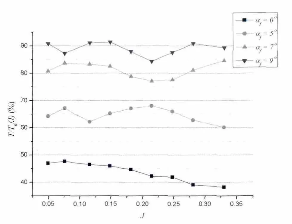
Fig.5 Thrust reduction due to azimuth angle of the forward thruster and advance coefficient
2.4 The relationship between speed ratio and forbidden sectors
With the results obtained above,we could establish the relationship between propellers’speed ratio and forbidden angles.Section 2.2 indicates that the relationship between downstream thruster’s thrust reduction and two propellers’ speed ratio could be assumed as linear.Due to the results in Section 2.3,we could also establish the relationship between forward thruster’s azimuth angle and thrust reduction of the downstream thruster.Taking the thrust reduction as a bridge,the forbidden sector of the forward thruster could be related to the propellers’speed ratio directly.The steps are indicated as follows.Firstly,similar to the formula proposed by Dang and Laheij(2004)[5],the relationship between forward thruster’s azimuth angle and downstream thruster’s thrust reduction could be described as the Eq.(1).

where t( αf)is the thrust reduction ratio when the azimuth angle of the forward thruster is αf,and c is a constant to be determined by the data from Section 2.3.The fitting curve and experiment data are displayed in Fig.6.
According to the results in Section 2.2,we can establish a linear function r( nf/ na)to describe the relationship between the thrust reduction and the propellers’speed ratio when the azimuth angle of the forward thruster is zero.Consequently,Eq.(1)could be rewritten as follows:

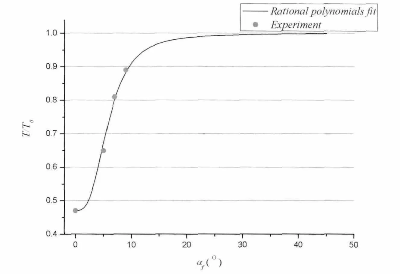
Fig.6 Thrust reduction under azimuth angles
The forbidden angle is the minimum azimuth angle of the forward thruster which could be set to avoid significant thrust loss of the downstream thruster.And it could be defined by the following expression:

where tcis the criterion value to determine forbidden angles,which is set to 0.98 in this paper.Combining Eq.(2)and(3),the forbidden angle could be expressed in the following equation.


Fig.7 The relationship between the forbidden angle and the speed ratio
Hence,we establish the relationship between the forbidden angle of the forward thruster and the two propellers’speed ratio.Eventually,we obtain Fig.7.
When nais zero which means the downstream thruster stops rotating for a period of time or fails,the forbidden angle of the forward thruster is set to zero.And in order to avoid very large forbidden angle,the maximum value of it is limited to 45°.
3 Thrust allocation strategy
An effective thrust allocation method is one of the key components in a DP system,because it determines whether the commanded thrusts generated by the control law could be allocated to the azimuth thrusters in a fast,reliable and fuel saving way.Generally,thrust allocation is a constrained optimization problem whose objective is to minimize power consumption.The constraints are usually to guarantee that the actual thrusts equal to the commanded ones and the azimuth angles of the forward thrusters are not in the forbidden sectors.However,some other factors should also be taken into accounts such as singular configurations(Sordalen,1997)[6],rate constraints on the azimuth angles and propeller speeds.A quasi-dynamic thrust allocation approach was proposed by Johansen,et al(2004)[7]which considered all the important factors.
3.1 Three degrees of freedom thrust allocation
In DP system,only three surface motions are considered,including surge,sway and yaw.The commanded force vector τ= (τX,τY,τN)T∈R3produced jointly by the azimuth thrusters is given by

The vector T∈Rmcontains the magnitude of the force generated by each individual thruster.The angle αiis the azimuth angle of the i-th thruster,and the vector α∈Rmcontains all these angles.The i-th column of the 3×m matrix B(α) is given by
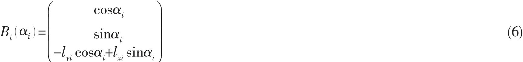
The coordinates of the i-th thruster in the horizontal plane is (lxi, lyi)in the coordinate system with origin in the center of gravity,positive x-axis forward,and positive y-axis toward port.A singular configuration is characterized by B(α ) not having full rank,which means that the actual force B(α ) T is restricted to a subspace of R3so that the commanded force cannot be attained.
3.2 Quasi-Dynamic thrust allocation approach
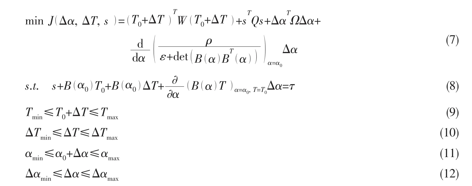
In Johansen,et al(2004)[7],the following optimization problem is defined at each sampling instant in real time.T0and α0are thrusts and azimuth angles of the thrusters at the prior sampling time.The total power consumption is estimated by the first term in Eq.(7)where W∈Rm×mis the weight matrix.The second term sTQs penalizes the errors between the commanded and actual force.The slack variable s is necessary in order to guarantee that the optimization problem always has a feasible solution(see Eq.(8)).The weight matrix Q should be very large.The rate-of-change in azimuth angles is minimized by the third term with a weight matrix Ω in Eq.(7).The last term guarantees that singularity configuration should be avoided,where ε>0 is required to avoid numerical problems and ρ>0 is a weighting parameter.Eqs.(9)-(12)define the limitations of individual thruster’s thrust and azimuth angle(forbidden sector)and rate constraint of them as well.These kinds of constraints that represent the physical limits of a thruster could be described by the concept of dynamic thrust region which is showed in Fig.8.
The optimization problem proposed above is a locally convex quadratic programming which could be readily solved.
3.3 Dynamic forbidden sectors
Forbidden sectors for azimuth angles are considered in Eq.(11)by defining a limitation[αmin,αmax]on α.Due to the results of Part 2,the boundary of a forbidden sector could be adjusted according to the propellers’speed ratio without any cost of the thrust on the downstream thruster.Consequently,Eq.(11)could be rewritten as follows:

Fig.8 A dynamic thrust region

4 Numerical simulation
Numerical simulations of a barge-shaped vessel equipped with a DP system which is in-tegrated with dynamic forbidden sectors are conducted in order to investigate the effect of dynamic forbidden sectors on the performance of thrust allocation and the entire DP system.The main parameters of the vessel are listed in Tab.2.

Tab.2 Main Dimensions of the vessel
The control law of DP system is PID controller whose coefficients are determined by trial and error.The low-frequent motions of the vessel are obtained through model-based passive nonlinear observer(Fossen and Strand,1999)[8].
The vessel is equipped with six azimuth thrusters(see Fig.9).The details of the arrangements of the thruster and the shapes of feasible sectors for azimuth angles are indicated in Fig.10.The diameter of the propellers is 3.6 m and the maximum thrust they can deliver is 800 kN.As we can see in Fig.10,the feasible azimuth sectors of Thruster No.1 are divided by the existence of forbidden sectors into two parts,Sector A and Sector B.The interaction between Thrusters No.6 and No.2 is neglected,as well as Thrusters No.5 and No.3.

Fig.9 The vessel with azimuth thrusters

Fig.10 Arrangements of the azimuth thrusters
The DP system is simulated under only wave disturbances.The irregular waves are generated due to JONSWAP spectrum whose significant height is 5.27 m and peak period is 13.4 s with peak shape parameter 3.3.The numerical simulation is conducted on the program based on Matlab/Simulink.Each case is simulated for 3.5 hours of which the first 0.5 hour was excluded from the final analysis.An overview of the simulation cases is in Tab.3.

Tab.3 Simulation cases
5 Results
The results of the simulations are listed below.Because the differences of the vessel’s position and heading between the cases with and without dynamic forbidden sectors are rather small,no results about the position and heading are reported here.The power used by the thrusters is represented by ΣT2(t).

Tab.4 Results of thrust
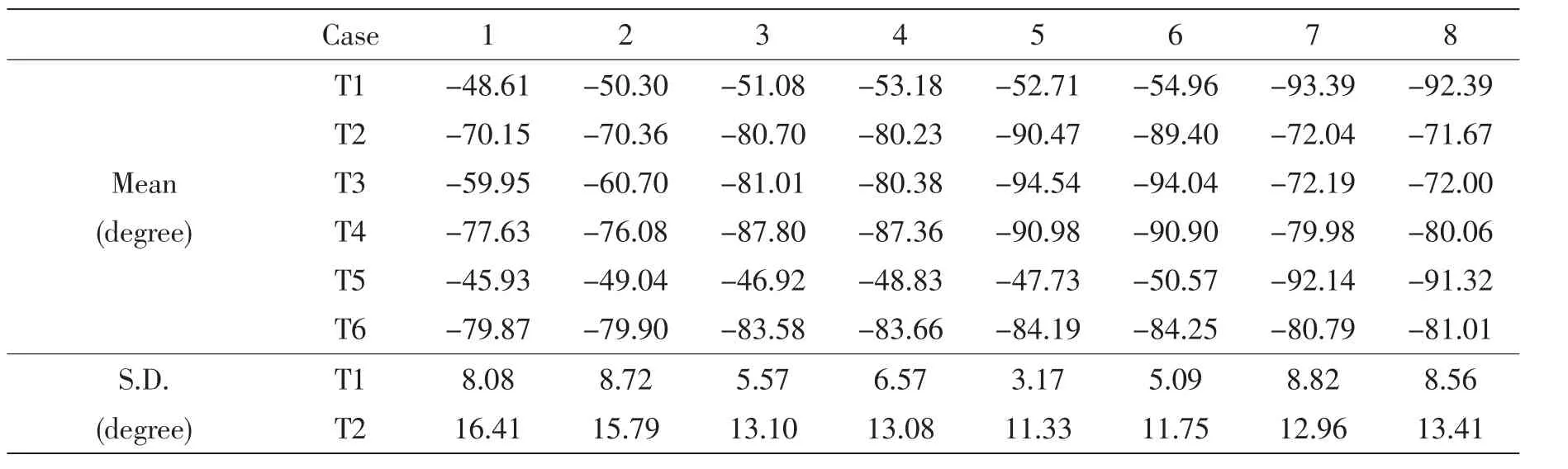
Tab.5 Results of azimuth angles

Continue Tab.5

Tab.6 Relative change of power due to dynamic forbidden sectors
Tabs.4 and 6 demonstrate the effect of dynamic forbidden sectors on the thrust of the azimuth thrusters.After the introduction of dynamic forbidden sectors,mean thrust on the azimuth thrusters changes very slightly.But it is worth noticing that Thrusters No.1 and No.5’s thrust always increases with dynamic forbidden sectors,which means that with larger feasible azimuth angles the thrust allocation algorithm tends to allocate more thrust on them.The tendency is more obvious in Tab.6 which presents the total power of the thrusters.In the case of 130°incoming waves,the introduction of dynamic forbidden sectors makes the allocation algorithm allocate more thrust on Thrusters No.1 and 2,which is what we desire because more moment to counteract the waves could be obtained.At the same time,the thrust on some other thrusters decreases as well as the total one.The thrust allocation method could give more satisfactory results when some thrusters have larger feasible angle zones.Other cases could yield the same conclusions.
In cases 7 and 8,the azimuth angles of Thrusters No.1 and 5 are set to Sector B instead of Sector A.With the incoming waves at 110°,it seems reasonable that azimuth angles in Sector B are a better choice because their direction could be just opposite to the wave direction.As we expect,dynamic forbidden sectors make little difference when azimuth angles in Sector B.Even with larger feasible angle sectors,there is no need for allocation algorithm to place the thruster into the former forbidden sectors(see Tab.5).And Tab.6 indicates the great difference in power with azimuth angles in more proper positions.
6 Conclusions
Based on the results of model test,the concept of dynamic forbidden sectors for azimuth thrusters is proposed in this paper.It is demonstrated that the forbidden sectors are not necessarily static as formerly considered.They could change due to the ratio of two propellers’speed.The adjustment of forbidden sectors has several advantages.First,if the speed ratio of two propellers increases which indicates larger thruster-thruster interaction,the forbidden sectors will be enlarged so that significant thrust loss could be avoided and better performance of DP system could be guaranteed.Second,when the degree of interaction decreases,the size of forbidden sectors will also be smaller.And given larger feasible azimuth zones,thrust allocation algorithm could give better allocation scheme among the thrusters.It is also important to place the azimuth angle into a suitable feasible sector at the first place,because the azimuth angle cannot cross the whole forbidden sector into other feasible ones.
[1]Lehn E.Thruster interaction effects[R].Ship Research Institute of Norway,Marine Technology Center.NSFI Report-120.1980:1-22.
[2]Nienhuis U.Analysis of thruster effectivity for dynamic positioning and low speed manoeuvring[D].Dissertation of Technical University Delft,1992.
[3]Fossen T I,Johansen T A.A survey of control allocation methods for ships and underwater vehicles[C]//In 14th IEE Mediterranean Conference on Control and Automation,June 2006.Ancona,Italy,2006.
[4]Serraris J J.Time domain analysis for DP simulations[C].ASME Conference Proceedings,2009(43413):595-605.
[5]Dang J,Laheij H.Hydrodynamic aspects of steerable thrusters[C].Dynamic Positioning Conference,2004.
[6]Sørdalen O.Optimal thrust allocation for marine vessels[J].Control Engineering Practice,1997,5(9):1223-1231.
[7]Johansen T A,Fossen T I,Berge S P.Constrained nonlinear control allocation with singularity avoidance using sequential quadratic programming[J].Control Systems Technology,IEEE Transactions on,2004,12(1):211-216.
[8]Fossen T,Strand J.Passive nonlinear observer design for ships using Lyapunov methods:Full-scale experiments with a supple vessel[J].Automatica AUT,1999,35(1):3-16.
采用动态禁止角的动力定位系统推力分配策略
李 博,王 磊
(上海交通大学 海洋工程国家重点实验室,上海200030)
动力定位系统利用推力分配策略将总推力需求分配到多个推进器上。为了避免由推进器尾流造成的推进器之间的水动力干扰,通常会在推力分配策略中设置推进器回转方向的禁止角。全回转推进器水动力干扰试验的结果显示,推进器之间水动力干扰的程度前后随推进器的相对转速而变化。以模型试验的数据为基础,文章首次提出了动态禁止角的概念和数学模型。通过在推力分配策略中设置动态禁止角,回转方向的禁止角将随推进器的相对转速变化而进行调整,从而完全避免推进器之间的水动力干扰问题。动力定位系统的数值模拟结果显示新的推力分配策略可以给出更合理的分配结果。
动态禁止角;动力定位系统;推进器水动力干扰
U661.31+3
A
李 博(1987-),男,硕士生;
王 磊(1971-),男,上海交通大学副教授。
U661.31+3
A
10.3969/j.issn.1007-7294.2014.09.002
1007-7294(2014)09-1024-11
date:2014-06-13
Supported by National Natural Science Foundation of China(Grant No.51179103)
Biography:LI Bo(1987-),male,master of Shanghai Jiao Tong University,E-mail:lither0627@gmail.com;
WANG Lei(1971-),male,associate professor,E-mail:wanglei@sjtu.edu.cn.
猜你喜欢
杂志排行
船舶力学的其它文章
- A Rule of Spatial Sampling on Cylindrical Shells for Predicting Radiated Acoustic Field
- Vessel Motion Effects on Nonlinear Dynamics of Deepwater Drilling Riser
- Investigation on Sloshing Effects of Tank Liquid on the FLNG Vessel Responses in Frequency Domain
- Effect of Plastic Zone Size Induced by a Single Dwell Overload on the Fatigue Crack Growth Rate under Cyclic Loading
- Research of Vertical Bending Moment in Amidships Calculation Method Caused by the Crash-breaking Way
- Study of Vortex Induced Characteristics of Multi-columns with Low Mass Ratio