Design and Simulation for Controlling Automatic Clutch System by Fuzzy Logic
2013-12-07LIXinYANGXinhuaYEMingCAOLuzheng
LI Xin, YANG Xinhua,YE Ming, CAO Luzheng
1.a.Chongqing Institute of Automobile;b. Key Laboratory of Manufacture and Test Techniques for Automobile Parts, Ministry of Education,Chongqing University of Technology,Chongqing 400054, China;2.Chongqing Academy of Science and Technology, Chongqing 401123, China
DesignandSimulationforControllingAutomaticClutchSystembyFuzzyLogic
LI Xin1a,2*, YANG Xinhua1a,YE Ming1b,2, CAO Luzheng1a
1.a.ChongqingInstituteofAutomobile;b.KeyLaboratoryofManufactureandTestTechniquesforAutomobileParts,MinistryofEducation,ChongqingUniversityofTechnology,Chongqing400054,China;2.ChongqingAcademyofScienceandTechnology,Chongqing401123,China
Theelectro-mechanicalcontinuouslyvariabletransmissions(EM-CVT)representanareaofgreatindustrialinterestthatisobtainedmuchoftheattentionallovertheworld.TheautomaticclutchcontrolisacoretechnologyforthedevelopmentofEM-CVT.ThepaperpresentsanewcontrolstrategytotheautomaticclutchofanEM-CVTusingtherulesoffuzzylogic.Theclutchsystemmodelingwasconstructedincludingclutchmechanismmodel,clutchtransmissionmodel,andinternalcombustionenginemodel.MATLAB/Simulinksimulationisperformedtovalidatethefuzzylogiccontrolperformanceoftheautomaticclutchunderdifferentoperatingmodes,comprisingstartinguponflatandhill-startroads.TheproposedapproachdevelopsareasonablereferencefordesigntheautomaticclutchoftheEM-CVT.
electro-mechanicalcontrol,automaticclutchsystem,fuzzylogic,simulation
1.Preface
The Automatic Clutch System (ACS) is a new clutch control device of vehicle, which is independent on the automatic transmission. By automatic controlling the traditional dry clutch, ACS can obtain the driving effect that is similar with the function of electronically controlled Automatic Mechanical Transmission (AMT). Recently, this kind of control device is just installed on a few vehicles out of the factory, and it may be chosen to assemble based on the manual transmission by some car owners. Overall, the ACS which is paid a little attention on is not widespread use in the automobile field.
With the rapid development of the Continuously Variable Transmission (CVT)[1-2], the control method has been developed very much from the early mechanical control, mechanical hydraulic control, to the widely used electro-hydraulic control. CVT has a unique advantage that can change the speed ratio at the same time without interrupting the torque transmission. Currently, a new type of electro-mechanical control of CVT (EM-CVT), which depends on the disc spring pressure to ensure the clamping force of the pulleys, is presented. The pulleys movement can be controlled by the speed control system, which mainly comprises the motor, the reduction gear, the executing agency, the sensors and the electronic control unit. Since there is no hydraulic system, the efficiency of this new type CVT transmission can be increased more than 10% compared with electro-hydraulic control. Therefore, the EM-CVT is likely to be the direction of the development of next-generation CVT.
In order to obtain the clamping force of the pulleys, the disc spring is used. Simplistically, the control of clamping force can be ignored. Thus, there are only two control purposes of the EM-CVT shown as: automatic clutch control for vehicle start, and the EM-CVT speed control system control issues. The new CVT has expanded the scope of the application of the automatic clutch, and also provides the possibility of large-scale usage of the automatic clutch.
The paper focuses on the development of the control strategy for electronically controlled automatic clutch. The rationality and feasibility of the control system is validated by the simulation results. The proposed approach can be used as an important component of the EM-CVT overall control strategy.
2.The Basic Structure df the Automatic clutch system
The electronically controlled automatic clutch includes the motor, the clutch control mechanism, the controller and various sensors. The structural principle of the ACS is shown in Figure 1: the motor rotation speed is decreased by the worm gear reducer, and then, the displacement of lasso makes the clutch shift fork rotate around a fixed fulcrum, which will drive the clutch sleeve to move. Fig.1 is the tension of the lasso where the clutch is in separating state (assuming that the motor rotation direction is positive). When the motor is reversed, the lasso moves to the right side, and the big end of the diaphragm spring which is under the spring action pushes the release bearing move to the left side, meanwhile driven disc is pressed to the flywheel.
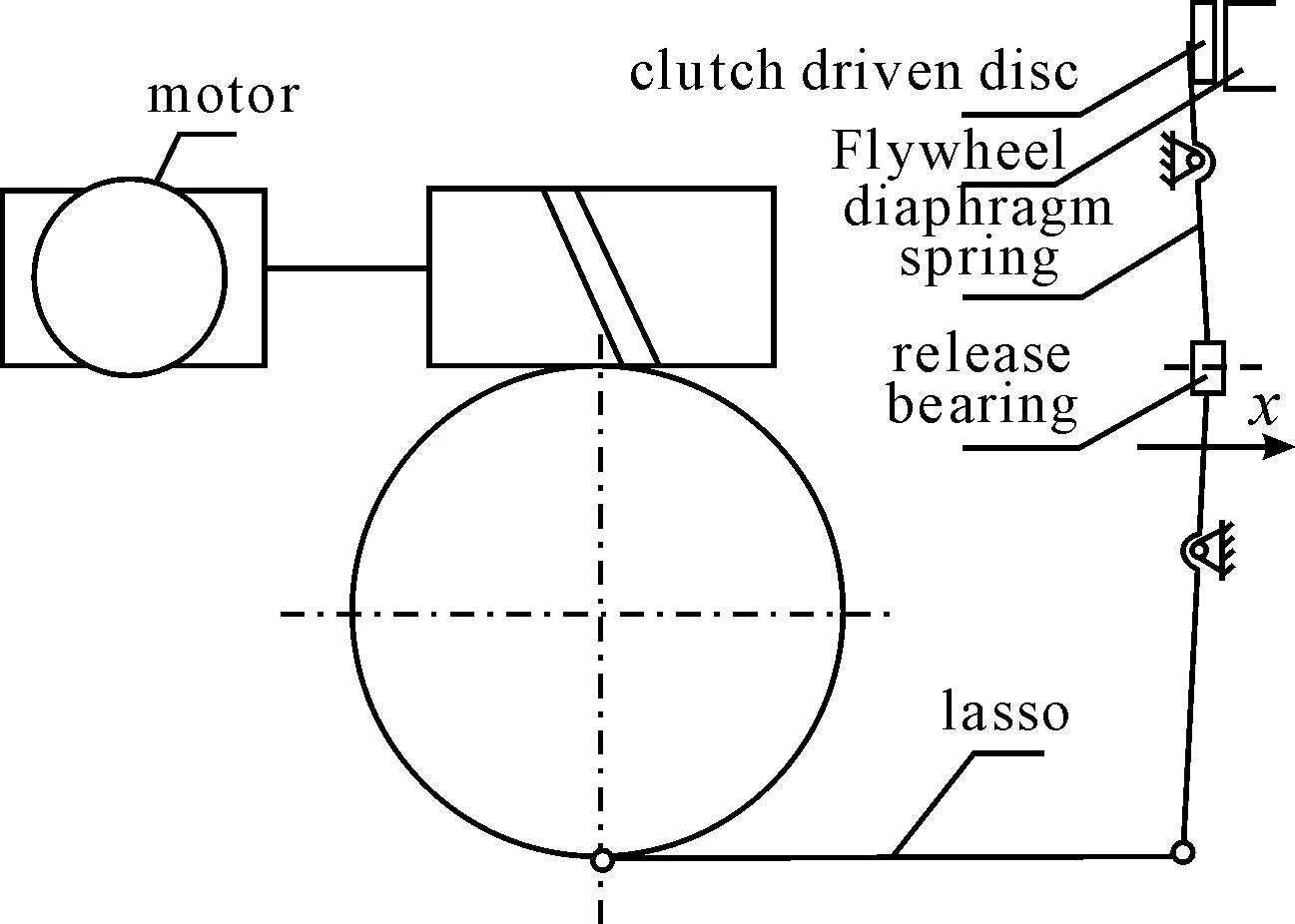
Fig.1 The basic structure of the automatic clutch system
The controller needs to collect the following information: the internal combustion engine throttle opening, the internal combustion engine speed, the speed (or continuously variable transmission output shaft rotational speed), the brake pedal signal, and the automatic clutch worm gear output angle signal. Since most of the signals can get from the Vehicle Controller Unit (VCU), the angular displacement sensor whose output angle signal will be provided to the system is installed in the worm reduction gear. The role of this angle signal is to control the motor trip and ensure the joint speed of the driven disc.
3.Control system mathematical model
3.1.Clutchcontrolmechanismmodel
Assumption: the displacement of the clutch big end is x, the anti-drag torque is generated by the motor through the worm reduction gear lasso. Due to the role of self-locking worm, the torque cannot pass to the motor, while the motor rotates after overcoming the static torque to drive the worm and the worm gear rotation, making the length of the lasso changes, and the variation equals to the angle of worm rotation multiplying the radius of gyration.
(1)
If ignoring the control mechanism of elastic deformation, the amount of movement of the clutch discx′ is:
x′=x·i3
(2)
3.2.Motormodel
The DC motor is selected as a power source for control mechanism of the electronically controlled automatic clutch, whose rated power is 120 W, rated voltage is 12 V, and rated speed is 3 000 r/min, respectively. Combining Kinetic equation with the DC motor and Voltage balance equation, the paper establishes a mathematical model of the motor[3] as follows:
(3)

3.3.Simplifiedmodeloftheclutch
According to the dynamics of clutch, internal combustion engine-the clutch-body model is simplified as shown in Fig.2.

Fig.2 simplified model of “internal combustion engine-the clutch-body”
When the clutch slipping in the bonding process stage (ne>nv), the kinetic equation expressions are as follows:
(4)
where:Tvis the sum of the moment of inertia which clutch driven disc to the wheel and the equivalent of body. When the clutch is fully engaged, the kinetic equation is expressed as follows:
(5)
3.4.Themodelofclutchtransmissiontorque
The electronically controlled automatic clutch applies DC motor to drive mechanical reduction mechanism to control the movement of the clutch engagement sleeve. Therefore, using the method described in the literature to establish the mathematical model of the electronically controlled automatic clutch transmission torque is obtained as follows:
(6)
where,Tcis clutch transmission torque,zis the number of frictional contact surface,Fis the normal pressure which can be simplified by the diaphragm spring characteristics in accordance with the third-order curve fitting,μcis dynamic friction coefficient of the friction plate,D1is the outer diameter of friction plate,Dis the diameter of friction plate.
3.5.Vehiclemodel
According to the traffic equation, the moment of resistance of vehicle tires during driving can be developed as:
(7)
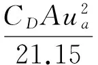
where,i0is the main drive ratio,fis the coefficient of rolling resistance,Gis the gross vehicle weight,αis the slope angle,CDis the drag coefficient,Ais the frontal area,uais the speed.
3.6.Combustionmodels
“我们家的草灰鸭蛋就摆在展示中心展销,我们的客户大多来自铜陵市,在此之前,几乎没有人知道永兴村有这么好的粽子和鸭蛋。”周兴祥说,永兴村的特色农产品是糯稻,村民更是爱包手工粽子。虽然手工粽子品质较好,但由于位置偏僻,以前很少有人主动前来收购。
Since the internal combustion engine output torque, power output and fuel consumption are affected by the throttle opening, speed, ignition advance angle and other factors, it is hard to construct a precise and complete internal combustion engine mathematical model. Based on the internal combustion engine speed characteristic test data only, this paper considers the impact of the throttle and speed of these two factors on the internal combustion engine output torque and fuel consumption. The simplification is suitable for the simulation requirements, which are validated by the practical applications[4].
4.The control strategy of the automatic clutch system
4.1.Analysisoftheclutchengagementprocess
The clutch engagement process is shown in Fig.3. The process will be divided into four stages (some literature divide it into three stages[5-6]): 0 to Δ is the time for idle running of the clutch, during which driven disc is jointed with the flywheel disk, Δ tot1time period is the preparation stage of the clutch engagement, where clutch transmission torque is increased from zero, until the moment of resistance is overcome, the clutch driven disc starts rotating,t1tot2time periods is for the clutch slipping phase, where the clutch disc is in sliding friction state and the clutch disc speedωcis less than the internal combustion engine flywheel speedωe, aftert2, the clutch is fully engaged, where the flywheel and the driven disc are synchronous rotating.
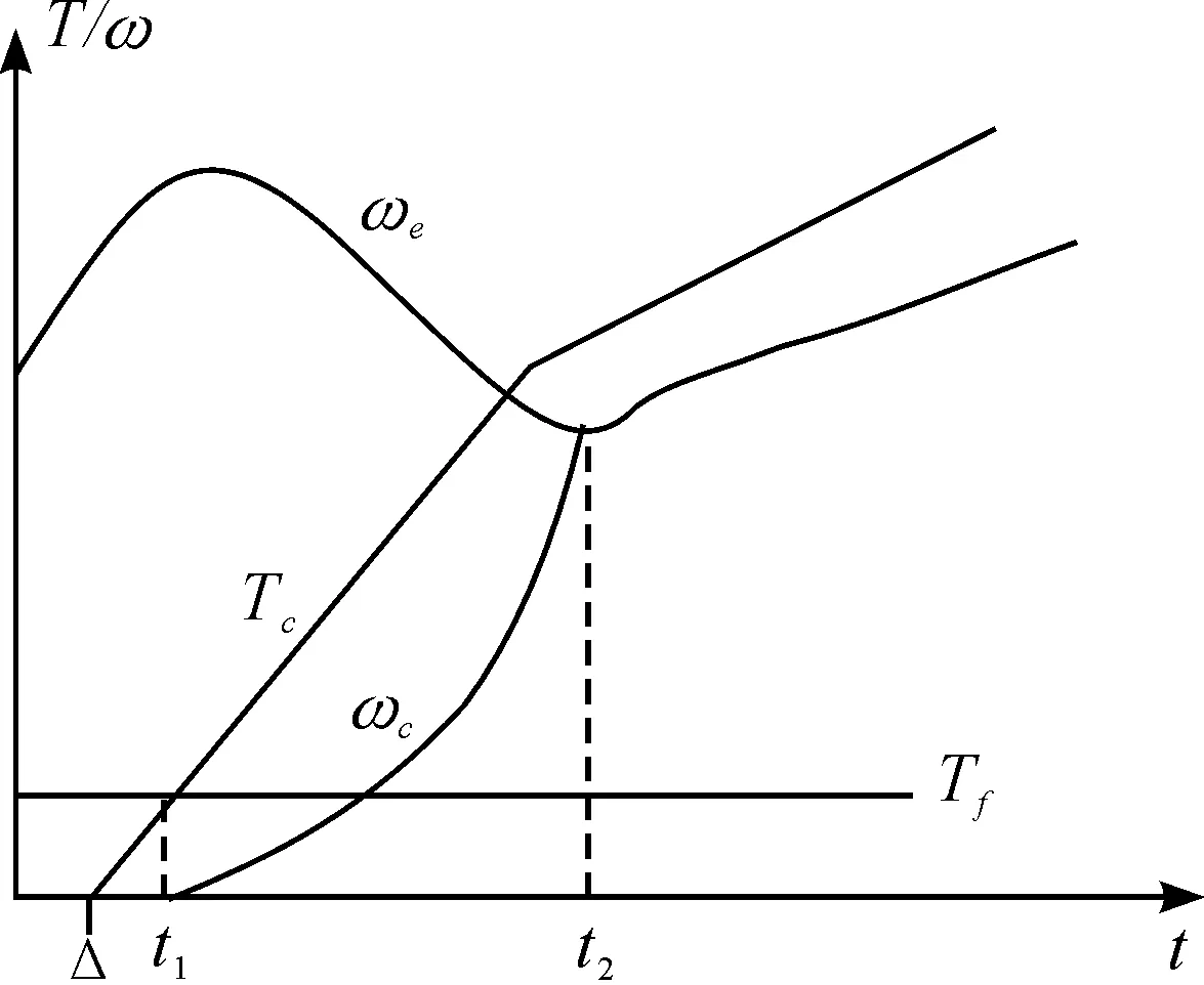
Fig.3 Clutch engagement process schematic
4.2.Thecontrolstrategyoftheautomaticclut-chsystem
When vehicle is starting, the judgment of electronically controlled automatic clutch engagement is: switching the CVT gear from neutral or parking to forward gear or reverse gear; no brake signal. The DC motor begins to rotate, while the drive worm and worm gear rotating. According to the feedback signal of the angular displacement sensor, the clutch releases the lasso until the electronically controlled automatic clutch reaches the semi-bonding position. It will prevent the vehicle from slipping when it starts at the ramp. Then, based on the throttle opening, the clutch will determine the driver’s intention and confirm the working conditions.
In the idle running of the electronically controlled automatic the clutch, DC motor armature voltage is the maximum that can minimize the time of the driven disc after idle running time Δ, to not only make it faster to enter the joint preparation phase, but also ensure that the electronically controlled automatic clutch engagement performance is not affected. Therefore, in the stage of idle running, the DC motor armature voltage maintains rated voltage value (12 V). And the driven disc is at the semi-joint position that is the end of idle running. If the driver does not release the brake pedal, the DC motor armature voltage is zero and the motor stops rotating, while electronically controlled automatic clutch is keeping a semi-bonding state.
For the electronically controlled automatic clutch engagement of the preparation phase and the friction stage, the paper uses the vague language to describe the relation of the input and output as follows:
Internal combustion engine throttle opening degreeα:{tiny, small, medium, large},speed difference between the internal combustion engine flywheel and the electronically controlled automatic clutch driven disc Δn:{large, medium, small},DC motor armature voltageU:{tiny, small, medium, large}.
Using fuzzy logic control toolbox of SIMULINK to build fuzzy control module of electronically controlled automatic clutch, membership functions and control rules are selected based on trials and errors, which can be adjusted and modified according to the simulation and experimental results.
To ensure that the electronically controlled automatic clutch engagement speed varies with the bonding degree of change varies, DC motor armature voltage Uis determined by the internal combustion engine throttle openingαand the difference of the rotary speed Δnbetween the flywheel and the driven disc, where the speed difference of the rotary speed Δnis used for the correction of the armature voltageU. Fuzzy control rules of DC armature voltage are developed on the basis of the above control strategy as shown in Tab.1.
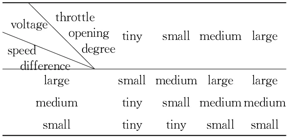
Tab.1 DC armature voltage fuzzy control rule
5.The simulation results
5.1.Simulationresultsandanalysisofthestartconditionsofflatroad
The driver manipulation: at 0.5 s, CVT is hanged on forward gear, while releasing the handbrake (or releasing the brake pedal); at 1 second, throttle is opened to pre-set target; Figure 4 shows the simulation results of 20% and 80% throttle opening degree. It can be seen from Fig. 4: the control effects of electronically controlled automatic clutch matches the control requirements when throttle opening degree is small, and the electronically controlled automatic clutch engagement time is longer, otherwise the bonding time is less than 2 s.
5.2.Simulationresultsandanalysisofthehill-startconditions
Choosing hill-start for the larger slope of the start conditions, the feasibility of the simulation electronically controlled automatic clutch control strategy is validated based on the start condition of 10% slope. Comparing with ground starting, the hill-start should ensure that vehicles are not starting with slip.
Driver manipulation methods: CVT was hanged on forward gears at 0.5 s; at 1 s, releasing the handbrake (or releasing the brake pedal); comparing 20% with 80% throttle opening degree, the simulation results are shown in Fig.5. From the figure, it can be seen that: in reference to the slope of the start conditions of the vehicle 20% throttle position conditions, the internal combustion engine will be a long time staying at a low speed, where the limit of the state may lead to turn off the internal combustion engine machine. In this case, the driver will usually increase the throttle position. At the same time, it can also be seen that: in ramp starting situation, if the throttle opening degree is small, electronically controlled automatic clutch engagement time will be longer than 2.6 s, which would lead to a big friction work and make a larger wear. But, the mechanical shock generated by the combination of the flywheel and the driven disc is small.

Fig.4 Simulation results for different throttle position at start conditions of flat road
Comparing with the simulation results of the proposed two kinds of starting conditions, the paper obtain: in the hill-start conditions, although the start time of the vehicle is lagging behind, the electronically controlled automatic clutch control strategy this paper developed can still meet the use of vehicles and ensure that there is no slip at the starting.
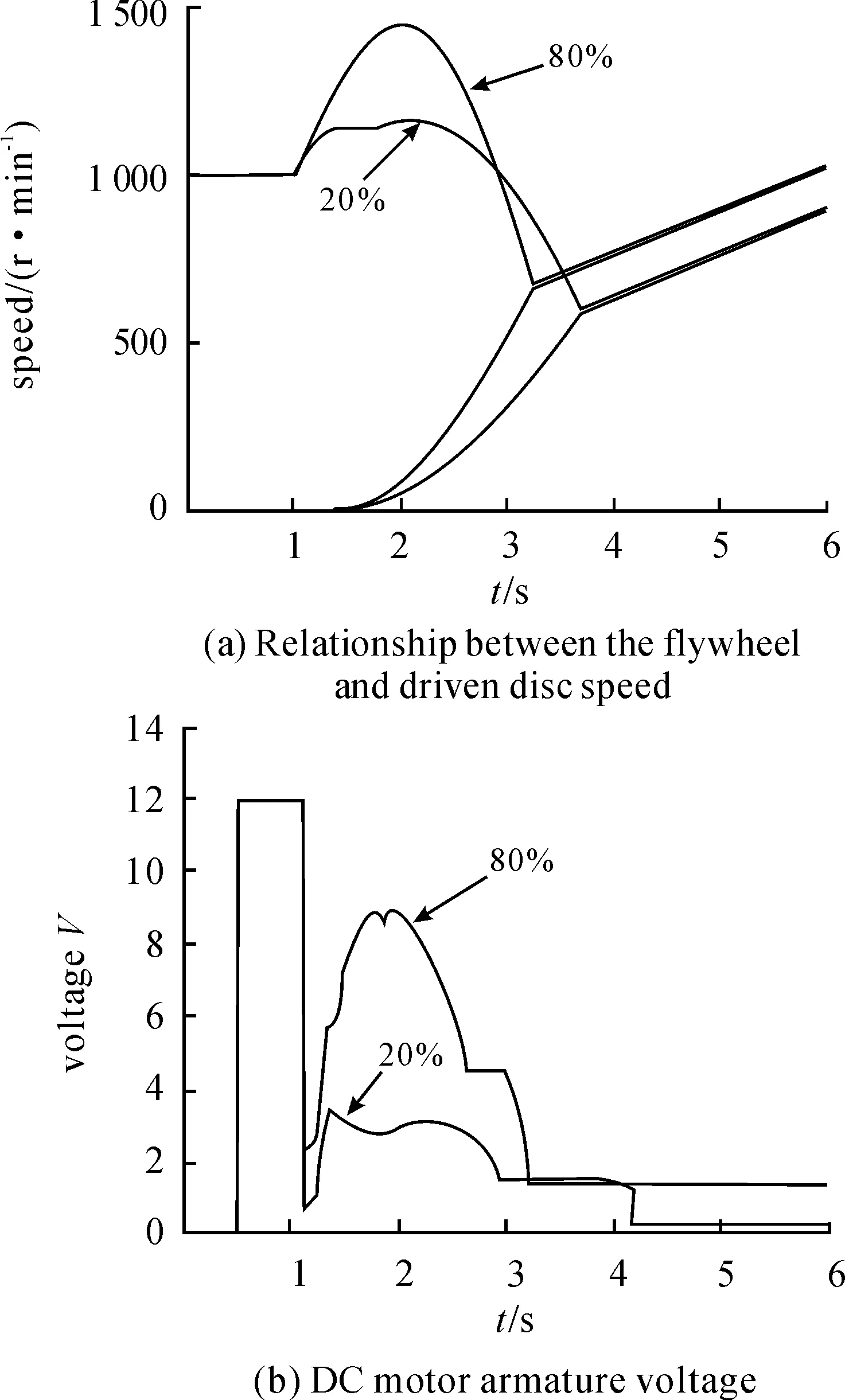
Fig.5 Simulation results for different throttle opening degree at ramp start conditions
5.3.Simulationofemergencystartworkingcondition
In order to research the reaction of electronically controlled automatic clutch when vehicles in an emergency start condition, two conditions are set for simulation comparison as shown in Fig. 6. The first one is the throttle opening degree is added from 0 to 100% in a very short time; the second type is the normal starting conditions, i.e., the driver added throttle opening degree from 0 to 30%. From the figure, it can be obtained: at the emergency starting condition, the electronically controlled automatic clutch engagement time is about 2 second, meanwhile it is found that the vehicle has an larger acceleration at the starting of an emergency.
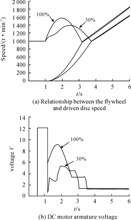
Fig.6 Simulation of emergency start condition and normal starting conditions
6.Conclusions
In this paper, the control strategy of electronically controlled automatic clutch is developed. According to the basic control strategy, to make the electronically controlled automatic clutch engagement speed (DC armature voltage) can match the driven disc location (difference of the rotary speed) and driver′s manipulation of intent (throttle opening degree) variations, a fuzzy logic control rule is proposed, and an electronically controlled automatic clutch simulation model is constructed by SIMULINK.
Combining common flat road start, hill-start and emergency start working conditions, the results verify the rationality and feasibility of the proposed electronically controlled automatic clutch control strategy. The paper provides a more reliable theoretical basis and design reference for design of automatic clutch.
[1] SAE Design Guedeline: Metal Belt Drive Continuously Variable Ratio (CVT) Automatic Transmissions[Z].SAE J2525,2000.
[2] YANG Xinhua,CHENG Naishi, LI Zhaohui. Electro-Mechanical Control Devices for Continuously Variable Transmissions[Z].2008 SAE International Powertrains, Fuels and Lubricants Congress.SAE 2008-01-1687. 2008.
[3] HUANG Lipei. motor control[M].Beijing:Tsinghua University Press,2003.
[4] Michael Henry Smith.Vehicle Powertrain Modeling and Ratio Optimization for a Continuously Variable Transmission[D].Georgia: Georgia Institute of Technology,1998.
[5] HU Jianjun,LI Guanghui,WU Guoqiang,et al.Accurate calculation analysis of the car started the process of clutch transmission torque[J].Automotive Engineering,2008,30(12):1083-1086.
[6] ZHANG Feitie,ZHOU Yunshan,XUE Dianlun.CVT start clutch Control Algorithm[J].Journal of Hunan University:Natural Science Edition,2006,33(6):57-60.
基于模糊逻辑的自动离合器控制策略设计与仿真
李 鑫1a,2*,杨新桦1a,叶 明1b,2,曹鲁政1a
1.重庆理工大学 a.重庆汽车学院;b.汽车零部件制造及检测技术教育部重点实验室,重庆 400054;2.重庆市科学技术研究院,重庆 401123
介绍了一种基于模糊逻辑的EM-CVT自动离合器控制策略。建立了离合器机械模型、离合器传动模型以及内燃机模型。使用MATLAB/Simulink仿真验证了在不同工况下自动离合器的模糊逻辑控制性能,包括平路起步、坡道起步等工况。提出的方法为EM-CVT自动离合器的设计提供了参考。
机电控制;自动离合器;模糊逻辑;仿真
U463
2012-12-24
Natural Science Foundation Project of China NSFC(51275549), Natural Science Foundation Project of CQ CSTC(CSTC 2012JJA60003), The Key Laboratory of Manufacture and Test Techniques for Automobile Parts(Chongqing University of Technology), Ministry of Education(2010KLMT01) .*LI Xin.E-mail: lixin_qc@cqut.edu.cn
10.3969/j.issn.1001-3881.2013.06.011
猜你喜欢
杂志排行
机床与液压的其它文章
- Research and Realization of the Control System for Cement Screw Packing Machine Based on MCGS and S7-200PLC
- The Analysis and Countermeasure of Centrifugal Atomizer Nozzle Block Up
- Static and Dynamic Characteristic Analysis for Vehicle MRF Damper
- Multi-physics Coupling of Hydraulic System
- Research of Production Configuration Management Based on the Internet of Things-mixed Cloud Enterprise
- Research and Design of Embedded Serial Device Server on the DNC System