Radiation characteristics of ring patch antennas with capacitive feed patch
2013-11-01KyuhoonLeeEunhyukKwakBoogyounKim
Kyuhoon Lee, Eunhyuk Kwak, Boogyoun Kim
(School of Electronic Engineering, Soongsil University, Seoul156-743, Korea)
Radiation characteristics of ring patch antennas with capacitive feed patch
Kyuhoon Lee, Eunhyuk Kwak, Boogyoun Kim
(School of Electronic Engineering, Soongsil University, Seoul156-743, Korea)
Ring patch antennas have the characteristics of electrically small size as decreasing the width of the conducting portion compared to those of conventional patch antennas. In the ring patch antenna, using capacitive feed method is suitable for impedance matching. The effect of the size of the feed patch on the input impedance of the square ring patch antennas are analyzed and radiation patterns of the square ring patch antennas are compared to that of a square conventional patch antenna by the simulated results.
ring patch antenna; capacitive feed method; impedance matching; radiation pattern; cross polarization level
0 Introduction
Microstrip patch antennas have been widely used in wireless communication field because of its characteristics such as low profiled, light weight and compatibility with the integrated circuitry[1]. The ring patch antenna is a kind of microstrip patch antennas and it has electrically small characteristics than that of the conventional patch antennas[2]. These properties of the ring patch antennas are suitable for recent communication system that oriented miniaturization.
For coaxial-fed conventional microstrip patch antennas, feed location is moved for impedance matching. There is proper impedance matching point as moving feed location.
The ring patch antenna is similar to the conventional square patch antenna except its central conducting portion removed. Fig.1 presents the geometry of a coaxial-fed ring patch antenna. In Fig.1, as the ratio of Lr/Lpis close to 1, the ring patch antenna operates electrically small. For a coaxial-fed ring patch antenna, Lr/Lphas to be less than 0.4 for impedance matching. Capacitive feed method is more suitable for impedance matching. Thus, for capacitive-fed ring patch antenna, if Lr/Lpis more than 0.4, impedance matching can be achieved.
In this paper, the characteristics of a square conventional patch antenna and square ring patch antennas are compared. The substrate is a Taconic TLY-5 substrate with a dielectric constant of 2.2, a loss tangent of 0.001 8, and thickness of 1.58 mm. Section 1 provides the parameter studies for impedance matching of capacitive-fed patch. Radiation characteristics of the square conventional patch antenna and square ring patch antennas is described in section 2. Finally, a conclusion is drawn in section 3.
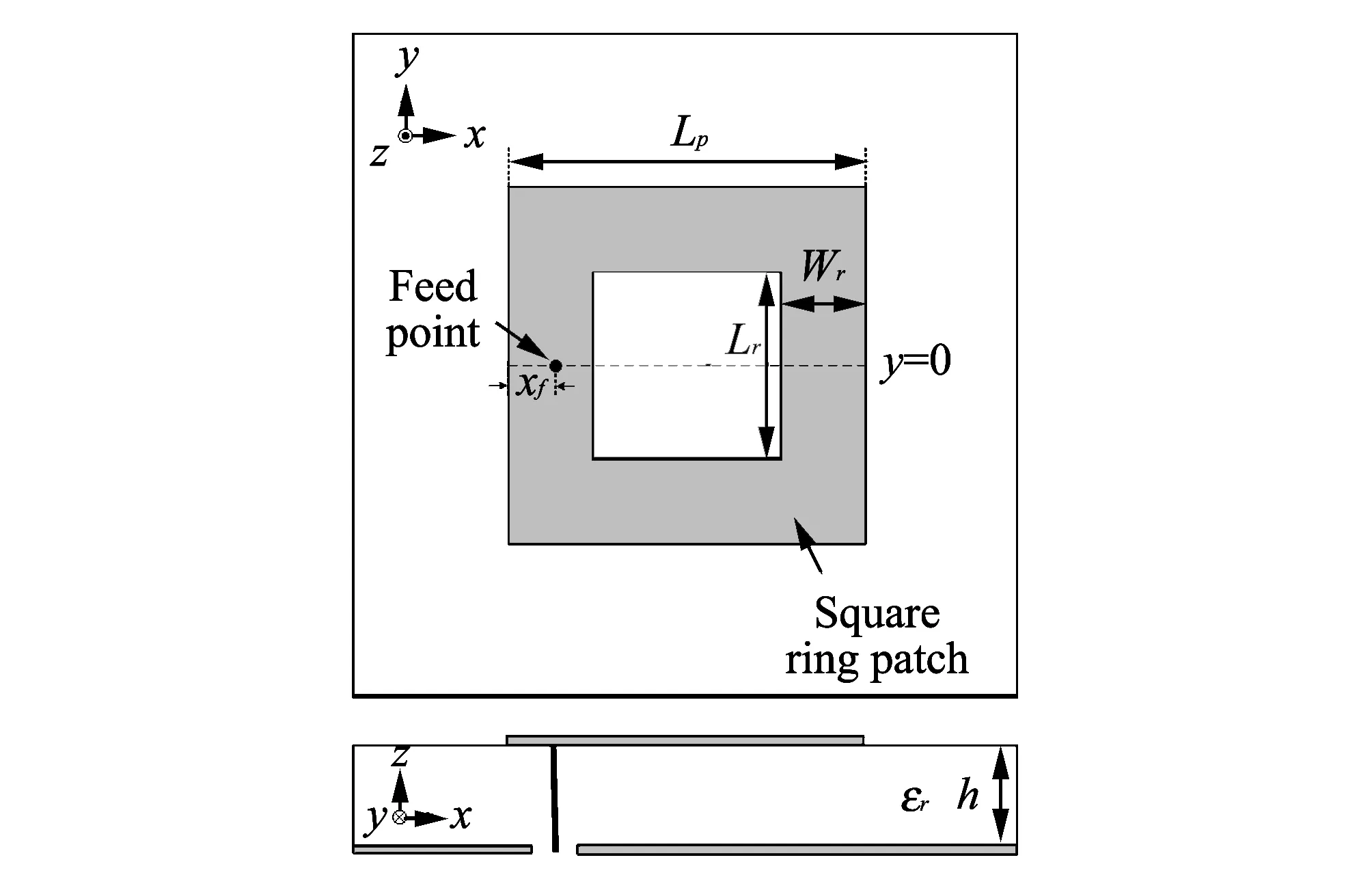
Fig.1 Geometry of a coaxial-fed ring patch antenna
1 Analysis of input impedance characteristic changes depending on capacitive feed patch
The capacitive feed method is used for the impedance matching in the square ring patch antenna. The geometry of the capacitive-fed square ring patch antenna is shown in Fig.2. The length of one side of the square ring patch, Lp, is 30 mm and the length of one side of removed square conducting portion, Lr, is 12 mm. In this section, the input impedance characteristics are investigated systematically for various size of the feed patch of the ring patch antenna.
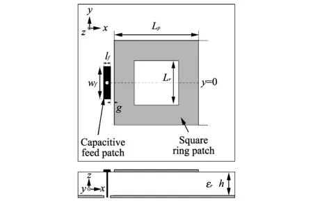
Fig.2 Geometry of a capacitive-fed ring patch antenna
Fig.3 presents the characteristics of the ring patch input impedance in case of changes depending on lf. In Fig.3(a), as lfincreasing with 2 mm, 3 mm and 4 mm, the maximum value of the antenna resistance tends to decrease, but frequency of the maximum resistance does not change.
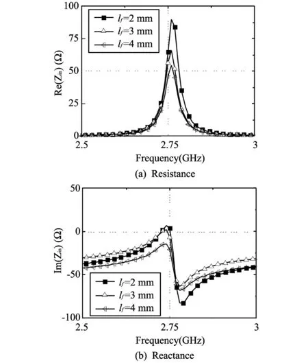
Fig.3 Input impedance characteristics of the square ring patch antenna for the various size of lf
Fig.3(b) shows that the maximum value of the antenna reactance decreases, while increasing lf. The characteristics of the input impedance of the ring patch antenna by changing lfare shown in Table 1.
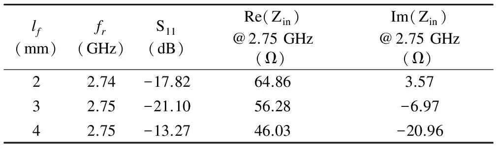
Table 1 Input impedance characteristics of the square ring patch antenna for the various size of lf
Fig.4 is impedance characteristic of ring patch antenna by changing wf.
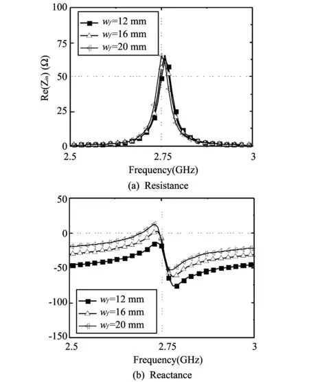
Fig.4 Input impedance characteristics of the square ring patch antenna for the various size of wf
In Fig.4(a), when wfis increasing with 12 mm, 16 mm and 20 mm, the maximum value of the antenna resistance tends to decrease, while frequency of the maximum resistance does not change. In Table 1, the change of the lfdoes not have a significant impact on the resonant frequency shifting and as lfincrease, resistance and reactance of the antenna tends to decrease. In Table 2, the change of the wfdoes not have a significant impact on the resonant frequency shifting. And as the wfincreasing, resistance of the antenna tends to increase and reactance tends to decrease.
Fig.5 is impedance characteristics of ring patch antenna by changing g. In Fig.5(a), when g increases with 0.1 mm, 0.3 mm and 0.5 mm, the maximum value of the antenna resistance tends to decrease while frequency of the maximum resistance tend to increase. In Fig.5(b), by increasing g, reactance of the antenna tends to increase.
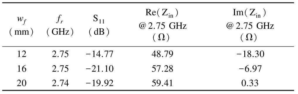
Table 2 Input impedance characteristics of the square ring patch antenna for the various size of wf
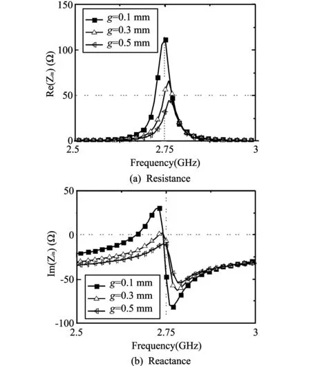
Fig.5 Input impedance characteristics of the square ring patch antenna for the various size of g
Table 3 summarizes the characteristics of input impedance of variation g of the ring patch antenna. In Table 3, the change of g does not affects frequency shifting. And as g increases, resistance of the antenna tends to increase in resonant frequency.
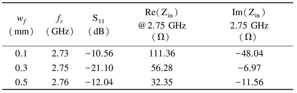
Table 3 Input impedance characteristics of the square ring patch antenna for the various size of g
2 Analysis of characteristics of ring patch antenna and general patch antenna
In Fig.2,Lris the length of square’s one side that removes square conducting portion. In conventional patch antenna,Lris 0 mm and its resonant frequency with fundamental mode is determined by effective dielectric constant and length of the microstrip patch antenna. In this section, resonant frequencies and radiation characteristics of conventional square patch antenna and square ring patch antennas for various size of Lrare researced. Fig.6 shows S11spectrum of the antennas when Lris 0 mm, 12 mm and 24 mm, respectively.
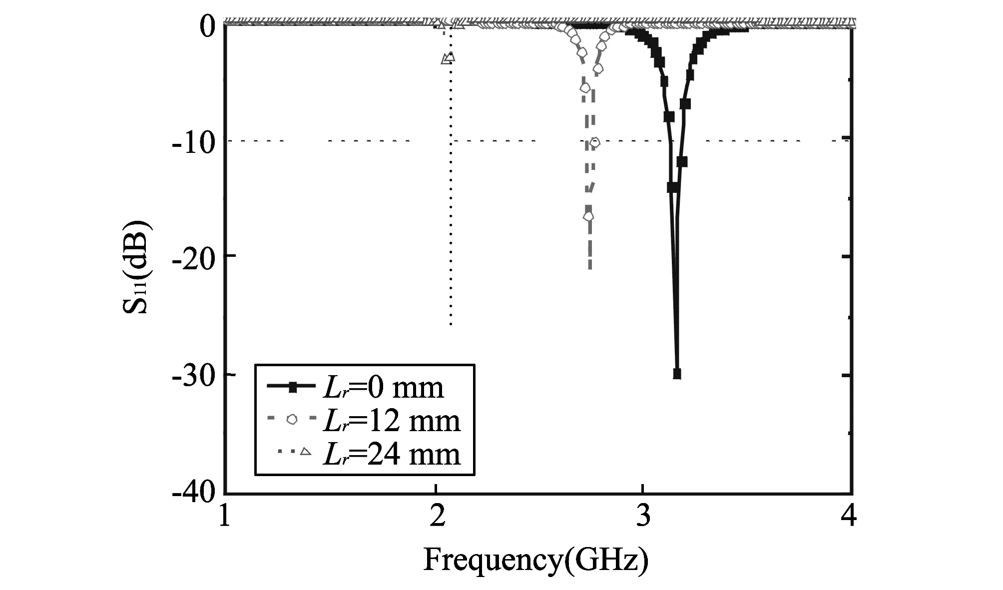
Fig.6 S11 spectrum for three different size of Lr of square ring patch antennas
In Fig.6, the antenna resonance frequency will decrease by increasing Lr. The antenna characteristics are given in Table 4.
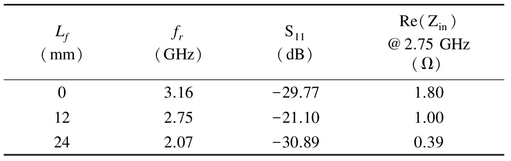
Table 4 Frequency characteristics for the three different size of Lr of square ring patch antennas
In Table 4, resonance frequency will decrease 3.16 GHz, 2.75 GHz, 2.07 GHz by increasing Lr. Also, 10 dB bandwidth will decrease by increasing Lr.
By increasing Lr, characteristics of the antenna are shown in Fig.7. It can be seen that the radiation pattern at antenna resonance frequency has the same radiation characteristics as that of the conventional patch antenna. Forward gain is the maximum when Lris 0 mm and it will decrease by increasing Lr. Radiation characterisuics at each resonance frequency are given in Table 5. It can be seen from Table 5, the ring patch antenna gain will decrease 8.18 dBi, 7.22 dBi and 5.79 dBi by increasing Lr. As Lrincreasing, difference between total gain and co-pol gain is very small that approaches 0 dBi.
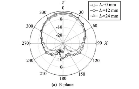
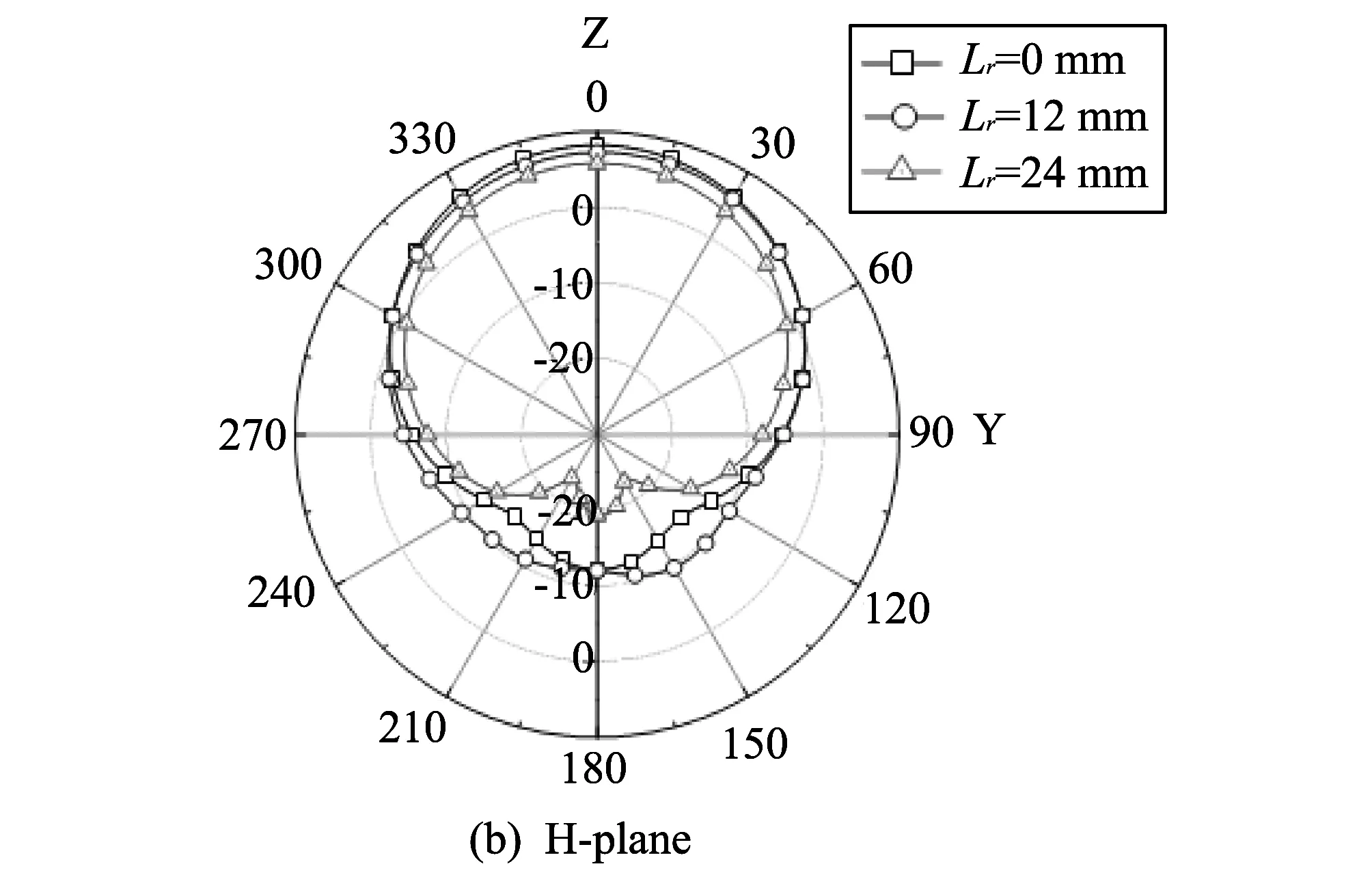
Fig.7 Radiation patterns for three different size of Lr of square ring patch antennas
3 Conclusion
In this paper, resonant frequencies and radiation characteristics of a square conventional microstrip patch antenna and square ring patch antennas are discussed. In case of Lr/Lp≥0.4 of square ring patch antennas, impedance matching are achieved by capacitive feed method. As Lris increases, resonant frequency of the antenna shifted to lower frequency and -10 dB bandwidth was decreased. The radiation patterns of square ring patch antennas at each resonant frequency characteristics are similar to those of a conventional patch antenna. As Lrdecreases, the antenna gain increases and cross polarization level increases.
[1] Garg R B. Microstrip antenna design handbook. 2nd edition. Artech House, London, 2001.
[2] Skrivervik A K, Zurcher J F, Staub O, et, al. PCS antenna design: the challenge of miniaturization. IEEE Antennas Propagation Magzine, 2001, 43(4): 12-27.
[3] Hsu S H, Ren Y J, Chang K, et al. Dual-polarized planar-array antenna for s-band and x-band airborne applications. IEEE Antenna and Propagation Magzine, 2009, 51(4): 70-78.
[4] Balanis C A. Antenna theory analysis and design. 2nd edition. John Wiley & Sons, Inc, New York, 1997.
[5] Latif S I, Shafai L. Investigation on the EM-coupled stacked square ring antennas with ultra-thin. IEEE Transaction on Antenna and Propagation, 2011, 59(11): 3978-3990.
dat3: 2012-09-15
Boogyoun Kim (bykim@e.ssu.ac.kr)
CLD number: TN823+.15 Document code: A
1674-8042(2013)01-0043-04
10.3969/j.issn.1674-8042.2013.01.010
杂志排行

Journal of Measurement Science and Instrumentation的其它文章
- Image enhancement and post-processing for low resolution compressed video
- Acetonitrile (CH3CN) and methyl isocyanide(CH3NC) adsorption on Pt(111) surface: a DFT study
- Erosion thermocouple temperature acquisition system
- Dynamic calibration method of capacitive pressure measuring device
- Automatic measurement of air-pressure sensor based on two-pressure control instrument
- An experiment to estimate the revolution of DC motor