Design of radiofrequency hyperthermia system based on MSP430
2013-10-19张思远韩醒之
张思远 王 迪 白 璐 韩醒之
(吉林大学 仪器科学与电气工程学院,吉林 长春 130026)
0 Introduction
It was reported that there were about 2 million to 180 million people who were with malignant tumor and about 1.5 million to 140 million people death of it in 2000 year in our country .And in past 30 years the mortality of malignant tumor had increased obviously in our country.Malignant tumor becomes the first killer of human in the 21st century.
The radiofrequency hyperthermia is a kind of medical intervention for tumor treatment by biological effect of heat such as microwave,the radio frequency and ultrasonic wave.With the use of this means,human tissues can stably rise to effective treatment region(41℃~45℃)and maintain a certain time to kill cancer cell without the damage of normal tissues[1].It is safe,reliable and people recover fast.
Experiments show that it will multiple the cell survival rate with the temperature difference of 1℃in 42℃.So the precise control of temperature is of great significance during the radiofrequency hyperthermia.
To achieve precise control of temperature,you are ought to accurately measure the temperature of the heated parts first.The temperature measurement is commonly used invasive temperature measurement which we can directly read the temperature by using the probe to implant temperature sensitive element to the predetermined portion under the image guidance.Also it has certain harm to patients.However,the noninvasive temperature measurement not only can overcome the above shortcomings but also reading the temperature parameter is lightly affected by the organizational structure.This system uses the infrared temperature sensor MLX90615 to achieve the non-contact measurement of the temperature.PID is suitable for the need for high accuracy measurement controlling system.Input the measured temperature and the preset temperature to PID unit can automatically calculate the duty ratio of PWM wave.
1 Hardware design of the system
According to the characteristics of biological tissue,radio frequency signal is chosen as the physical energy of heating and use the two plate capacitive heating modes.Modulating radio frequency signal on 500 kHz and adjustable duty ratio of PWM you will get the output signal to control full bridge inverter circuit.Then link up the whole bridge circuit and the heating plate.The hardware circuit mainly includes Infrared temperature measurement circuit,MSP430 controller,modulator circuit,driver circuit,the whole bridge chopper circuit,controlling keyboard of power system and liquid crystal display element.
1.1 The design of infrared measuring temperature
MLX90615 is a high precision infrared temperature sensor,it outputs temperature value through the I2C bus,its resolution is 0.02℃and measuring temperature is ranging from -40℃to 85℃,it satisfies the measurement requirement of the radio frequency heat temperature[2].
1.2 The AND gate modulation
Radio frequency heating is 500 KHZ square wave signal.First making the PWM wave of MSP430 output AND square wave of the radio frequency with 74F08,then you can get the output wave[3].Finally regard the modulation of the output waveform as full bridge inverter control signals.
1.3 Optical coupling isolation and drive circuit
In order to protect the digital circuit is not affected by the full bridge inverter with high voltage part,this system choose 6N137 optical coupling isolation.Radio frequency heating is of high frequency electromagnetic wave.In order to guarantee driving signal is not affected by input parasitic capacitance of the MOS pipe,this system adopts b complementary symmetry power amplifier.SIG1 and SIG2 is modulation signal.
1.4 The full bridge inverter circuit
Inverter circuit uses switch tube to get the DC voltage into AC voltage.This system adopts the whole bridge structure.The external Switching Power Supply provides 56V DC voltage.Choose IRF640 as MOS tube,S1 and S2 is connected to the heating plate.When M1 and M2 is conducting,M2 and M3 is cut-off,the current flows from the M1 to M4.When M2 and M3 is conducting,M1 and M4 is cut-off,Current flows from the M2 to M3.
2 The system software design
2.1 The infrared temperature measurement program design
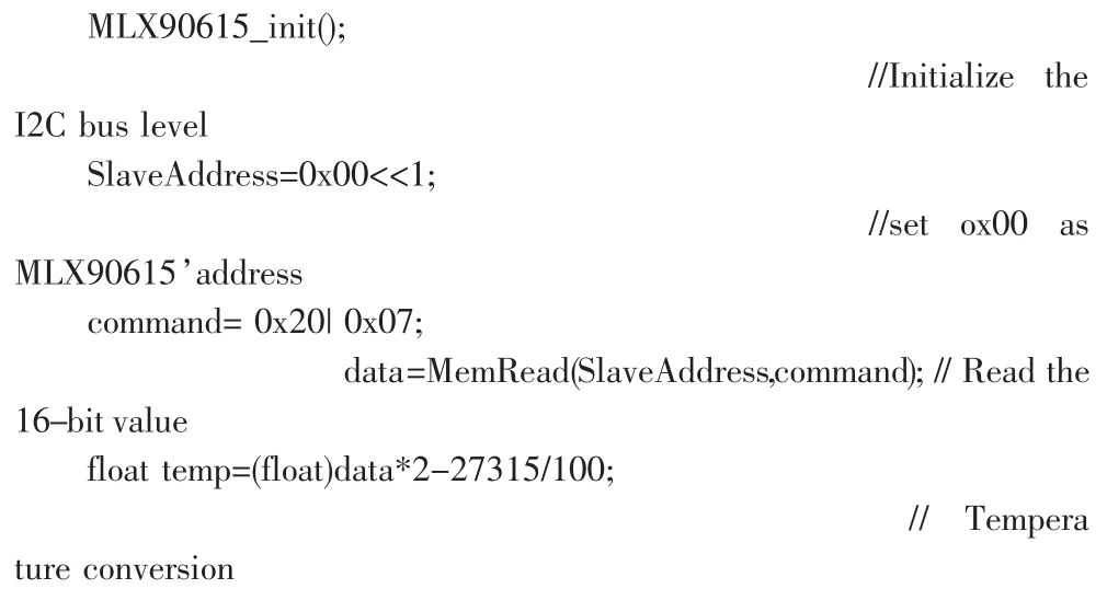
Read the 16 bit data in MLX90615 RAM address ox07 through the I2C bus.The main program is as follows:

2.2 MSP430 PWM program design
MSP430F149 has a 16 -bit timer/counter,owns three capture/compare register,it can provide PWM output with precise duty ratio[4].Register setting procedure is as follows:
TACCR0=10000;//the PWM output frequency is set 800 Hz
TACCTL1=OUTMOD2;
TACCTL2=OUTMOD2;
// the output mode is set activate/reset
TACTL|=TASSEL1+MC0+MC1;
// Set the clock source as 8MHz and add and subtract mode
TACCR1=duty1;
TACCR2=10000-duty;
2.3 PID algorithm design
Digital PID is easy to adjust,easy to implement and control precision,etc.It is widely used in control field.The expression of discrete PID is[5-6].

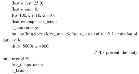
u0is the initial value of control amount,u(k)control the output,Kpis proportion amplification coefficient,Kiis integral amplification coefficient,Kdis differential amplification coefficient.In this system u0 is the initial value of control amount,e(i)is the difference between measurement temperature with setting temperature in the measure of the first i time,u(k)is PWM control amount of duty ratio in the first k times,the maximum is 5000.PID program is as follows:

3 The performance test and result analysis

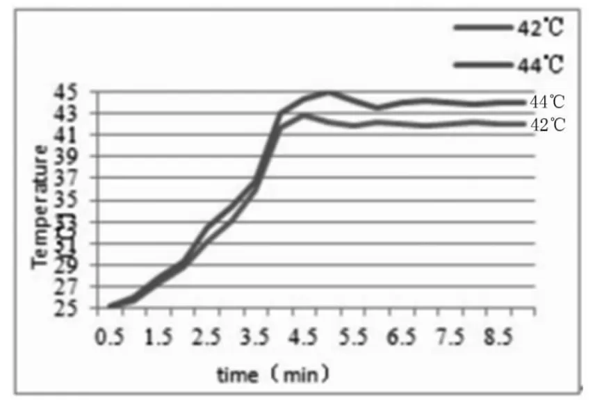
Fig1 Radiofrequency hyperthermia temperature control results
In order to test the designed radio frequency hypertherm ia measurement system and the performance of control system,design experiment as follows:
At room temperature (25 ℃),we take pig lean meat as heating object,and add the aluminum plate on both sides of the pork,the area of the heating plate for 10 cm by 10 cm.We place the infrared temperature sensor MLX90615 5 cm above the center of the pork,in order to test real -time temperature.Setting temperature of 42 ℃ and 44 ℃respectively,using the heat therapy system developed by this paper to heat the pork,recording the temperature every 30 seconds,drawing time-temperature curve is shown in figure 1.
As can be seen from the results that the temperature reaches the set value in 4 min,but the temperature will continue to rise,then over the set value,the temperature will stay in set value after adjusting for 2 min or so.
4 Conclusion
This paper briefly describes the basic principle of radio frequency heat,we design a high accuracy non -contact infrared temperature measurement circuit,using the PID algorithm to closed loop control of heating temperature,by setting the PWM duty cycle to change heating power,so as to realize the precise control of the temperature.Finally,the design of the radio frequency heat therapy system satisfies the requirement of radiofrequency hyperthermia.It can be seen from the test results.In order to achieve better temperature control effect,temperature field by using multiple infrared temperature sensors to measure temperature,and further optimize the control algorithm.
[1]Zhou Runjing,Tu Ya,Zhang Limin.FPGA/CPLD digital system design based on Quartus Ⅱ[M].Beijing:Publishing house of electronics industry,2008.
[2]Li Nana,Ma Youchun,Li Jinming.Infrared temperature measurement system design based on MSP430 and MLX90615[J].Journal of sensors and micro systems,2011,30(9):115-120.
[3]Tang Caigang,Zhu Hongtao,Li Li.The analysis of inverter circuit based on PWM[J].Modern electronics technique,2008(1):159-163.
[4]Xie Xinghong,Lin Fanqiang,Wu Xiongying.The base and practice of MS430 microcontroller[M].Beijing:Beijing university of aeronautics and astronautics press,2007.
[5]Wu Hongxin Shen Shaoping.The application and basic theory of PID[J].Control engineering of China,2003,10(1):37-42.
[6]Hu Shejiao,Xu Xiaobing,Yang Liu.Fuzzy PID temperature control instrument[J].Journal of Hefei university of technology (natural science),1998,21(5):151-154.
