大型客机座舱合理排数的数值模拟
2013-06-07刘俊杰刘素梅孙贺江肖晓劲
刘俊杰,刘素梅,孙贺江,肖晓劲
(1. 天津大学环境科学与工程学院,天津 300072;2. 中国商用飞机有限责任公司上海飞机设计研究院环控氧气系统设计研究部,上海 201210)
大型客机座舱合理排数的数值模拟
刘俊杰1,刘素梅1,孙贺江1,肖晓劲2
(1. 天津大学环境科学与工程学院,天津 300072;2. 中国商用飞机有限责任公司上海飞机设计研究院环控氧气系统设计研究部,上海 201210)
由于计算资源的限制,设计座舱的气流组织采用全舱数值模拟的方法不够科学,确定合理的座舱环境模拟排数是获得气流组织真实信息的基础.为此,用经过验证的计算流体力学(CFD)方法对单通道座舱合理排数进行了数值模拟研究,包括空舱及满员两种情况;研究的座舱排数分别为1排、3排、5排、7排及9排,模拟工况为热天巡航,数值模型采用RNG k-ε 模型.研究发现,对于空舱情况,由于复杂几何及边界条件对舱内气流的影响,至少需要5排座舱才能得到较合理的计算结果,7排及7排以上的座舱排数能得到准确的计算结果;满员情况下,由于人体热羽流对舱内气流流动起主导作用,故3排及以上的座舱排数能得到准确的计算结果.基于已确定的合理座舱排数,对半满员及满员两种情况下舱内的气流组织进行了对比分析.与满员情况下舱内气流组织呈对称分布不同,半满员情况下,每一排的气流都偏向人员多的一侧.
合理排数;计算流体力学;数值假人
随着社会的发展,人们对乘坐飞机出行的需求日益增加,对机舱内空气流动进行研究是创造一个安全、舒适、健康的机舱环境的必要前提.合理的气流组织形式是创造舒适客舱环境的关键.由于受多种流动机制,如复杂的边界条件、热浮力以及送风射流与热羽流的相互掺混等的影响,机舱内的流场很复杂.近几年随着计算流体力学(computational fluid dynamics,CFD)的飞速发展,CFD已经成为研究机舱内空气流动的有效工具[1-2].
对机舱内气流组织的正确研究方法应是对全舱进行模拟分析,但是研究发现即使采用计算集群,对全舱内污染物传播几分钟的数值模拟也需要几个星期的时间[3].以MD-82飞机为例,对4排经济舱空舱内气流组织进行模拟分析,网格数需要350×104以上,使用计算集群计算时间需要2,d以上.由于受计算资源的限制,研究人员只能截取飞机中的某一段作为研究对象进行研究.Dygert等[4]对单排座舱内通过设置局部排气对舱内污染物的传播及去除进行了数值模拟研究.Liu等[5]对3排空舱的几何模型进行了网格划分的简化研究;Zhang等[6-8]对4排座舱内空气流动及污染物传播等进行了数值模拟及试验研究;Yan等[9-14]对5排座舱内的气流组织、个性化送风及污染物传播进行了数值模拟或试验研究;Gupta等[15-16]对7排座舱内污染物的传播进行了深入的研究;Yin等[17]对8排座舱内不同污染物释放强度下乘客受感染的风险进行了数值模拟研究;Zhang等[18]对9排座舱内污染物传感器摆放位置的优化设计进行了数值模拟研究;Mazumdar等[19]提出了一个一维分析模型并将其与CFD模型耦合,对30排座舱内污染物的传播进行了模拟研究.
采用CFD研究机舱内气流时所采用的数值模型以RANS模型的应用最为广泛[20];同时,有研究介绍了数值模拟复杂机舱网格生成的几何简化方法[5].然而在现有的众多研究成果中,没有一项研究表明到底几排座舱的研究结果可以代表全舱的气流特性,Zhang等[7]研究发现,对4排座舱的研究结果对比中,CFD的计算结果与试验数据的差别甚至达到100%.由于现有研究所采用的几何模型、边界条件、研究对象等各不相同,不可能对现有结果进行定量的对比分析,因此需要对相同机舱几何模型、相同边界条件下的舱内气流组织进行研究,找出对机舱气流组织进行模拟研究的合理排数.
本文采用CFD的方法对机舱合理排数的确定进行了研究,确定合理排数的工况,包括空舱及满员两种工况;基于已确定的合理座舱排数,对半满员及满员两种情况下的舱内气流组织进行了对比分析.
1 研究方法
本文采用CFD对座舱内流场、温度场及湍动能分布进行预测.CFD中所用到的各控制方程的通用形式为

式中:φ为通用变量;,effφΓ为广义扩散系数;Sφ为广义源项;ρ为密度;ju为j方向的速度分量;jx为坐标系中j坐标方向.
1.1 CFD验证
根据Chen[21]的建议,首先对CFD计算进行验证.本文所用验证模型为MD-82飞机头等舱,其几何模型如图1所示.数值模型选用RNG k-ε 模型[20],压力与速度耦合采用SIMPLE算法,压力离散采用PRESTO! 算法.
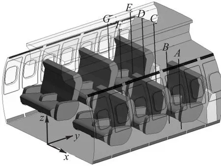
图1 用于CFD验证的几何模型Fig.1 Aircraft configuration used for CFD validation
图2 和图3给出了第3排横截面实测与模拟的流场对比结果及试验数据与CFD模拟值(速度v′、温度T′和湍动能E′)的对比结果.由于文章篇幅的限制,仅给出位置A的速度、温度及湍动能的对比结果.由于试验数据也存在一定误差(速度0.01,m/s,温度0.04,K[22]),可以认为数值模拟结果与试验结果在数值和趋势上均有较好的吻合.因此,这种数值方法用来预测座舱内流场情况也是可信的.
1.2 几何结构及网格
图4给出了本文采用的机舱几何结构.本研究所针对的机型为单通道座舱,基本型全经济布局168座,单排座舱的几何容积为6.9,m3,单排座舱几何尺寸为1.05,m(长)×3.6,m(宽)×2.2,m(高),座舱内座椅排与排之间的距离为0.8,m;对机舱合理排数的确定包括空舱及满员两种工况.舱内送风形式为混合通风,天花板附近设2个送风口(z=2.1,m),送风口宽度为24,mm,风速为0.6,m/s;行李架附近设2个送风口(z=1.6,m),送风口宽度为18,mm,风速为1.2,m/s;2个出风口设在地板附近(z=0,m),宽度为14.5,mm.两种工况下采用的机舱模型分别为1排、3排、5排、7排和9排.
本文采用的模拟工况为热天巡航.表1给出了该工况下的送风参数.

图2 第3排横截面上试验与模拟的流场分布Fig.2 Measured and simulated flow field distributions of the cross section in the third row
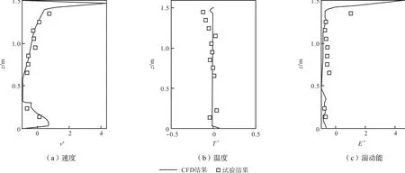
图3 位置A处CFD结果与试验数据的对比Fig.3 Comparisons of CFD results and experimental data at position A

图4 客机座舱空舱及满员的几何模型Fig.4 Aircraft configurations of the empty cabin and the fully-occupied cabin

表1 机舱送风参数Tab.1 Ventilation parameters for the aircraft cabin
网格的形式及数量由模型几何结构及计算资源决定.由于机舱及人体几何的复杂性,为了得到高质量同时网格数相对较少的网格,窗户、座椅及人体采用非结构网格,其余区域采用结构化网格.同时对靠近风口及人体附近的网格进行加密.图5展示了单排座舱空舱及满员情况下的网格和人体的网格.5种座舱排数空舱的网格数为:70×104、90×104、150× 104、220×104、360×104,满员的网格数为:130× 104、360×104、800×104、900×104、1,100×104.为了对满员及半满员情况下座舱内气流分布进行对比,本文也对半满员情况下座舱内气流组织进行了模拟分析.图6为半满员情况下的网格及人员分布情况,网格数为780×104.

图5 空舱、满员及人体网格Fig.5 Grids of the empty cabin,the fully-occupied cabin and the manikin

图6 半满员网格及人员分布Fig.6 Grid and manikin distribution pattern of the half-occupied cabin
2 结果分析
2.1 合理排数的确定
图7为空舱情况下的数据对比位置,图8给出了空舱及满员情况下中间横截面的速度v、温度T及湍动能E的分布.由于文章篇幅的限制,只给出了合理排数(空舱为7排,满员为3排)情况下的对比结果.可以看出两种情况下气流均呈对称分布.空舱情况下温度分布均匀,除风口及主流区域外,湍动能非常小;满员情况下,由于人体热羽流的影响,局部气流分布呈现较大的差别,乘客周围温度比舱内其他位置空气温度高,舱内整体及乘客周围湍动能都较空舱情况要高.
图9和图10为空舱情况下A′和B′位置不同座舱排数下速度v、温度T及湍动能k的对比结果,由于座舱复杂几何及边界对流场的影响,单排及3排座舱与其他排数下的模拟结果有明显差别,单排座舱与9排座舱计算结果最大误差可达83.3%,3排座舱与9排座舱计算结果最大误差可达33.3%,其余排数结果吻合程度较高,误差在10%以内.对于模拟精度要求不高的空舱算例,5排座舱可以得到相对较好的计算结果,7排及以上的座舱排数能得到正确的模拟结果.
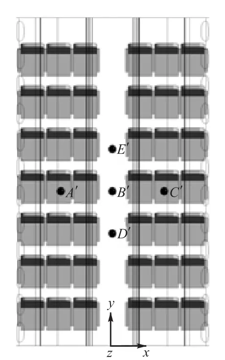
图7 空舱情况下数据对比位置Fig.7 Data comparison positions in the empty cabin
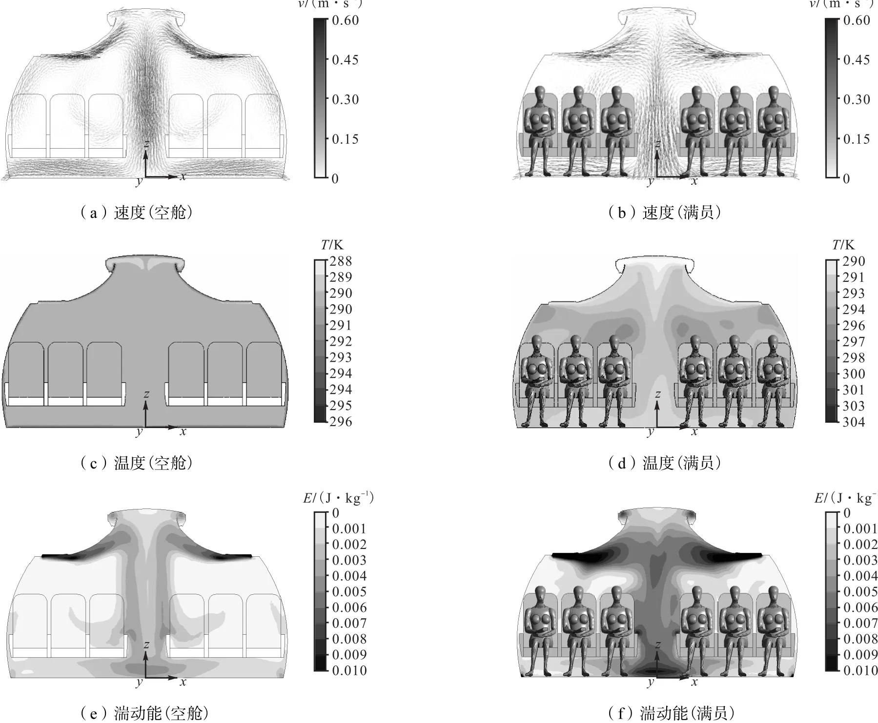
图8 空舱及满员情况下中间横截面上速度、温度及湍动能分布Fig.8 Velocity distribution,temperature distribution and turbulence energy distribution in the center cross section of empty cabin and the full-occupied condition
图11 为满员情况下的数据对比位置.由于文章篇幅的限制,图12和图13仅给出了位置B′′、D′′处的速度、温度和湍动能对比结果.满员情况下,与机舱几何边界的影响相比,舱内人体热羽流对舱内气流
的影响起主导作用,故除了单排座舱,其余排数的舱内模拟结果均吻合较好,平均误差在10%以内.可以认为对满员情况下舱内气流组织的模拟研究,3排及以上排数的座舱模型可以得到正确的计算结果.
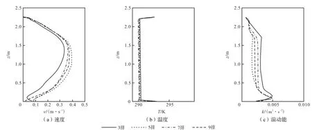
图9 空舱情况5种座舱排数下A′ 位置速度,温度和湍动能的对比Fig.9 Comparisons of air velocity,air temperature and turbulent intensity at position A′ of five different row numbers
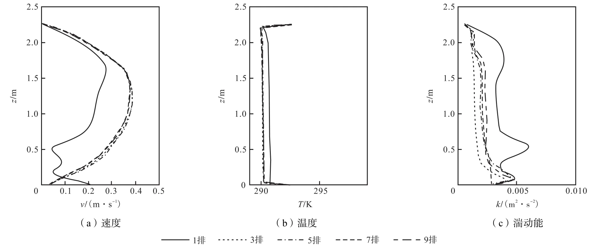
图10 空舱工况5种座舱排数下B′位置速度、温度和湍动能的对比Fig.10 Comparisons of air velocity,air temperature and turbulent intensity at position B′ of five different row numbers with the empty cabin
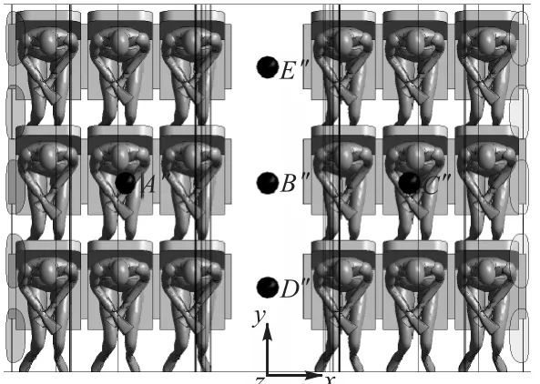
图11 满员情况下的数据对比位置Fig.11 Data comparison positions under the fully-occupied condition
由于人体温度与周围环境温度的差别,靠近人体附近的气流形式是自然对流还是混合对流取决于人体是否放置于停滞的空气中.人体周围热浮力的作用程度取决于格拉晓夫数与雷诺数的比值Gr/ Re2[23].此值达到或者超过1,即意味着流动中有强烈的浮力作用;反之,则流动中浮力作用可以忽略.本研究中满员工况下人体周围温差为14.7,℃,人体周围风速为0.16,m/s,人体特征长度取0.3,m,热膨胀系数为0.003,则该比值为5.1.这个数值证实了满员工况下人体周围热浮力对客机座舱内气流分布的强烈影响.
根据国际标准规范规定,客机座舱内空气流速分布应小于0.36,m/s,人体周围风速分布应小于0.3,m/s[24].对于类似构型的机型,在空舱及满员工况下,惯性力及热浮力各自所占的比重也应处于同一个水平,因此可以认为对于类似的机型,客机座舱的合理排数也处于同一个水平.
2.2 舱内气流组织的对比
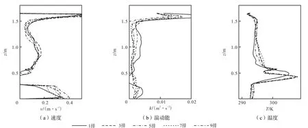
图12 满员工况5种座舱排数下位置B′′处速度、温度和湍动能Fig.12 Comparison of air velocity,air temperature and turbulent intensity at positions B′′ of five different row numbers in the full-occupied cabin
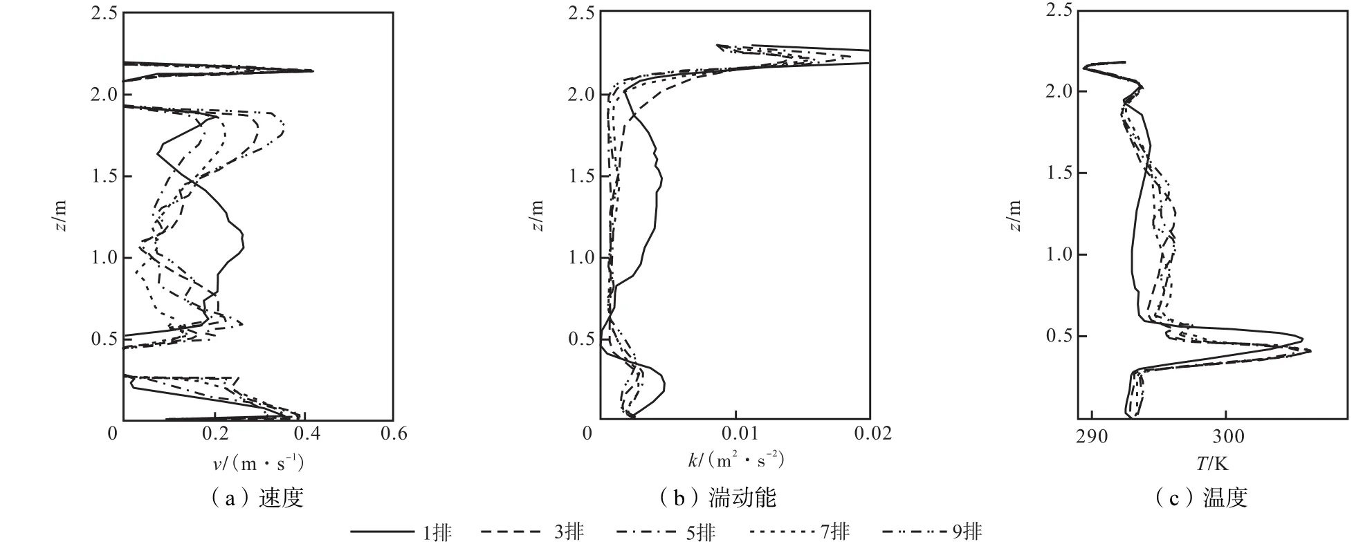
图13 满员工况5种座舱排数下位置D′′处速度、温度和湍动能对比Fig.13 Comparison of air velocity,air temperature and turbulent intensity at position D′′ of five different row numbers in the full-occupied cabin
根据得到的满员情况下座舱合理排数,本文进一步对半满员情况下舱内气流组织进行了模拟分析,并与满员情况进行了对比.考虑到半满员情况下人员比重减少,故选取5排座舱进行模拟研究.由于半满员情况下人员分布不均匀,舱内气流有很强的不稳定性,对半满员的数值模拟湍流模型选取非稳态的RNG k-ε 模型,时间步长为0.05,s.图14为满员情况下第3排中间断面及半满员情况下第2排、第3排、第4排中间断面上的速度分布. 两种情况下人体周围均有明显向上的热羽流;满员情况下,由于机舱几何结构对称及两侧乘客分布相同,舱内气流呈对称分布;而半满员情况下,受人员分布的影响,气流偏向人员分布密集的一侧;同时,由于人体周围热羽流的影响,人体与人体间有空座位时,该区域的气流速度明显大于人体与侧壁中间空座位区域的气流速度.
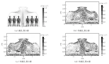
图14 满员第3排及半满员第2、第3、第4排中间横截面速度分布Fig.14 Velocity distributions in the center cross section of the third row in the fully-occupied cabin and the second,the third,the fourth row in the half-occupied cabin
3 结 语
为了科学合理模拟设计大型客机座舱气流组织,本文运用经过验证的计算流体力学(CFD)对单通道座舱合理排数进行了数值模拟研究.模拟工况为热天巡航,数值模型采用RNG k-ε 模型,对座舱合理排数的确定包括空舱及满员两种情况,研究的座舱排数为1排、3排、5排、7排和9排.研究发现对于空舱情况,由于复杂几何及边界条件对舱内气流的影响,至少需要5排座舱才能得到相对合理的计算结果,7排及7排以上的座舱排数能得到准确的结果,平均误差在10%以内;满员情况下,由于人体热羽流对舱内气流流动起主导作用,故3排及以上的座舱排数便能得到准确的计算结果.在确定了合理座舱排数的基础上,本文进而对半满员及满员两种情况下舱内的气流组织进行了对比分析,与满员情况下舱内气流组织呈对称分布不同,半满员情况下,每一排的气流都偏向人员较多的一侧.根据国际标准规范对客机座舱内气流分布参数的规定,可以得到对于类似构型的机型,本研究的结论仍然成立.
[1] Mazumdar Sagnik,Chen Qingyan. Response of contaminant detection sensors and sensor systems in a commercial aircraft cabin[C]//Proceedings of the 10th International IBPSA Conference(Building Simulation 2007). Beijing,China,2007:854-861.
[2] Dygert R K,Dang T Q. Experimental validation of local exhaust strategies for improved IAQ in aircraft cabins[J]. Building and Environment,2012,47(1):76-88.
[3] Mazumdar Sagnik,Chen Qingyan. Influence of cabin conditions on placement and response of contaminant detection sensors in a commercial aircraft[J]. Journal of Environmental Monitoring,2008,10(1):71-81.
[4] Dygert R K,Dang T Q. Mitigation of cross-contamination in an aircraft cabin via localized exhaust[J]. Building and Environment,2010,45(9):2015-2026.
[5] Liu W,Lin C-H,Liu J,et al. Simplifying the geometry of an airliner cabin for CFD simulations[C]// The 12th International Conference on Indoor Air Quality and Climate(Indoor Air 2011). Austin,TX,USA,2011:a118-3.
[6] Zhang Tengfei,Chen Qingyan. Novel air distribution systems for commercial aircraft cabins[J]. Building and Environment,2007,42(4):1675-1684.
[7] Zhang Tengfei,Chen Qingyan. Comparison of different ventilation systems for commercial aircraft cabins[C]// Proceedings of Indoor Air. Beijing,China,2005:3205-3210.
[8] Zhang Zhao,Chen Xi,Mazumdar Sagnik,et al. Experimental and numerical investigation of airf l ow and contaminant transport in an airliner cabin mockup[J]. Building and Environment,2009,44(1):85-94.
[9] Yan Wei,Zhang Yuanhui,Sun Yigang,et al. Experimental and CFD study of unsteady airborne pollutant transport within an aircraft cabin mock-up[J]. Building and Environment,2008,43(1):34-43.
[10] Matthias K,Johannes B,Claus W. Experimental parametric study of forced and mixed convection in a passenger aircraft cabin mock-up[J]. Building and Environment,2009,44(5):961-970.
[11] Gao N P,Niu J L. Personalized ventilation for commercial aircraft cabins[J]. Journal of Aircraft,2008,45(2):508-512.
[12] Zhang Tengfei,Yin Shi,Wang Shugang. An underaisle air distribution system facilitating humidif i cation of commercial aircraft cabins[J]. Building and Environment,2010,45(4):907-915.
[13] Wang Aijun,Zhang Yuanhui,Sun Yigang,et al. Experimental study of ventilation effectiveness and air velocity distribution in an aircraft cabin mockup[J]. Building and Environment,2008,43(3):337-343.
[14] Zhang Tengfei,Li Penghui,Wang Shugang. A personal air distribution system with air terminals embedded in chair armrests on commercial airplanes[J]. Building and Environment,2012,47(1):89-99.
[15] Gupta J K,Lin Chao-Hsin,Chen Qingyan. Inhalation of expiratory droplets in aircraft cabins[J]. Indoor Air,2011,21(4):341-350.
[16] Gupta J K,Lin Chao-Hsin,Chen Qingyan. Transport of expiratory droplets in an aircraft cabin[J]. Indoor Air,2011,21(1):3-11.
[17] Yin S,Sze-To G N,Chao C Y H. Retrospective analysis of multi-drug resistant tuberculosis outbreak during a fl ight using computational fl uid dynamics and infection risk assessment[J]. Building and Environment,2012,47(1):50-57.
[18] Zhang Tengfei,Chen Qingyan,Lin Chao-Hsin. Optimal sensor placement for airborne contaminant detection in an aircraft cabin[J]. HVAC and R Research,2007,13(5):683-696.
[19] Mazumdar Sagnik,Chen Qingyan. A one-dimensional analytical model for airborne contaminant transport in airliner cabins[J]. Indoor Air,2009,19(1):3-13.
[20] Liu Wei,Mazumdar Sagnik,Zhang Zhao,et al. Stateof-the-art methods for studying air distributions in commercial airliner cabins[J]. Building and Environment,2012,47(1):5-12.
[21] Chen Qingyan. Comparison of different k-ε models for indoor air flow computations[J]. Numerical Heat Transfer,1995(B28):353-369.
[22] Srebric J,Chen Qingyan. An example of verification,validation,and reporting of indoor environment modeling[J]. ASHRAE Transactions,2002,108(2):185-194.
[23] Gao N P,Niu J L. CFD study of the thermal environment around a human body:A review[J]. Indoor and Built Environment,2005,14(1):5-16.
[24] American Society of Heating,Refrigerating and Air-Conditioning Engineers. ANSI/ASHRAE Standard 161—2007 Air Quality Within Commercial Aircraft[S]. Atlanta,2007.
Numerical Simulation of the Reasonable Row Number for Commercial Aircraft Cabins
Liu Junjie1,Liu Sumei1,Sun Hejiang1,Xiao Xiaojing2
(1. School of Environmental Science and Engineering,Tianjin University,Tianjin 300072,China;2. Environment Control and Oxygen System Department,Shanghai Aircraft Design and Research Institute of Commercial Aircraft Corporation of China,Limited,Shanghai 201210,China)
Due to the limit of computing resources,it's difficult to process numerical simulation with a full-scale cabin. The determination of reasonable row number for aircraft cabin is the basis to acquire real information of airflow. This investigation explores the reasonable row number in a section of a single-aisle aircraft cabin with a validated computational fluid dynamics(CFD)program. The simulation of reasonable row number cases includes the empty cabin and the fully-occupied cabin and the row number differs from one row,three rows,five rows,seven rows to nine rows. The RNG k-ε model for the turbulent flow is used to simulate a steady air flow in the cabin environment during cruise flight. It found that as for the empty cabin,due to the influence of complex geometry boundary,five rows are enough for simple numerical simulation and the seven-row layout can obtain good results. As the thermal plume from manikin has larger impact on airflow distribution inside the aircraft cabin compared to geometry boundary,three rows are enough for the numerical simulation of the fully-occupied cabin. With the obtained reasonable full-occupied row number,this investigation further compares the air distribution between the halfoccupied cabin and the full-occupied cabin. The results show that different from the full-occupied condition,air distribution in the half-occupied aircraft cabin appears asymmetrical and airflow deviates from aisle to the side with more people.
reasonable row number;computational fluid dynamics (CFD);computational thermal manikin
V245.3
A
0493-2137(2013)01-0008-08
2012-09-03;
2012-10-18.
国家重点基础研究发展计划(973计划)资助项目(2012CB720100).
刘俊杰(1969— ),男,博士,教授.
刘俊杰,jjliu@tju.edu.cn.
