Heat transfer characteristics in micro-fin tube equipped with double twisted tapes: Effect of twisted tape and micro-fin tube arrangements*
2013-06-01EIAMSAARD
EIAMSA-ARD S.
Department of Mechanical Engineering, Faculty of Engineering, Mahanakorn University of Technology, Bangkok 10530, Thailand, E-mail: smith@mut.ac.th
WONGCHAREE K.
Department of Chemical Engineering, Faculty of Engineering, Mahanakorn University of Technology, Bangkok 10530, Thailand
Heat transfer characteristics in micro-fin tube equipped with double twisted tapes: Effect of twisted tape and micro-fin tube arrangements*
EIAMSA-ARD S.
Department of Mechanical Engineering, Faculty of Engineering, Mahanakorn University of Technology, Bangkok 10530, Thailand, E-mail: smith@mut.ac.th
WONGCHAREE K.
Department of Chemical Engineering, Faculty of Engineering, Mahanakorn University of Technology, Bangkok 10530, Thailand
(Received June 30, 2012, Revised October 31, 2012)
An experimental study was carried out to investigate the influence of double twisted-tape inserts (DTs) in micro-fin tubes (MFs) on heat transfer, friction factor and thermal performance factor characteristics of the compound devices in the following configurations: (1) twisted tapes acted in the same direction (for co-swirl) while MF and twisted tapes acted in the same (parallel) direction (MF-CoDTs:P), (2) twisted tapes acted in the same direction (for co-swirl) while micro-fin tube and twisted tapes acted in opposite directions (MF-CoDTs:O) and (3) twisted tapes acted in opposite directions for counter swirl (MF-CDTs). The MF alone and the MF equipped with a single twisted tape in parallel/opposite arrangement were also considered for comparison. The experiments were conducted for the flows with the Reynolds numbers between 5 650 and 17 000, under uniform heat flux condition. The experimental results indicate that MF-CDTs induce stronger swirl/turbulence flow, resulting in higher heat transfer rate, friction factor and thermal performance factor than other combined devices. The thermal performance factors associated with the use of MF-CDTs were found to be higher than those associated with the uses of MF-CoDTs:P, MF-CoDTs:O and MF alone up to 9.3%, 6.5% and 56.4%, respectively. The empirical correlations developed using the present experimental data for the Nusselt number, friction factor and thermal performance factor are also reported.
micro-fin tube (MF), double twisted-tapes (DTs), co-swirl, counter-swirl, heat transfer enhancement
Introduction
Swirl flow devices and modified surfaces have been widely employed in thermal engineering to enhance heat transfer. The typical actions of swirl flow devices are reducing the hydraulic diameter, increasing the effective axial Reynolds number and generating a tangential velocity component. Modified surfaces (such as finned and corrugated surfaces) increase the heat transfer surface area, disturb thermal boundary layer and promote fluid mixing[1-4].
To extend the potential of heat transfer enhancement, swirl flow devices have been combined with modified surfaces. Eiamsa-ard and Wongcharee[5]studied the characteristic of turbulent heat transfer in a micro-fin tube (MF) fitted with dual twisted tapes (DTs). Naphon and Sriromruln[6]applied a coiled wire as the swirl generator in a MF. Nagarajan et al.[7]used a modified twisted tape (left/right twisted tape) in a MF for heat transfer enhancement in a turbulent regime. Bharadwaj et al.[8]examined the heat transfer and friction in a spirally grooved tube with twisted tape insert. Saha et al.[9]and Saha[10]combined an axially corrugated circular duct with a center-cleared twisted-tape for greater enhancement than that offered by the corrugated circular duct alone. Similarly, Bhattacharyya and Saha[11]utilized a helically ribbed duct with a center-cleared twisted-tape. Recently, Promvonge et al.[12]reported the heat transfer enhancement in a helical-ribbed tube with double twisted tape inserts. In addition, Wongcharee and Eiamsa-ard[13]investigated the effect of corrugated tube equipped with twisted tape on the heat transfer enhancement using CuO/water nanofluid as a working fluid. The compound devices in the previous studies are shown in Fig.1. In general, compound devices offer superior heat enhancement to a single device due to a synergetic effect. Although many compound devices have been examined, the one consisting of a MF and DTs,has not been found. Therefore, the present work proposes the compound device. In addition, this work aims to find the optimum configuration and also geometry of the device. The configurations and geometries considered in the present work are described in the following section.
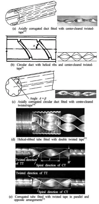
Fig.1 Compound devices for heat transfer enhancement found in the previous studies
1. MF fitted with DTs
The MF was made from copper, and its inner diameter, outer diameter and length were 8.64 mm, 9.52 mm and 700 mm, respectively. The geometry of the tube is shown in Fig.2(a). Twisted tape was made of aluminum sheet that was 0.8 mm thick and 700 mm long. DTs consisted of two identical tapes, and each tape was 4 mm wide while the single twisted tape was 8 mm wide. The twist ratio (y/ W)of twisted tape was varied from 3.0 to 5.0 (yis defined as the length with 180orotation). The MF and double twisted tape were arranged in 3 different forms: (1) twisted tapes acted in the same direction (for co-swirl) while MF and twisted tapes acted in the same (parallel) direction (MF-CoDTs:P), (2) twisted tapes acted in the same direction (for co-swirl) while MF and twisted tapes acted in opposite directions (MF-CoDTs:O) and (3) twisted tapes acted in opposite directions for counter swirl (MF-CDTs). The MF with a single twisted tape was arranged in 2 different forms: (1) micro-fin and single twisted tape acted in the same (parallel) direction (MF-ST:P), (2) micro-fin and single twisted tape acted in opposite directions (MF-ST:O). The single twisted tape and dual twisted tapes as well as their geometries and arrangements are shown in Fig.2(b) while the combined devices are shown in Fig.3.
2. Experimental set-up
A schematic view and sectional view of the experimental set-up is shown in Fig.4. The test section consisted of three consecutive parts: a calm (entrance) section, a test section and an exit section with the lengths of 1 000 mm, 700 mm and 500 mm, respectively. The outer surface the MF was covered with a heating wire and subsequently well insulated to minimize heat transfer to surroundings. Fifteen thermocouples (T type) were located on the outer tube wall to measure the local wall temperature while the RTDs were used to measure inlet and outlet water temperatures of the test section. Heat flux was varied via the variac transformer connected to the electric heater. A mixing chamber was located downstream of the test section. The volumetric water flow rate was controlled using a globe valve and measured using a rotameter, located upstream of the test section. The pressure drop across the test tube was measured using two static pressure taps.
During experiments, cold water was pumped through the test section under a uniform wall heat flux condition. Temperatures of the inlet and outlet water, as well as a pressure drop were recorded in steady state. Experiments were performed for Reynolds numbers ranging from 5 650 to 17 000, based on the inlet tube diameter.
3. Data acquisition and uncertainty analysis
The average Nusselt number and the friction factor are based on the hydraulic diameter of the MF. Heat absorbed by the cold water under a uniform heat flux condition,Qccan be expressed as
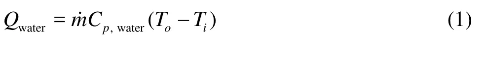
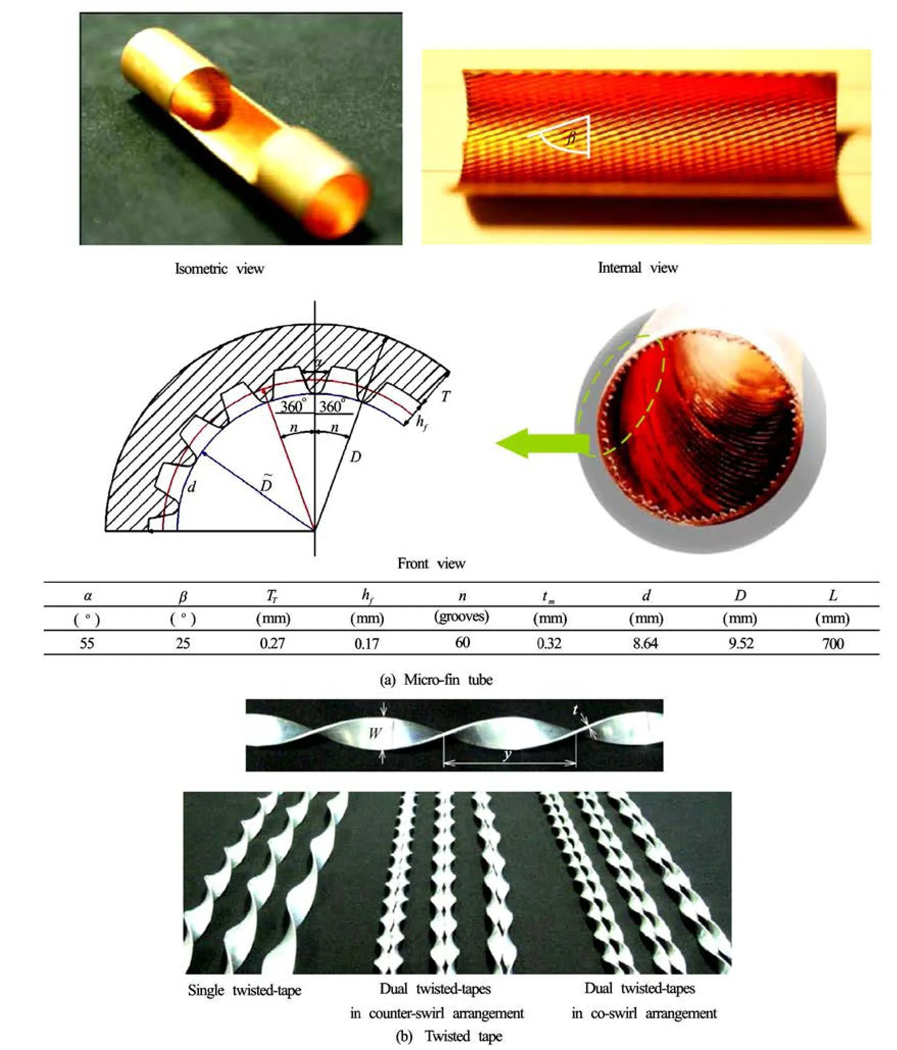
Fig.2 Picture view of single twisted tape and double twisted tapes with different arrangements and MF
where m˙is the mass flow rate of water,Cp,wateris the specific heat of water,Tiand Toare the inlet and outlet water temperatures, respectively. At thermal equilibrium, heat absorbed by water was found to be 4% to 8% lower than the heat supplied by the heater wire to the MF due to convection and radiation hea losses from the MF to surroundings. The heat transfer rate in steady state is assumed to be t

The heat transfer rate through the test section can be written as

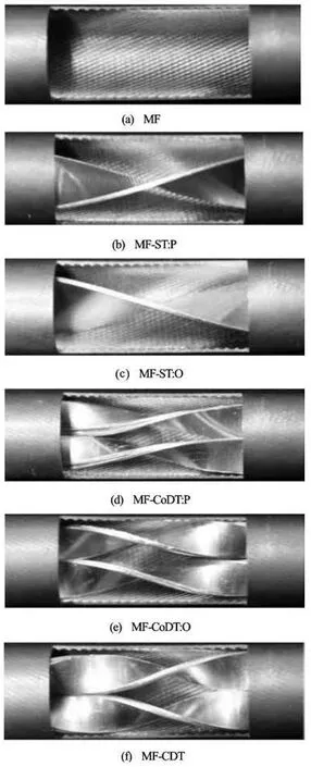
Fig.3 Photographs of MF fitted with twisted tapes with different arrangements
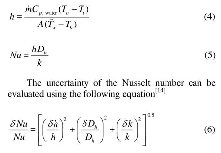
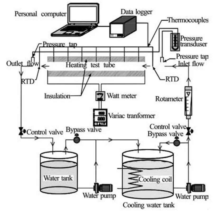
Fig.4 Schematic diagram of heat transfer apparatus
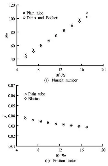
Fig.5 Validation of the plain tube
The Reynolds number is given by
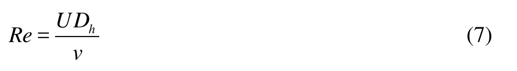
The uncertainty of the Reynolds number can be determined by the following equation[14]
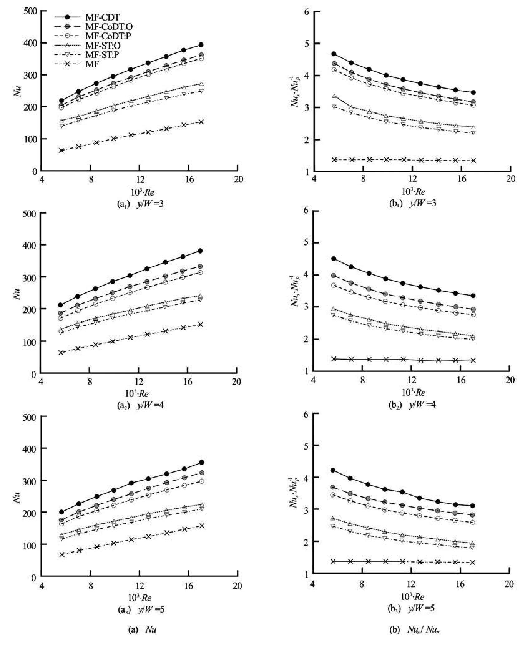
Fig.6 Effect of MF equipped with DTs on heat transfer
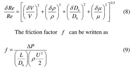
The uncertainty of friction factor can be determined by the following equation[14]
The maximum uncertainties of the Reynolds number, Nusselt number and friction factor (non-dimensional parameters) in the present work were 3.5%, 5.2% and 4.8%, respectively.
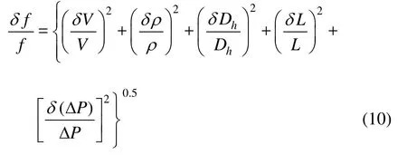
Fig.7 Effect of MF fitted with DTs on friction factor
To assess the practical use of the enhanced tube, the performance of the enhanced tube is evaluated relatively to that of the plain tube at an identical pumping power in the form of thermal performance factor which can be expressed as

4. Experimental results
The experimental results of heat transfer in a MF with DTs of in different arrangements (MF-CoDTs:P, MF-CoDTs:O, MF-CDTs, MF-ST:P, MF-ST:O) are described in this section. The results of heat transfer and friction are reported in terms of the Nusselt number(Nu)and friction factor(f), respectively. To evaluate the reliability of the present experimental set-up, the results of the present plain tube were validated with those obtained from the correlations available in the previous work[15], and the validations are shown in Fig.5. The comparisons reveal that the pre-sent data agree well with those from the correlations within ±2.7% and ±3.8% for the friction factor and Nusselt number, respectively.
4.1 Heat transfer
Figures 6(a)-6(b) presents the variation of the Nusselt number with the Reynolds number. For all cases, the Nusselt number increases with increasing Reynolds number while the Nusselt number ratio (Nu/ Nup)exhibits an opposite trend. This indicates that the heat transfer enhancement is less significant as the Reynolds number increases, in view of the fact that a thermal boundary layer is thinner at higher Reynolds number. In addition, the Nusselt number increases as the twist ratio decreases, due to an increase of turbulence intensity. In general, the MFs with twisted tapes offers significantly higher Nusselt number than the one without twisted tape. This reveals the influence of the effective disruption of a thermal boundary layer by swirl flow. The MFs with DTs provides noticeably higher Nusselt number than the one with a single twisted tape, because double swirl flows generate higher turbulence intensity than a single swirl flow as was reported by Wongcharee and Eiamsaard[13]. It could also be observed that the heat transfer enhancement is influenced by the arrangement of MF and twisted tapes. The DTs arranged to produce counter swirl flows (CDTs) give higher Nusselt number than the ones arranged to produce co-swirl flows (CoDTs). Similarly, MF and twisted tapes acted in opposite (O) directions provide higher Nusselt number than the ones acted in the same direction (parallel (P) arrangement). The superior heat transfer can be explained by the extra turbulence caused by the counter flow resulting in better fluid mixing between core and wall regions. For the range determined, MF-CDTs give higher Nusselt number than MF-CoDTs:P, MFCoDTs:O, MF-ST:P and MF-ST:O by around 11.4%-22.6%, 6.7%-14.6%, 53.6%-72.3% and 39.3%-60.6%, respectively. The average Nusselt numbers associated by the uses of MF-CoDTs:P, MF-CoDTs:O, MFCDTs, MF-ST:P and MF-ST:O are respectively found to be around 91%-201%, 108%-214%, 129%-235%, 34%-118% and 43%-140% higher than that given by the MF alone. However, with twisted tape inserts, heat transfer rate increases at the expenses of high pressure losses.
4.2 Friction factor
The variation of the friction factor with the Reynolds number is demonstrated in Figs.7(a)-7(b). Apparently, the friction factor slightly decreases with increasing Reynolds number. However, the friction factor change is insignificant in case of MF alone. The effect of twist ratio and the arrangement of MF and twisted tapes on friction factor are in similar manner found for the Nusselt number. This can be explained by the fact that the dissipation of dynamic pressure increases as turbulence intensity becomes stronger. The friction factors associated with MF-CoDTs:P, MFCoDTs:O, MF-CDTs, MF-ST:P and MF-ST:O are respectively around 71%-81%, 75%-83%, 79%-84%, 57%-74% and 60%-75% higher than that caused by the MF alone. Comparatively, the friction factor generated by the DTs acted in opposite directions is noticeably higher than that generated by the ones acted in the same direction. As was found, the use of MFCDTs results in higher mean friction factor than the uses of MF-CoDTs:P and MF-CoDTs:O by around 47.2% and 46.5%, respectively
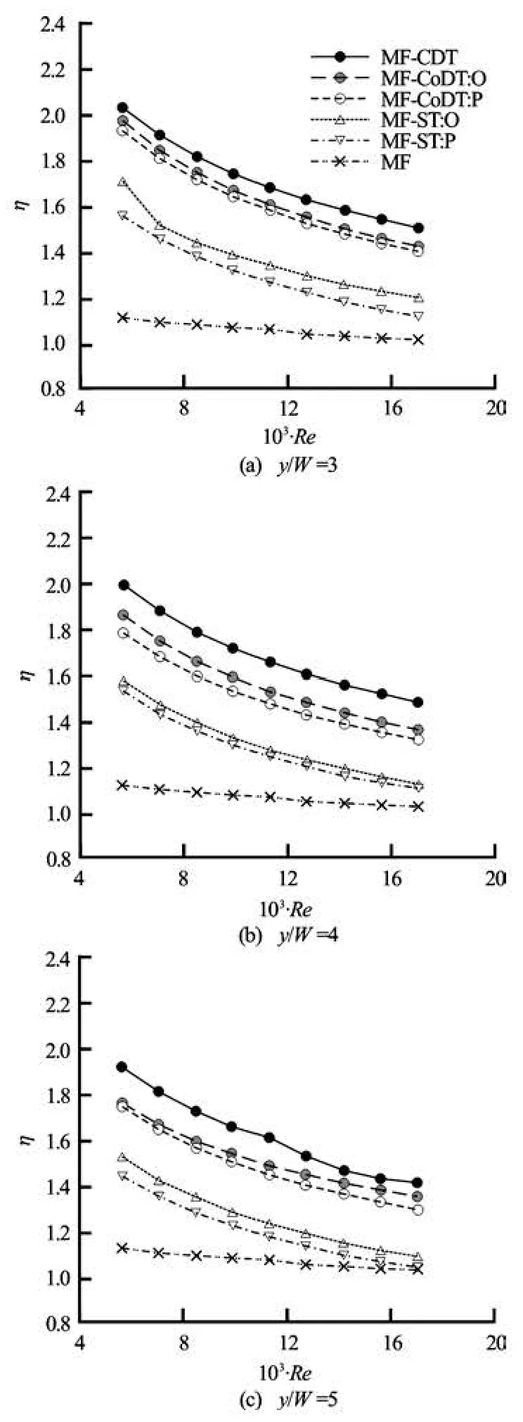
Fig.8 Effect of MF fitted with DTs on thermal performance factor
4.3 Thermal performance factor
The variation of the thermal performance factor with the Reynolds number is shown in Fig.8. It is found that the thermal performance of the MF equipped with twisted tapes considerably decreases with increasing Reynolds number. For all cases examined, thermal performances factors are found to be higher than unity. This is attributed to a good trade-off between the heat transfer improvement and the increase of pressure drop or friction penalty. In addition, the thermal performance factor associated by DTs is higher than that associated by a single twisted tape. The DTs arranged to produce counter swirl (CDTs) give higher thermal performance factor than the ones arranged to produce co-swirl (CoDTs). The MF and twisted tapes acted in opposite directions provided higher thermal performance factor than the ones acted in the same direction (or parallel (P) arrangement). The higher thermal performance factor is explained by the dominant effect of heat transfer enhancement over that of the increase friction factor at the same pumping power.
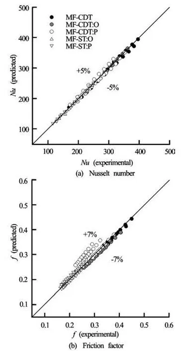
Fig.9 Predicted data by empirical correlations versus measured data
The thermal performance factors for the studied cases are between 1.03 and 1.12 for MF alone, 1.29 and 1.94 for MF-CoDTs:P, 1.35 and 1.97 for MFCoDTs:O, 1.41 and 2.03 for MF-CDTs, 1.04 and 1.57 for MF-ST:P, and 1.08 and 1.71 for MF-ST:O. The highest thermal performance factor is offered by MFCDTs. For the range investigated, MF-CDTs give higher thermal performance factor than MF alone, MF-CoDTs:P, MF-CoDTs:O, MF-ST:P and MF-ST:O by around 37%-81%, 5%-12%, 3%-9.5%, 29%-37% and 19%-32%, respectively.
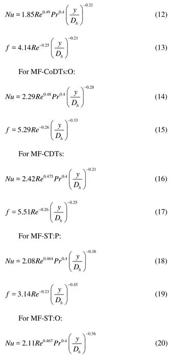
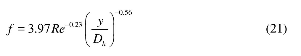
4.4 Empirical correlations
The experimental results in the present work are subjected to the development of empirical correlations. The resultant correlations are shown below.
For MF-CoDTs:P:
The reliability of the correlations is evaluated by comparing the predicted data to the measured data. The comparison in Figs.9(a)-9(b) suggests that the predicted data agree well with the measured data within ±5% and ±7% for the Nusselt number and friction factor.
5. Conclusions
The effects of a MF equipped with single twisted tape/DTs in different arrangements on heat transfer enhancement are reported. The major findings are drawn as follows:
(1) The MF with DTs provides noticeably higher Nusselt number and thermal performance factor than the one with a single twisted tape.
(2) The DTs arranged to produce counter swirl (CDTs) give higher Nusselt number and thermal performance factor than the ones arranged to produce coswirl (CoDTs).
(3) The MF tube and twisted tapes acted in opposite (O) directions offer higher Nusselt number as well as thermal performance factor than the ones acted in the same direction (in parallel (P) arrangement).
(4) The maximum thermal performance factor of 2.03 is achieved by the use of the MF and DTs which generated counter swirl (MF-CDTs).
Acknowledgments
The authors would like to acknowledge with appreciation, the Thailand Research Fund (TRF), Office of Higher Education Commission and Mahanakorn University of Technology (MUT) for financial support of this research (Grant No. MRG5480026).
[1] CUI Yong-zhang, TIAN Mao-cheng. Three-dimensional numerical simulation of thermal-hydraulic performance of a circular tube with edgefold-twisted-tape inserts[J]. Journal of Hydrodynamics, 2010, 22(5): 662-670.
[2] JAISANKAR S., RADHAKRISHNAN T. K. and SHEEBA K. N. Experimental studies on heat transfer and thermal performance characteristics of thermosyphon solar water heating system with helical and leftright twisted tapes[J]. Energy Conversion and Management, 2011, 52(5): 2048-2055.
[3] MURUGESAN P., MAYILSAMY K. and SURESH S. et al. Heat transfer and pressure drop characteristics in a circular tube fitted with and without V-cut twisted tape insert[J]. International Communications in Heat and Mass Transfer, 2011, 38(3): 329-334.
[4] MURUGESAN P., MAYILSAMY K. and SURESH S. Heat transfer and friction factor studies in a circular tube fitted with twisted tape consisting of wire-nails[J]. Chinese Journal of Chemical Engineering, 2010, 18(6): 1038-1042.
[5] EIAMSA-ARD S. and WONGCHAREE K. Singlephase heat transfer of CuO/water nanofluids in microfin tube equipped with dual twisted-tapes[J]. International Communications in Heat and Mass Transfer, 2012, 39(9): 1453-1459.
[6] NAPHON P., SRIROMRULN P. Single-phase heat transfer and pressure drop in the micro-fin tubes with coiled wire insert[J]. International Communications in Heat and Mass Transfer, 2006, 33(2): 176-183.
[7] NAGARAJAN P. K., MUKKAMALA Y. and SIVASHANMUGAM P. Studies on heat transfer and friction factor characteristics of turbulent flow through a micro-finned tube fitted with left–right inserts[J]. Applied Thermal Engineering, 2010, 30(13): 1666-1672.
[8] BHARADWAJ P., KHONDGE A. D. and DATE A. W. Heat transfer and pressure drop in a spirally grooved tube with twisted tape insert[J]. International Journal of Heat and Mass Transfer, 2009, 52(7-8): 1938-1944.
[9] SAHA S. K., BHATTACHARYYA S. and PAL P. K. Thermohydraulics of laminar flow of viscous oil through a circular tube having integral axial rib roughness and fitted with center-cleared twisted-tape[J]. Experimental Thermal and Fluid Science, 2012, 41: 121-129.
[10] SAHA S. K. Thermohydraulics of laminar flow of viscous oil through a circular tube having axial corrugations and fitted with centre-cleared twisted-tape[J]. Experimental Thermal and Fluid Science, 2012, 38: 201-209.
[11] BHATTACHARYYA S., SAHA S. K. Thermohydraulics of laminar flow through a circular tube having integral helical rib roughness and fitted with centre-cleared twisted-tape[J]. Experimental Thermal and Fluid Science, 2012, 42: 154-162.
[12] PROMVONGE P., PETHKOOL S. and PIMSARN M. et al. Heat transfer augmentation in a helical-ribbed tube with double twisted tape inserts[J]. International Communications in Heat and Mass Transfer, 2012, 39(7): 953-959.
[13] WONGCHAREE K., EIAMSA-ARD S. Heat transfer enhancement by using CuO/water nanofluid in corrugated tube equipped with twisted tape[J]. International Communications in Heat and Mass Transfer, 2012, 39(2): 251-257.
[14] SAHA S. K. Thermohydraulics of turbulent flow through rectangular and square ducts with axial corrugation roughness and twisted-tapes with and without oblique teeth[J]. Experimental Thermal and Fluid Science, 2010, 34(6): 744-752.
[15] INCROPERA F. P., DEWITT P. D. and BERGMAN T. L. et al. Fundamentals of heat and mass transfer[M]. New York, USA: John-Wiley and Sons, 2006.
Nomenclature
A– Heat transfer surface area
Cp– Specific heat of fluid
Dh– Hydraulic diameter of MF
f – Friction factor = ΔP /[(L/ D )(ρ u2/2)]
h
h– Heat transfer coefficient
k – Thermal conductivity of fluid
L– Length of the test section
m˙– Mass flow rate
Nu – Nusselt number =hD/ k
P– Pressure of flow in stationary tube
ΔP– Pressure drop
Pr – Prandtl number =µCp/k
Q– Heat transfer rate
Re – Reynolds number =ρUDh/μ
T– Local temperature
T– Mean temperature
U– Mean axial flow velocity
W– Twisted tape width
y– Twisted tape pitch
Greek symbols
ρ– Fluid density
µ– Fluid dynamic viscosity
η– Thermal performance factor
Subscripts
b– Bulk
c – Convection
i – Inlet
o– Outlet
p– Plain tube
w– Wall
Abbreviations
MF– Micro-fin tube
MF-CoDTs:P– Micro-fin tube equipped with double twisted tapes: twisted tapes produced co-swirl while micro-fin tube and twisted tapes acted in the same direction (parallel (P) arrangement)
MF-CoDTs:O– Micro-fin tube equipped with double twisted tapes: twisted tapes produced co-swirl while micro-fin tube and twisted tapes acted in opposite (O) directions
MF-CDTs– Micro-fin tube equipped with double twisted tapes: twisted tapes produced counter swirl
MF-ST:P– Micro-fin tube equipped with single twisted tape: micro-fin tube and twisted tape acted in the same direction (parallel (P) arrangement)
MF-ST:O– Micro-fin tube equipped with single twisted tape: micro-fin tube and twisted tape acted in opposite (O) directions
10.1016/S1001-6058(13)60355-8
* Biography: EIAMSA-ARD S. (1973-), Male, Ph. D., Associate Professor
杂志排行

水动力学研究与进展 B辑的其它文章
- Hydrodynamic modeling of cochlea and numerical simulation for cochlear traveling wave with consideration of fluid-structure interaction*
- Orientation of the fiber suspending in the flow through a tube containing a sphere*
- Numerical analysis of vortex core phenomenon during draining from cylinder tank for various initial swirling speeds and various tank and drain port sizes*
- Radiation and diffraction analysis of a cylindrical body with a moon pool*
- Stochastic simulation of fluid flow in porous media by the complex variable expression method*
- Effects of high-order nonlinearity and rotation on the fission of internal solitary waves in the South China Sea*