PROCESSING PARAMETER OPTIMIZATION OF FDM BASED ON ROBUST DESIGN
2012-10-08ZhangJianfengPengAnhua
Zhang Jianfeng,Peng Anhua
(1.College of Mechanical Engineering,Yangzhou University,Yangzhou,225009,P.R.China;2.Engineering Training Center,Huaihai Institute of Technology,Lianyungang,222005,P.R.China)
INTRODUCTION
Fused deposition modeling(FDM)technology has widespread applications in rapid prototyping manufacturing. Compared with traditional technology,FDM has considerable advantages in manufacture costs,efficiency,adaptability,and flexibility. However, fabricating precision of FDM is relatively lower at present.Therefore,how to improve the precision of prototyping parts is still a hot issue on rapid prototyping manufacturing.The precision of parts directly affects the quality of the final product,especially when the parts are used as plastic mould,EDM electrode,and so on for bulk production.Processing parameter optimization is the major method in improving the precision of parts during rapid prototyping.The current research is mainly focused on theinfluence of single processing parameter on dimensional accuracy of parts[1-2].Multi-parameter coupling effect on dimensional accuracy of parts has not been sufficiently studied.For this reason,the optimal scheme is difficult to be obtained in most cases. Thus,the quality of prototyping parts cannot fully meet the requirement of design.
In this paper,robust design analysis and multi-index fuzzy comprehensive assessment method are developed to optimize the processing parameters of FDM.The optimal combination of the processing parameters can be used for a high precision manufacturing.
1 ROBUST DESIGN METHOD
Robust design is an optimal design method for quality engineering which is proposed from the industrial products and process quality control.Signal-to-noise ratio(SNR)and orthogonal array are two main tools of robust design[3].
SNR is used to measure the index fluctua-tions in parameter design.It is thecore of parameter design.As ameasureindex of performanceevaluation,in theory,the greater the SNR is,the better the performance is.Two indexes,size error and warpage,are studied in the experiments.Theoretically speaking,the smaller these two indexes are,the higher product precision is.Size error and warpagehave smaller-the-better characteristic,which means that the closer to zero the performance indexes of the product are,the better the performance is.Zero is the ideal value of SNR.As to the index of smaller-the-better(STB)characteristic,SNR Z is defined as[4]

where n is the number of replicate tests,yi the index value of the i th experiment.
Orthogonal array has two features:equivalent conjugation and comprehensive comparison[5],so exhaustive experimentation can be replaced by a small number of experiments.For this reason,the costs of manpower,materials and time in the experimental process can be saved greatly.Equivalent conjugation refers that all levels of each factor are selected uniformly,and each combination of every two levels is tested in n times orthogonal experiments. Comprehensive comparison is defined as data comparison of one factor in various levels under the condition that other factors are equal.Standardized orthogonal array is expressed by symbol LK(PJ),where L is the orthogonal array of the experimental program arranged,K the number of experimental programs or experimental conditions,namely,K represents different combinations of every level and the number of orthogonal array rows,P the number of levels,and J the number of orthogonal array columns,which shows the maximum number of arranged factors.
2 EXPERIMENTAL MEASUREMENT AND RESULTS
In the system of FDM rapid prototyping,12 important processing parameters should be concerned[6]:layer thickness,nozzle diameter,nozzle temperature,ambient temperature,extrusion velocity,filling velocity,filling way,grid spacing,compensation of theoretical outline,value of scanning bias,turn-on delay time,and turn-off delay time.In addition,other factors also affect the quality of parts,such as thread material,encrypted layer and its parameter setting,way of cold air blowing in forming room,idle stroke velocity,forming angle of workpiece relative to the worktable surface,and addition of support,etc.The practice indicates that factors mentioned above have more or less effects on the prototype accuracy,but only the minority of them plays the leading role,namely wire-width compensation,extrusion velocity,filling velocity,layer thickness and temperature.In actual process of molding,the spray nozzle temperature changing can cause the separation of prototype from bottom board of molding parts easily.Therefore,temperature is not listed as a control factor,and the data used in experiments directly selected from the professional manufacturer recommendation.In this paper,four processing parameters are selected as the control factors.They are wire-width compensation(A),extrusionvelocity(B),filling velocity(C),and layer thickness(D).Three levels are assigned to each control factor.The values of each control factor associated with each level are shown in Table 1.

Table 1 Control f actors and their levels f or robust design analysis
The orthogonal array is chosen according to the number of control factors and levels.Every column of the orthogonal array has already been filled up,and so experimental error cannot be estimated.If a bigger orthogonal array is chosen,the workload will increase sharply.In order to improve the accuracy of statistic analysis and calculate the random error conveniently,repeating experiment is often adopted.Each experiment repeats three times under the same conditions.Experimental error can be obtained by observing the data fluctuation.
The size of test parts machined on MEM-300 forming machine is 60 mm× 20 mm× 9 mm.ABS plastic is selected as experimental material,spray nozzle temper ature is set to 230°C,ambient temperature 50°C,spray nozzle diameter 0.3 mm,net lattice spacing 2.0 mm,and filling way is bidirectional opposite-sided linear scanning.After post-processing the test parts,the parts are measured twice by vernier calipers at interval of long distance in the directions of length and width.The error value can be obtained from the difference between measured and theoretical values.The mean value of errors measured four times is listed in Table 2.For each test part,the war page of four corners is measured,the mean values are shown in Table 2.

Table 2 Experimental measurement results
3 FUZZY COMPREHENSIVE ASSESSMENT OF EXPERIMENTAL DATABASE
3.1 Single-index assessment
For convenient analysis,set

where i is the examined index,i=1,2,Z′1 and Z′2 are calculated respectively and listed in Table 2.Themeanvalues and rangevalues of examined indexes corresponding to the level of control factors are calculated and shown in Table 3,in which Kljis the mean values corresponding to j level of l impact factor,Klj=k the number of experiments,Rl the biggest difference values between three levels of impact factor l,Rl=(Klj)max-(Klj)min. The bigger the range of the mean values of different levels is,the greater the influence degree of the impact factor on the examined index is.The range values of Table 3 show that the significance in fluence order of impact factor on the dimensional accuracy is A,B,D,C,and that on the war page is D,A,B,C.The greater the factor at a level corresponding to the mean values of examined index is,the better the capability of examined index in this level is.According to the mean values of examined indexes shown in Table 3,the following conclusions can be drawn:the optimal combination of processing parameters is A1B1C2D 1 if the main purpose is improving size error accuracy,and that is A1B2C1D3 if the main purpose is reducing warpage deformation.

Table 3 Mean values and range values of examined indexes
3.2 Multi-index comprehensive assessment
In the process of FDM,dimensional accuracy and warpage deformation are contradictory in many cases.That is to say,if the combination of parameters has a higher dimensional accuracy,it has a greater amount of war page deformations.Therefore,if we want to machine parts with high dimensional accuracy and low war page deformation,fuzzy comprehensive assessment for every impact factor should be carried out and the best parameter constitution balance between two indexes can be found at the same time.
3.2.1 Fuzzy procession for mean values of indexes
The becoming membership grade of observed value to the comment grade is called index value fuzzification[7].Normalized transform is usually used to achieve this goal.The so-called normalized transform refers to the process of mapping the index values into interval[0,1],and the mean values of examined indexes of all levels are transformed to constitute a fuzzy set,that is

where rl j is the fuzzy numbers of corresponding mean value and the membership grade,and satisfies1.The results are shown in Table 4.

Table 4 Mean values of indexes after f uzzy processing
3.2.2 Determination of weight vector
When using fuzzy comprehensive assessment,the key to achieve the optimal design is correctly determining weight vector k=(k 1,k 2,…,ki),which can be reached by analytic hierarchy process(AHP).Because of the comparative complex calculation,the weight vecrtor generally determa ined by experience.The war page deformation can be dealt by after-treatment,for example grinding,and so on.The size error is a global error and difficult to be eliminated by after-treatment,so reducing size error for the caseis particularly important to improve the precision of parts.The weight of size error is set to 0.8 and the weight of warpage deformation 0.2,so the gotten weight vector is k=(0.8,0.2).
3.2.3 Comprehensive assessment
Comprehensive assessment vector B l is

where B l=(bl 1,bl2,bl3)is the comprehensive assessment result of the examined index corresponding to three levels of factor l[8],"◦"the fuzzy computing operator,the common fuzzy computing operator uses M(◦ ,⊕ ),namely,, thesingle-judgeindex matrix,.R is the rangevalue of control factor
ls corresponding to comprehensive examined index,Rls=(bl)max-(bl)min.According to above mentioned method,B A,B B,B C,B D and RAs,RBs,RCs,RDs is calculated separately,and the concrete calculation processes are shown as follows
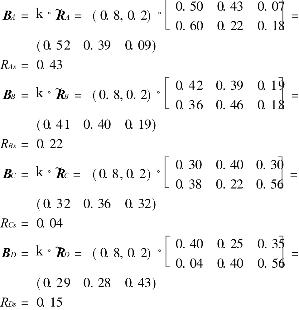
The results indicate that the order of range value is:A>B>D>C,namely the sequence of these four processing parametersimpacting on the quality of parts is ABDC.Fig.1 shows the relationships between different levels of impact factor and SNR of the examined index.Bigger SNR value shows that real size of parts is closer to theoretical value,namely,higher dimensional accuracy.Therefore,the optimal combination of these four processing parameters is A1B1C2D3.
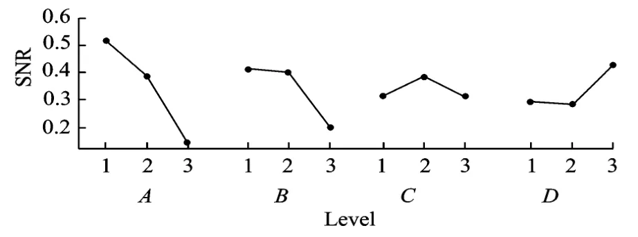
Fig.1 Effect of different levels on SNR
4 PROCESSING PARAMETER OPTIMIZATION
4.1 Wire-width compensation
For specific solidified wire-width,when the value of wire-width compensation is 1/2 of solidified wire-width,the accuracy of the parts is the highest.That is,the greater the value of the wire-width compensation deflecting 1/2 of thesolidified wire-width is,the greater the size error of the parts is.In this experiment the diameter of the nozzleis 0.3 mm,and the theoretical value of the wire-width compensation is in 0.15 mm range vicinity.When wire-width compensation takes the first level,that is 0.17 mm,the valueis close to the theory valueand SNRis the biggest,so the wire-width compensation checking the first level is the best for size error.
4.2 Extrusion velocity and filling velocity
When no considering interference and random error,the warping deformation increases and SNR decreases correspondingly with the increase of ex trusionvelocity(v e)and filling velocity(v f).Size error affects th read-width through the changes of extrusion velocity and filling velocity.When thread-width matches the wire-width compensation,the dimensional accuracy is the highest.
4.3 Layer thickness
Experimental results indicate that layer thickness has littleinfluence on the size error for rectangular parts,but has great influence on the warpage deformation. The greater the layer thickness is,the smaller the warpage deformation is.This conclusion is coincides with analytical result of the mathematical model established in Ref.[9].
The rangevalues of indexes can becalculated when optimized parameters are obtained.After that,the com prehensiveimpacts of the processing parameters on dimensional accuracy and warpage deformation are analysized respectively,and then the optimal combination scheme of the processing parameters and their sequence impacting on the quality of parts can be determined.Finding out the major factors impacting the quality of parts and strictly controlling them during the course of fabrication can achieve the purpose of improving the quality of parts.
5 CONCLUSIONS
(1)The significant influence order of the four processing parameters on the dimensional accuracy and war page deformation is wire-width compensation,extrusion velocity,layer thickness,and filling velocity.
(2)The combinations of processing parameters for improving parts accuracy and reducing war page deformation are different,which needs to integrally consider indicators of the two indexes to make the processing parameters match the best value.
(3)Under the experimental conditions that wire-width compensation is 0.17 mm,extrusion velocity 20.00 mm/s, filling velocity 30.00 mm/s,and layer thickness 0.25 mm,the dimensional accuracy of the produced block parts reaches±0.07,meanwhile,the warpage deformation is less.
[1] Huang Xiaomao,Ye Chunsheng,Mo Jianhua,et al.Slice data based support generation algorithm for fused deposition modeling[J].Tsinghua Science and Technology,2009,14(S1):223-228.
[2] Wang Tian ming,Xi Juntong,Jin Ye.Prototype surface microprecision in fused deposition modeling process[J].Chinese Journal of M echanical Engineering,2007,20(1):100-106.
[3] Gunawan S,Azarm S.Multi-objective robust optimization using asensitivity region concept[J].Structural and Multidisciplinary Optimization,2005,29(1):50-60.
[4] Wang Gengxin,Han Zhijun.Relationship between SN ratio and quality loss of product in case of L TB and STB[J].Mechanical Science and Technology,2009,19(2):236-238.(in Chinese)
[5] Shen Bangxing.Experimental design and engineering application [J].Beijing:Chinese Measurement Press,2005.(in Chinese)
[6] Zhang Jianfeng,Peng Anhua.Decision-making of slicing scheme in fused deposition modeling process based on analytical hierarchical process[J].Transactions of Nanjing University of Aeronautics& Astronautics,2010,27(2):125-130.
[7] Pan Posong.The design of indicators to optimize based on the orthogonal trial injection technology[J].Journal of Zhejiang University of Technology,2007,35(3):305-312.(in Chinese)
[8] Hsu Chia wei,Hu Allen h,Chiou Cherngying,et al.Using the FDM and ANP to construct a sustainability balanced scorecard for the semiconductor industry[J].Expert Systems with Applications,2011,38:12891-12899.
[9] Peng Anhua,Zhang Jianfeng.The middle layer of fuss deposition modeling parts stress and warpage deformation study[J].Journal of Zhejiang University of Technology,2007,16(2):16-19.(in Chinese)
杂志排行

Transactions of Nanjing University of Aeronautics and Astronautics的其它文章
- GRIDLESSMETHOD FOR UNSTEADY VISCOUSFLOWS
- NOVEL WEIGHTED LEAST SQUARESSUPPORT VECTOR REGRESSION FOR THRUST ESTIMATION ON PERFORMANCE DETERIORATION OF AERO-ENGINE
- APPLICATION OF HYBRID AERO-ENGINE MODEL FOR INTEGRATED FLIGHT/PROPULSION OPTIMAL CONTROL
- LINEAR ULTRASONIC MOTOR USING LONGITUDINAL VIBRATION
- VIBRATION CHARACTERISTIC INVESTIGATION OF COUNTER-ROTATING DUAL-ROTOR IN AERO-ENGINE
- CNC SYSTEM OF FLEXIBLE FIXTURE IN AIRCRAFT COMPONENT MANUFACTURING AND ASSEMBLY