LINEAR ULTRASONIC MOTOR USING LONGITUDINAL VIBRATION
2012-10-08WangYinHuangWeiqing
Wang Yin,Huang Weiqing
(College of Aerospace Engineering,Nanjing University of Aeronautics and Astronautics,Nanjing,210016,P.R.China)
INTRODUCTION
Ultrasonic motors are energy transformation devices that transform electric energy into mechanical energy utilizing the inverse piezoelectric effect.In this process,alternating voltage signals with ultrasonic frequencies are applied to piezoelectric ceramics to excite certain vibration modes of stator,whose vibrating energy is cumulated to push a rotor or mover by friction.Th eir features such as fast response,high resolution,non magnetic,and low noise,make ultrasonic motors be good solutions for a large range of modern industry requirements[1-2].In linear ultrasonic motors(LUSM),vibrating energy of stator is directly transformed into motion energy of mover without any gear systems,so the application of LUSM makes a system smaller and simpler[3].
The stator which is usually composed of elastic body and piezoelectric ceramics is the key component of a linear ultrasonic motor.Since the operation of stator utilizes resonance of elastic body excited by piezoelectric ceramics,the construction type between the elastic body and thepiezoelectric ceramics influents theperformanceof motor a lot.According to construction type of elastic body between piezoelectric ceramics,ultrasonic motor can be classified into sandwich typeand sticking type.In the sticking type,piezoelectric ceramics are bond onto the surface of elastic body by thin layers of bond,where the d31 effect of piezoelectric ceramics is used and vibrating energy of piezoelectric ceramics is transferred by shear stress,so there is a problem of aging and shedding in the bond layer.Besides,the bonding layer consumes energy of vibrating piezoelectric ceramics,which lowers the efficiency of motor.In the sandwich type, piezoelectric ceramics are mechanically gripped by elastic body and the d33 effect of piezoelectric ceramics is utilized to transfer energy by normal stress.Since the piezoelectric constant d33is bigger than d31,the sandwich typewithout bond layer has higher reliability and efficiency[4-8].
There are two typical sandwich type linear ultrasonic motors, V shape[9-11]and shaking beam[12-13]. Their common feature is that their stators have two longitudinal vibrators,so they have high thrust force.However,in the V shape LUSM,two longitudinal vibrators are connected at the end with a right angle,which inevitably causes bending vibration of vibrators and lowers the efficiency of transducer.Besides,the V shape structure enlarges lateral dimension of stator,which makes the minimization of LUSM difficult.Shaking beam LUSM forms the elliptical motion of driving foot by a shaking beam pushed by two parallel longitudinal vibrators.Its structure is smaller than V shape,but the bending mode of the beam is excited simultaneously.This also reduces the efficiency.
In order to find a solution to minimizing the structure of LUSM adopted two longitudinal vibrators and avoiding the decrease in efficiency caused by disturbing modes,LUSM with two longitudinal vibrators is proposed in this paper.The feature of LUSM is that a semi-circumferential structure is used to link two longitudinal vibrators with varying sections.
1 CONSTRUCTION OF STATOR
The structure of LUSM is shown in Fig.1.The stator is composed of two longitudinal vibrators with varying section.These two vibrators are connected by a semi-circumferential structure whose middle driving foot is located.The stator is pressed onto the mover by a guiding spring system.
Dimensions of the stator and the polarization directions of piezoelectric ceramics are marked in Fig.2.There are two groups of piezoelectric ceramics with four pieces in each group.All parts of the stator are fastened together by two bolts under proper pressure.
2 OPERATING PRINCIPLE
In LUSM,there are two energy converting procedures,including vibration exciting proce-
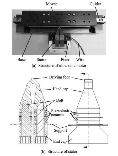
Fig.1 Structure of LUSM
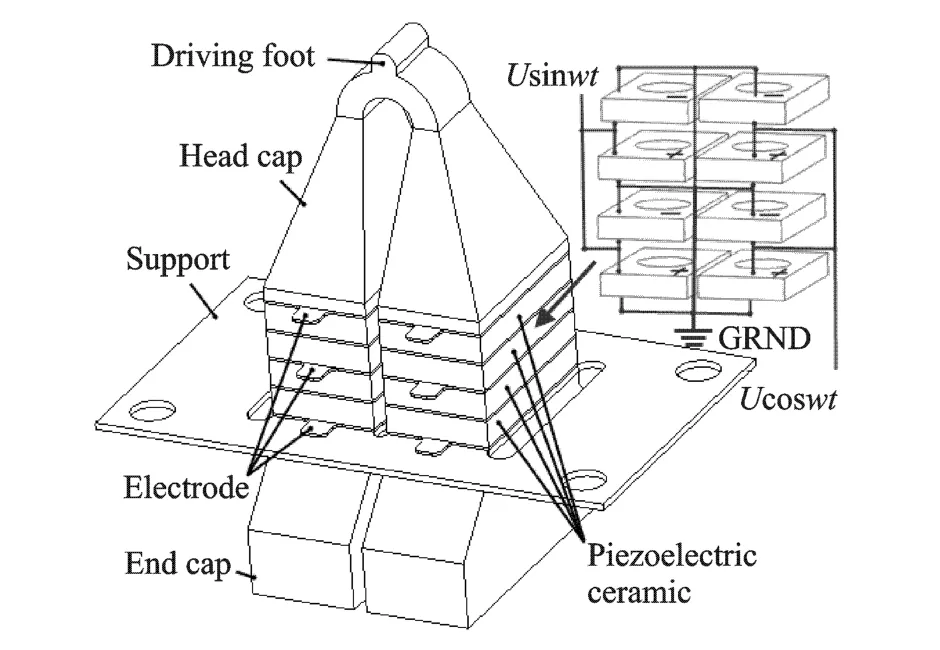
Fig.2 Polarization of piezoelectric ceramics and its wire connection
dure and frictional driving procedure.In vibration exciting procedure,voltage signals with ultrasonic frequencies are applied to piezoelectric ceramics to excite vibration modes of stator,thus forming elliptical motion of driving foot.In the frictional driving procedure,vibration energy of stator is transferred to kinetic energy of the unidirectional motion of mover through frictional force between driving foot and mover[14].Thus it is important to choose proper vibration modes of stator to make its driving foot vibrate elliptically.
The resonance of stator is used during the operation process of LUSM and the chosen two modes shown in Fig.3 are excited simultaneously.One mode(called LL mode in the follows)in which two vibrators stretch and compress together causes the normal vibration of driving foot,while the other mode(called LSmode in the follows)in which two vibrators stretch and compress alternately causes the lateral vibration of driving foot.
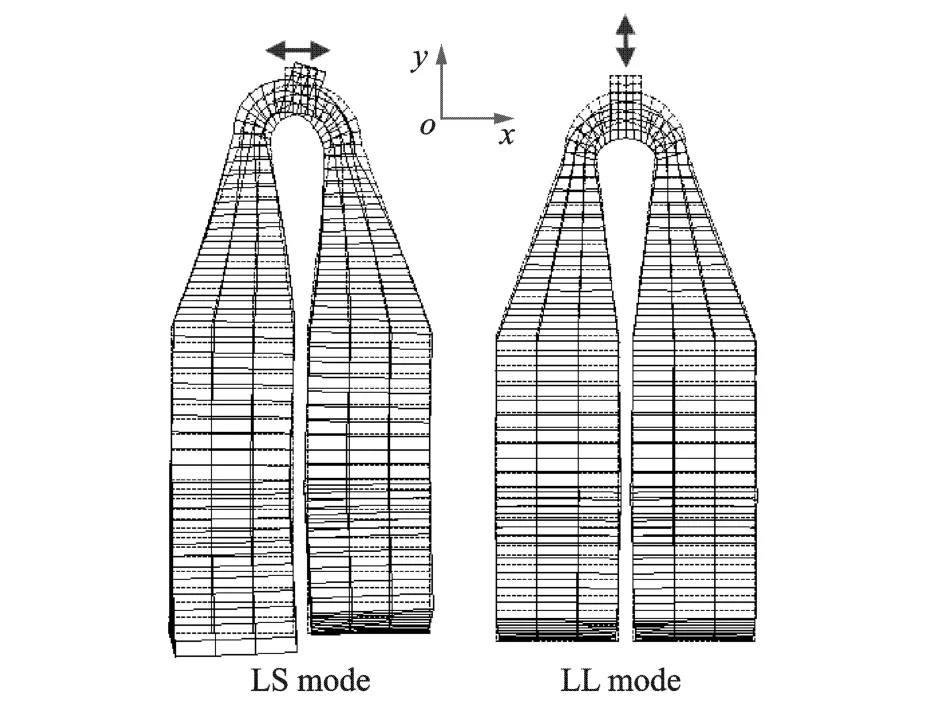
Fig.3 Two working modes of ultrasonic motor
If the origin of coordinate system shown in Fig.3 is moved to the top point of driving foot,when the LL modeis excited the motion trajectory of the particle on top of driving foot can be formulated as

where Ax is the amplitude of vibration along x-axis and k thevibration frequency.Likewise,when the LSmode is excited its motion trajectory can be formulated as

where Ay is theamplitude of vibration along y-axis.
When the above two modes are excited with phase difference ofπ/2 simultaneously,the motion trajectory of the particle can be formulated as

Eq.(3)can be simplified by substituting k t,shown as

Eq.(4)is an ellipse equation,which states that when LL and LSmodes are excited simultaneously the particles in driving foot elliptically vibrate.
When two groups of piezoelectric ceramics are applied with two sinuous voltage signals with the same frequency and a phase differenceπ/2 respectively(Fig.2),the LL and LSmodes of stator are excited with a vibration phase difference π/2.As a result,the normal and lateral vibration of driving foot has a phase difference ofπ/2,that is,the driving foot vibrates in an elliptical trajectory,as shown in Fig.4.A mover is pushed to move linearly with the driving foot pressing onto its surface.If one of the voltage signal phases is reversed,the mover changes its motion direction.
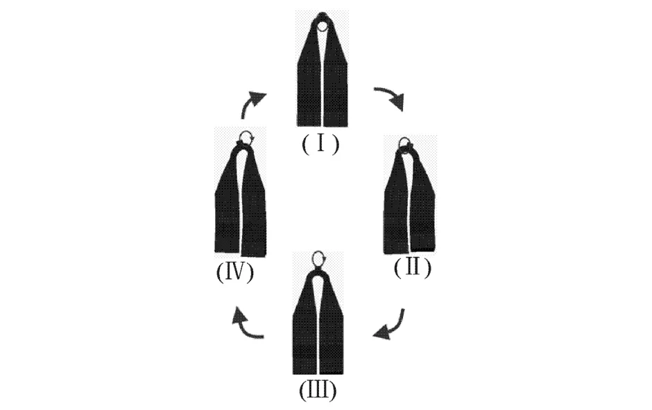
Fig.4 Operation of stator in one period
3 STRUCTURE DESIGN
According to the operation principle,the LL and LSmodes must be excited simultaneously at the same frequency.This can be realized by adjusting structure parameters and this process is called mode degeneration.To decrease the influence of support on the vibration modes,the support is located at longitudinal vibration nodes of transducer,which is a thin plate sandwiched by stator components as shown in Fig.2.In this design,eight piezoelectric ceramics with 14 mm length,8 mm width and 2 mm thickness are used to excite longitudinal vibration of stator.In the center of each piezoelectric ceramic plate,thereis a hole with diameter of 5 mm for the convenience of assemblage.
Parametric finite element model of stator is built using commercial FEA software ANSYS.Dimensions of stator are shown in Fig.5.Bounce is chosen to be thematerial of elastic body and element type solid 45 is selected to simulate the elastic body.Some simplifications such as the neglect of electrodes and the support are made.
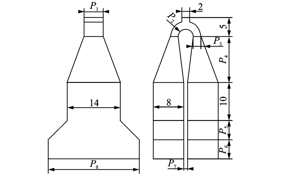
Fig.5 Parametric model of stator
Sensitive analysis is conducted to find sensitive structure parameters to degenerate operation modes of stator.By modifying the parameters of finite element model with 0.1 mm increase,changes of two mode frequencies are obtained as shown in Fig.6.
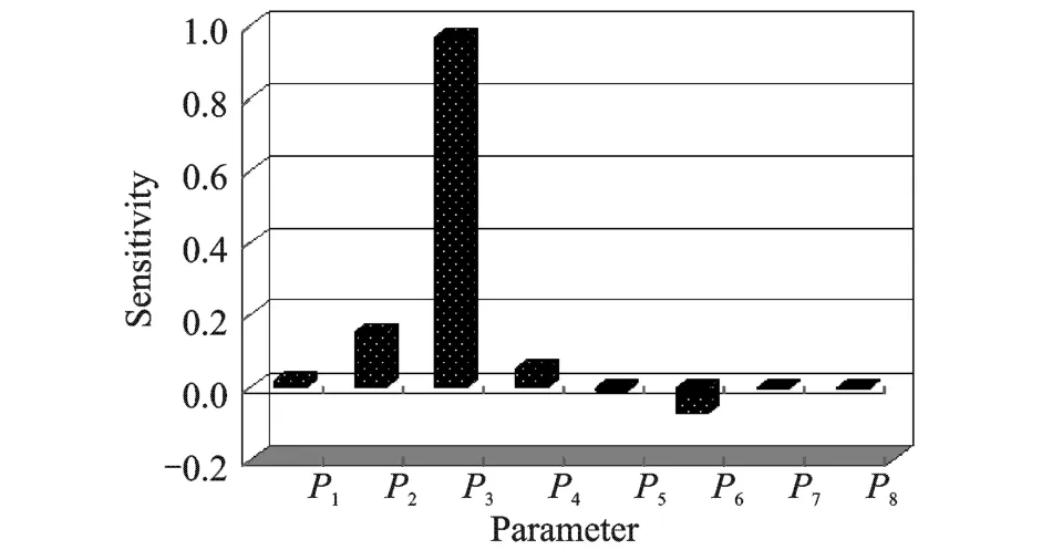
Fig.6 Sensitive results of parameters
From Fig.6,parameters P2,P3 and P6 are more sensitive.Therefore it is available to eliminate the frequency difference of two operation modes by adjusting these parameters.
4 MEASUREMENTS AND ANALYSIS
Using finite element analysis,dimensions and materials of the stator are selected.A prototype with bounce(QSn6.5-0.4)elastic body and PZT8 of 14 mm× 8 mm× 1 mm is fabricated.The mover is a linear slider coated with Al2 O3 ceramic,as shown in Fig.7.
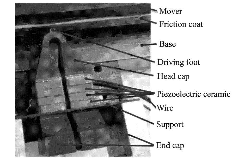
Fig.7 Prototype picture
Modal test of stator is conducted using the laser Doppler vibrometer,which can obtain the shape of vibrating surface.To identify two operation modes,the laser beam is pointed on the two end cap surfaces.In LL mode,two end cap surfaces vibrate with thesame pace whilein LSmode they vibrate reversely,as shown in Fig.8.Two operation modes are found at 48.69,48.90 k Hz,as shown in Fig.9.
Performance test set is shown in Fig.10.The relations between speed and frequency,speed and thrust are studied.
According to Fig.10,it is concluded that the closer exciting frequency is to mode frequency,the faster mover moves.When the exciting frequency is lower than mode frequency,the speed can increase very fast.Then the speed decreases slowly with the increase of exciting frequency.
5 CONCLUSIONS
(1)A novel sandwich type linear ultrasonic motor utilizing longitudinal vibration is proposed in this paper.Its operation principle is analyzed and the motion trajectories of driving tip are formulated as an ellipse equation.
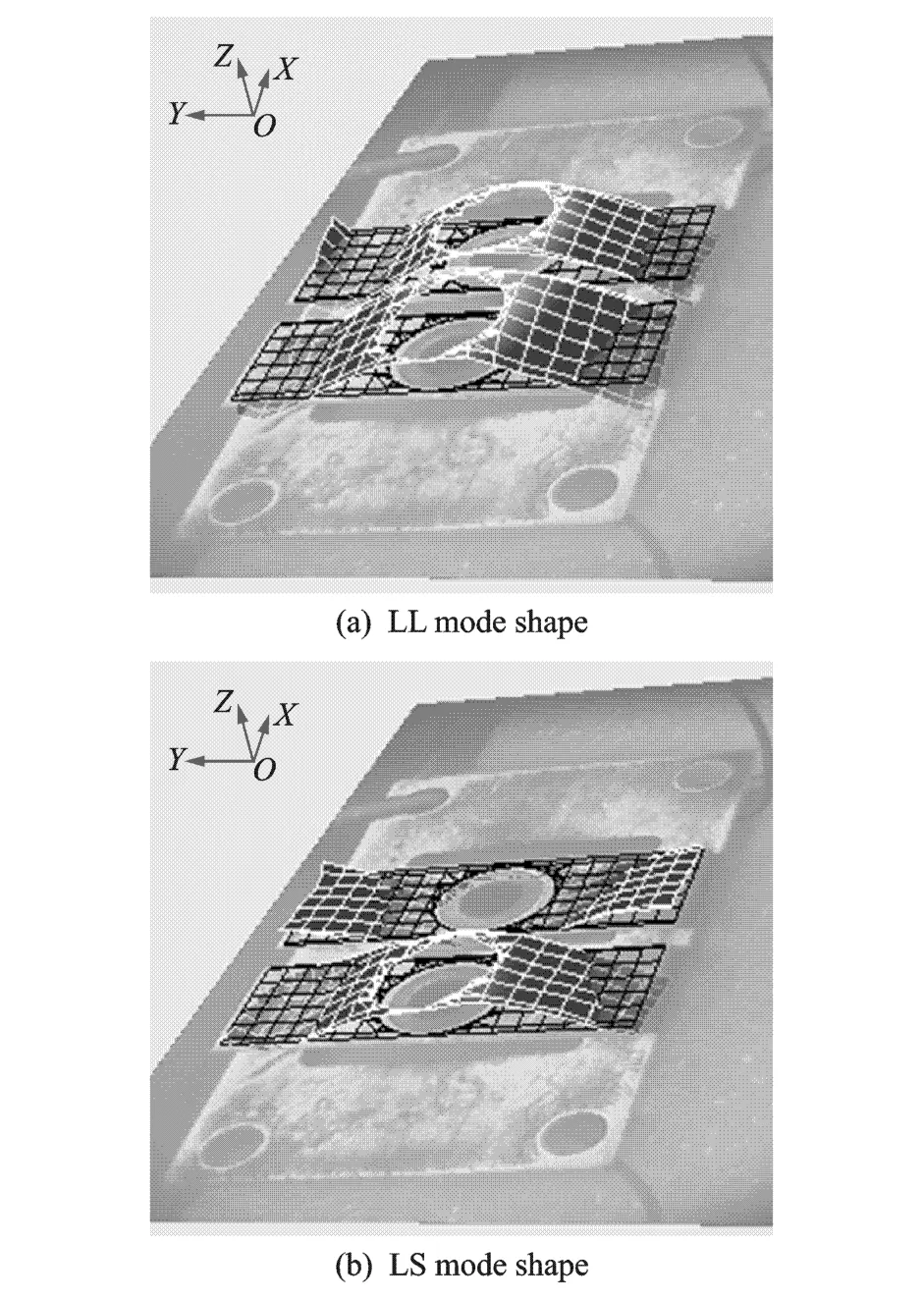
Fig.8 Two mode shapes of stator
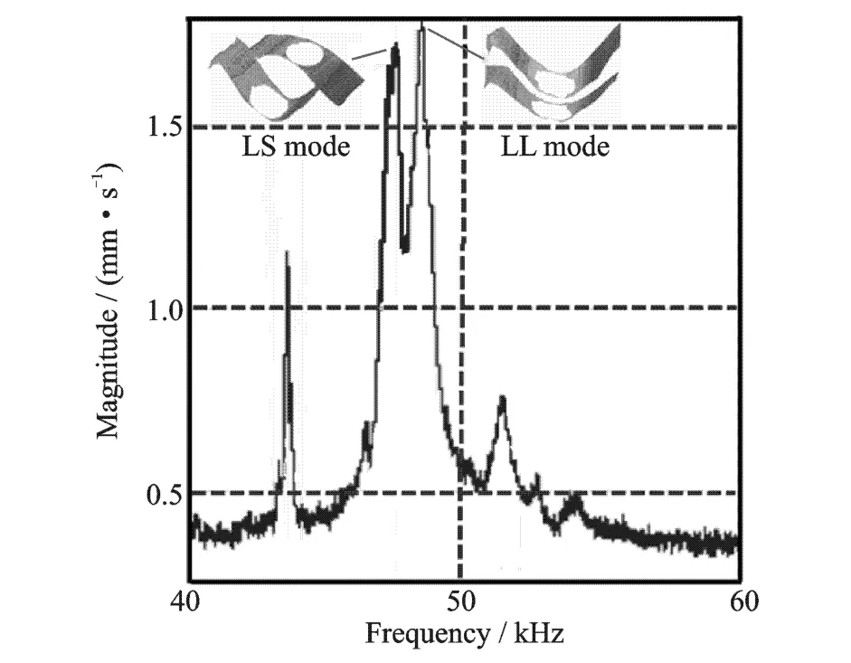
Fig.9 Harmonic response of stator
(2)According to sensitive analysis results obtained by means of finite element method,the structureof motor is designed and its prototypeis fabricated.Prototype test and performance statistics of motor show that the motor can afford load of 10 N at the speed of 100 mm/s.
(3)Since the friction pair of stator and mover can be optimized and frequency difference between two working modes can be further decreased,motor performanceis improved.
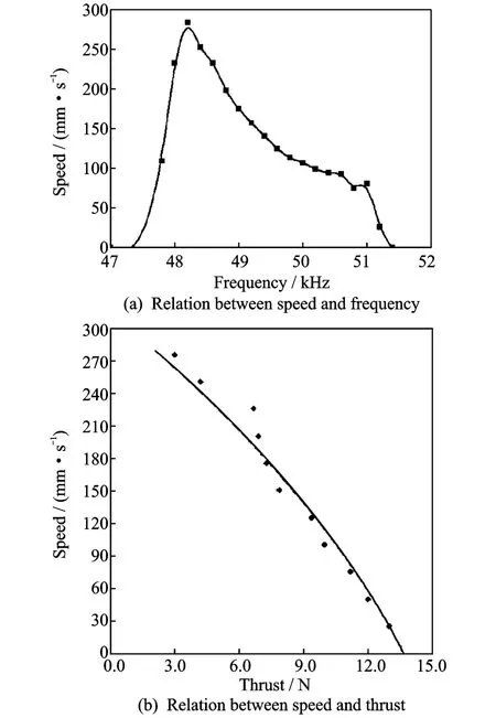
Fig.10 Performance test results
[1] Zhao Chunsheng.Ultrasonic motors: Technologies and applications[M].Beijing:Science Press,2007:6-7.(in Chinese)
[2] Zhang Jiantao,Huang Weiqing,Zhu Hua,et al.Lead screw linear ultrasonic motor using bending vibration modes[J].Transactions of Nanjing University of Aeronautics&Astronautics,2009,26(2):89-94.
[3] Shi Yunlai,Zhang Hanlei,Li Yubao,et al.Two DOF positioning stageusing linear ultrasonic motors[J].Transactions of Nanjing University of Aeronautics&Astronautics,2008,25(3):161-168.
[4] Asumi K,Fukunaga R,Fujimura T,et al.Miniaturization of a V-shape transducer ultrasonic motor[J].Japanese Journal of Applied Physics,2009,48(7):1-5.
[5] Li Zhirong,Liu Junbiao,Huang Weiqing,et al.New type of linear ultrasonic motor with two degrees of f reedom using longitudinal and bending mode[J].Transactions of Nanjing University of Aeronautics&Astronautics,2004,21(1):7-12.
[6] Hemsel T,Mracek M,Wallaschek J,et al.A novel approach for high power ultrasonic linear motors[C]//2004 IEEE Ultrasonics Symposium.Montreal,Canada:IEEE,2004:1161-1164.
[7] Liu Yingxiang,Chen Weishan,Liu Junkao,et al.A high-power linear ultrasonic motor using longitudinal vibration transducers with single foot[J].IEEE Transactions on Ultrasonics Ferroelectrics and Frequency Control,2010,57(8):1860-1867.
[8] Wang Yin,Jin Jiamei,Huang Weiqing.A novel rotary ultrasonic motor using an in-plane traveling wave[J].Journal of Korean Physical Society,2010,57(4):882-885.
[9] Kurosawa M K,Kodaira O,Tsuchitoi Y,et al.Transducer for high speed and large thrust ultrasonic linear motor using two sandwich-type vibrators[J].IEEE Transactions on Ultrasonics,Ferroelectrics and Frequency Control,1998,45(5):1188-1195.
[10]Dong Yang,Yao Zhiyuan.Research on V-shapelinear ultrasonic motor based on amplitude amplifier pole[J].Piezoelectrics& Acoustooptics,2009(5):685-687.(in Chinese)
[11]Shi Yunlai,Li Yubao,Zhao Chunsheng.Operating principle analysis of a V-shape linear ultrasonic motor[J].Piezoelectrics& Acoustooptics,2008(6):772-775.(in Chinese)
[12]Lee K,Lee D K,Borodinas S,et al.Analysis of shaking beam actuator for piezoelectric linear ultrasonic motor[J].IEEE Transactions on Ultrasonics,Ferroelectrics and Frequency Control,2004,51(11):1508-1513.
[13]Borodin S,Kim JD,Kim H J,et al.Nano-positioning system using linear ultrasonic motor with"shaking beam"[J].Journal of Electroceramics,2004,12(3):169-173.
[14]Jin Jiamei,Zhang Jianhui,Zhao Chunsheng.Elliptic motions on modal conversion ultrasonic motors[J].Transactions of Nanjing University of Aeronautics&Astronautics,2008,25(4):262-265.
杂志排行
Transactions of Nanjing University of Aeronautics and Astronautics的其它文章
- GRIDLESSMETHOD FOR UNSTEADY VISCOUSFLOWS
- NOVEL WEIGHTED LEAST SQUARESSUPPORT VECTOR REGRESSION FOR THRUST ESTIMATION ON PERFORMANCE DETERIORATION OF AERO-ENGINE
- APPLICATION OF HYBRID AERO-ENGINE MODEL FOR INTEGRATED FLIGHT/PROPULSION OPTIMAL CONTROL
- VIBRATION CHARACTERISTIC INVESTIGATION OF COUNTER-ROTATING DUAL-ROTOR IN AERO-ENGINE
- CNC SYSTEM OF FLEXIBLE FIXTURE IN AIRCRAFT COMPONENT MANUFACTURING AND ASSEMBLY
- EXPERIMENTAL STUDY OF HTC FOR FILM COOLING OF PARALLEL-INLET HOLES
