VIBRATION CHARACTERISTIC INVESTIGATION OF COUNTER-ROTATING DUAL-ROTOR IN AERO-ENGINE
2012-10-08FengGuoquanZhouBaizhuoLuoGuihuo
Feng Guoquan,Zhou Baizhuo,Luo Guihuo
(1.School of Mechanical Engineering,Dalian University of Technology,Dalian,116024,P.R.China;2.Shenyang Aero-Engine Research Institute,Aviation Industry Corporation of China,Shenyang,110015,P.R.China;3.College of Energy and Power Engineering,Nanjing University of Aeronautics and Astronautics,Nanjing,210016,P.R.China)
Nomenclature
y Vertical displacement vector
z Horizontal displacement vector
m Mass matrix of rotor system
k Stiffness matrix of rotor system
k Angular velocity of spin
K Angular velocity of whirl
g Moment of inertia matrix
p Complex variables,p=y+j z
p0Amplitudedisplacement vector
λ Rotational speed ratio,λ=k/K
INTRODUCTION
With the development of aero-engine design technology,the thrust-weight ratio of the aeroengine has changed from 8(such as F100,F110,АЛ-31Φ,etc.)to 10.In America and Europe,aero-engines with the thrust-weight ratio as 10 have been put into practical use(such as F119 aero-engine used in F22 fighter,EJ200 aero-engine used in EJ2000 fighter).To pursue high thrust-weight ratio,the structure of counter-rotating dual-rotor usually was adopted in the rotor system for the advanced aero-engines. The counter-rotating dual-rotor system in the aero-engines has many advantages due to the high and low pressure rotors rotating reversely.For example,gyroscopic moment,reaction forces of supports and forces conveyed to the aircraft can be greatly reduced.The maneuverability and agility of the aircraft can be improved and the aerodynamic torque acting on the burning case opposite directions is lower.Due to the reverse rotation of the counter-rotating dual-rotor system,it becomes possible that the system is adopted in the counter-rotating turbine design technology.The guide vane of low pressure turbinein the aero-engine can be removed or simplified in order to reduce the structural weight and increase the thrust-weight ratio.Therefore,the aero-engines with counter-rotating dual-rotor have attracted great concerns for modern advanced military aeroengines that require high thrust-weight ratio.The counter-rotating dual-rotor system has been widely used in modern aero-engines(such as
E-mail:feng2004606@163.com F119,F135,F120,F136,RB199,Trent900,GE-NX,etc.)[1-10]and becomes an irresistible technique for increasing the high thrust-weight ratio in aero-engine design process.
The counter-rotating dual-rotor system in modern advanced aero-engines is usually supported with five bearings.The low-pressure rotor adopts 1-1-1 supporting program,and the highpressure rotor adopts 1-0-1 supporting program.Sometimes the strong rigid high-pressure rotor is supported on the weak rigid low-pressure rotor through the journals between shafts[11-12],shown as Fig.1.
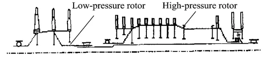
Fig.1 Diagram of dual-rotor engine with five bearings
The structure in Fig.1 looks simple and has fewer bearing components. However,as the high-pressure rotor bears on the bearing between shafts,the vibrations of high-and low-pressure rotors are coupled and interacted,and the coupling is further enhanced by reverse rotation.Therefore,the vibration characteristics of the counter-rotating dual-rotor in the aero-engines are more complex than thosein normal rotor system.For example,the critical speeds are decreased and the forward and backward whirlings of the rotor system turn out to be rather difficult to distinguish. To solve the vibration of the counter-rotating dual-rotor system,traditional vibration analysis methods are lack of efficiency and also difficult to undertake the further optimization design.Therefore,it is a great challenge on investigation of vibration and dynamics design technology of the dual-rotor aero-engines.
Currently,most research on rotor dynamics of aero-engines concentrates on the dual-rotor system.Since 1996,Wei Deming,et al[13-14]have used transfer matrix method and modal synthesis method to study responses of the aero-engine rotor system in the thermal bending steady state,critical speed of the multi-rotor bearing system,and unbalance responses.Feng Guoquan,et al[15]investigated the vibration characteristics of rotor system with initial bending.Feng Xinhai,et al[16]calculated the critical speed of the dual-rotor system on account of bearing between shafts.However,there is no research about the vibration characteristics of the counter-rotating dual-rotor.
Research on rotor dynamics of dual-rotor system started in 1990s in China.Zhang Lianxiang,et al[17]first used the overall transfer matrix method to study the dynamic characteristics and unbalanced responses of counter-rotating dual-rotor system.The research showed that the gyroscopic moment was the main influence factor between counter-rotating and co-rotating dual-rotor systems.Luo Guihuo[18],Chen Bin[19]experimentally studied rotor dynamic characteristics about the counter-rotating and co-rotating of a dual-rotor system using the dual-rotor test rig.Because of the slight difference of the rotating speed between two rotors, the differences between counter-rotating and co-rotating are not significant and mainly liein transient responses.
In this paper,the analysis method for vibration characteristics of counter-rotating dual-rotor system is proposed.Solving sequence of vibration characteristics is developed through the DMAP tool based on MSC.NASTRAN platform.Thevibration of counter-rotating dual-rotor in an aeroengine is studied and the influence factors of vibration characteristics and vibration performances are discussed.
1 ANALYSIS THEORY AND METHODS
1.1 Rotor dynamics anlysis
There are many monographs about finite element method(FEM)used to analyze rotor dynamics[20-23]. The aero-engine, compared with other rotating machinery,has some special features.Because of high rotating speed,rolling bearings are usually adopted and stiffnesses of rotor and support are isotropy.Without considering influences of squeeze film damper(SFD),the ro-tor dynamics of aero-engines has the characteristics of isotropic support stiffness,which is the assumption used by internal and abroad scholars for rotor dynamics design[22-23]of aero-engines.
From Ref.[22],without considering damping,the motion equation of rotor dynamics can be w ritten as

Coordinate system definition is shown in Fig.2.
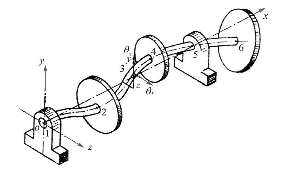
Fig.2 Coordinate system definition
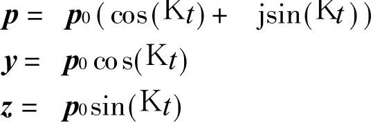
Under conditions of symmetric supporting stiffness,which means k y=k z=k,Eq.(1)can be further simplified. Assume p=y+ j z,then Eq.(1)can be rewritten as

Eigenvalues of Eq.(2)are pure imaginary,but eigenvectors are real vectors.Assume p=p0ejKt,then the characteristic equation is

Therefore,we have
When K>0,phase difference between y and z isπ/2,the corresponding direction vector of precession is the same with the x-axis,which means forward whirling.When K<0,phase difference between y and z is-π/2,the corresponding direction vector of precession is opposite to the x-axis,which means backward whirling.Therefore,the imaginary parts of the eigenvalues determine the whirling directions.
Furthermore,assume k=λK,Eq.(3)can be written as
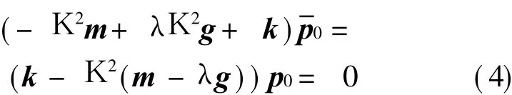
In this case,the system mass matrix m is replaced by(m-λg),and the gyro eigenvalue problem is converted to real eigenvalue problem.Though the mass matrix(m-λg)is symmetric,it is not necessarily positive definite.The eigenvalues of K2> 0 correspond to the forward whirling withλ,andλ=1 corresponds to critical speed.The eigenvalues of K2<0 are meaningless,should be removed.
Motion Eq.(2)can be rewritten as
The aforesaid conclusion can be extended to systems in which the speed K i is not exactly same(such as multi-rotor system).Without losing generality,the dual-rotor system is taken as an example,then Eqs.(2,5)can be written as

The sign of theimaginary part of eigenvalues of Eq.(6)determines the direction of whirling.However,when K> 0,the corresponding whirling direction is the same with rotor steering for Ki> 0,and when K< 0,the direction is the same with rotor steering for K i<0.In Eq.(7),eigenvalues of K2>0 correspond to the forward whirling withλ,andλ=1 corresponds to the critical speed.The eigenvalues of K2<0 are meaningless and should be canceled.It is noticed that the rotor for the reference rotor speedλi=1 means synchronization whirling.
Typical rotating speed relationship of a dualrotor aero-engine between the low-and the highpressure rotors is shown in Fig.3,where W L is the low-pressure rotor speed,and W H the highpressure rotor speed.It can be simplified to two linear segments.One is 0—idle and the other is idle—take off.
According to Eqs.(6,7),two vibration analysis methods for counter-rotating dual-rotor system can be developed as follows.

Fig.3 Rotating speed relationship of dual-rotor aeroengine
1.2 Campbell graph method
Several pairs of rotating speed are selected according to the function curve of speed. In counter-rotating dual-rotor system,the rotating speeds of rotors have two opposite signs:possive sign and negative sign.The positive or negative sign of the speed is determined by same or opposite direction between the rotating axis vector and the rotor spin.
By solving Eq.(6),eigenvalues corresponding to different rotating speed pairs can be obtained.When K>0,the corresponding whirling direction is the same with the rotor rotating of K i>0,and when K< 0, the corresponding whirling direction is the same with the rotor rotating of K i<0.Drawing rotating speed relationship curve between the reference rotor(exciting rotor)and forward whirling(Campbell diagram),the point that the forward whirling curve intersects with the 45°ray is the forward whirling critical speed of the exciting rotor.
1.3 Ray method
Eq.(7)can besolved by selected speed ratios obtained by the rotating speed relationship curve between the non-exciting sourceand the reference rotor speed.Drawing the relationship curve between eigenvalues for K2> 0 andλi,and theintersection is the synchronous forward whirling critical speed of the reference rotor for counter-rotating dual-rotor system.
From the solution of Eq.(7),the rotation speed ratio of the reference rotor(exciting rotor)is taken asλ1=1 and the rotation speed ratio of another rotor(non-exciting rotor)λ2 is taken different values in working range.Drawing the rotation speed relationship curve between eigenvalues and the reference rotor,the intersection point is the forward whirling critical speed of reference rotor for the counter-rotating dual-rotor system.
Generally,the eigenvalues of Eq.(6)are complex numbers and the mass matrix of Eq.(7)is symmetric but not necessarily positive definite.Both equations are difficult to be solved with conventional methods.Based on MSC.NASTRAN platform,the DMAP tool is developed to solve eigenvalues of Eqs.(6,7).The Campbell diagram can be plotted and the ray method can be used to analyze the vibration characteristics of the counter-rotating dual-rotor engine.Taking a turbofan engine as an example,the vibration characteristics are analyzed.The turbofan engineis consisted of a counter-rotating dual-rotor system with great rotating speed ratio,as shown in Fig.1.
2.1 Results of Campbell graph method
Based on Campbell diagram method,the vibration characteristics of the counter-rotating dual-rotor engine are analyzed.The critical speeds excited by low-and high-pressure rotors are displayed in the Campbell diagram,as shown in Figs.4,5,where W is the resonance speed.

Fig.4 Campbell graph excited by low-pressure rotor
2 APPLICATION OF COUNTERROTATING DUAL-ROTOR ENGINE

Fig.5 Campbell graph excited by high-pressure rotor
From Figs.4,5,we can see that the rotor acting on the exciting source moves with forward whirling and theother rotor acting on the non-exciting source rotates with backward whirling in the counter-rotating dual-rotor system.Somefrequencies of whirling modes are degressive when the speed of reference rotor increases.It is obviously different from the co-rotating dual-rotor system.Such features are related to the mode shapes,mass distribution and so on.The first four mode shapes excited by low-pressure rotor are shown in Fig.6,and thefirst six mode shapes excited by high-pressure rotor are shown in Fig.7.
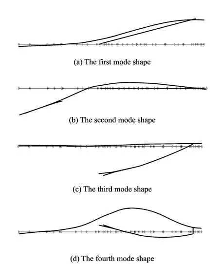
Fig.6 The first four mode shapes excited by lowpressure rotor

Fig.7 The first six modeshapes excited by high-pressure rotor
2.2 Results of Ray method
Based on the Ray method,the vibration characteristics of the counter-rotating dual-rotor engine are analyzed by the DAMP tool developed on the MSC.NASTRAN platform.The critical speeds of the counter-rotating dual-rotor engine excited by low-and high-pressure rotors are displayed in Ray diagram,as shown in Figs.8,9.

Fig.8 Ray diagram excited by low-pressure rotor exciting

Fig.9 Ray diagram excited by high-pressure rotor exciting
2.3 Results comparison
Critical speeds under the excitations of lowand high-pressure rotors respectively are also calculated by the transfer matrix method and further tested.Tables 1,2 list the critical speeds calculated by three methods and test results respectively.

Table 1 Critical speeds excited by low-pressure rotor r/min

Table 2 Critical speeds excited by high-pressure rotor r/min
As can be seen from Tables 1,2,the critical speeds calculated by Campbell diagram method,Ray method,transfer matrix method are consistent with the test results.Results show that the analysis results of vibration characteristics using the Ray method and the Campbell diagram areaccurate and the two methods can be used to design and analyze vibration characteristics of counterrotating dual-rotor aero-engines.
3 CONCLUSION
In this paper,the Ray method and the Campbell graph method are used to analyze critical speeds of counter-rotating dual-rotor system.The results show that both developed methods using DMAP tool on MSC.NASTRAN platform have sufficient engineering accuracy compared with test results,and they have great potential in practical engineering applications for vibration characteristic analysis and investigation as well as design of high thrust-weight ratio aero-engines with counter-rotating dual-rotor.
[1] Chen Guang,Hong Jie,Ma Yanhong.The structural design of aero gas turbine engines[M].Beijing:Beijing University of Aeronautics and Astronautics Press,2006.(in Chinese)
[2] Chen Guang.The design features of F119 engine[J].Aero Engine,2001(1):21-29.(in Chinese)
[3] Bonello P,Hai P M.A receptanceharmonic balance technique for the computation of the vibration of a whole aero-engine model with nonlinear bearing[J].Journal of Sound and Vibration,2009,324(2):221-242.
[4] Hai P M,Bonello P.An impulsive receptance technique for the time domain computation of the vibration of a whole aero-engine model with nonlinear bearings[J].Journal of Sound and Vibration,2008,318(3):592-605.
[5] Bonello P,Brennan M J,Holmes R.A study of the nonlinear interaction between an eccentric squeeze film damper and an unbalanced flexible rotor[J].Journal of Engineering for Gas Turbines and Power,2004,126(4):855-866.
[6] Wadia A R,James F D.F110-GE-129 EFE-enhanced power through low risk derivative thecnology[R].ASME 2000-GT-0578,2000:544-551.
[7] Mikhail G,Jean-Jacques S,Fabrice T,et al.Experimental and numerical investigations of a dual-shaft test rig with intershaft bearing[J].International Journal of Rotating Machinery,2007:1-12.
[8] Mikhail G,Jean-Jacques S,Fabrice T.Multi-dimensional harmonic balance applied to rotor dynamics[J].Mechanics Research Communications,2008,35(8):537-545.
[9] Ferraris G.Prediction of the dynamic behavior of non-symmetric coaxial co-or counter-rotating rotors[J].Journal of Sound and Vibration,1996,195(4):649-666.
[10]Wang W,Kirkhope J.Component mode synthesis for multi-shaft rotors with flexible inter-shaft bearings[J].Journal of Sound and Vibration,1994,173(4):537-555.
[11]Liu Changfu,Deng Ming.Structural analysis of aircraft engine[M].Xi′an:Northwestern Polytechnical University Press,2006.(in Chinese)
[12]Fang Cangde.Themanual of world aero engine[M].Beijing:Aviation Industry Press,1996.(in Chinese)
[13]Wei Deming,Ren Pingzhen,Yang Shenji.The critical speed and unbalance response computation of aircraft engine with multi-bearing rotor system[J].Gas Turbine Experiment and Research,1996(4):34-37.(in Chinese)
[14]Ren Pingzhen,Cai Weidong,Hu Bigang,et al.The research on the calculation method of the steadystate response of rotor thermal bending in aircraft engine[J].Gas Turbine Experiment and Research,1996(4):27-32.(in Chinese)
[15]Feng Guoquan,Zhu Zhigen.Vibration characteristics of the rotor system with original deformation[J].Aero Engine,2003,29(1):20-22.(in Chinese)
[16]Feng Xinhai,Chen Yunxi,Liang Jiantao,et al.A critical speed calculation considering the influence of inter-shaft flexibility[J].Journal of Foshan University:Natural Science Edition,2001,19(1):18-23.(in Chinese)
[17]Feng Guoquan, Yue Chengxi,Zhang Lianxiang.The tactical analysis of engine with counter-rotating dual-rotor system[J].Aero Engine,1993(5):43-48.(in Chinese)
[18]Luo Guihuo.Thevibration analysis and experimental study on counter-rotating dual-rotor system[D].Nanjing:Nanjing University of Aeronautics and Astronautics,1999.(in Chinese)
[19]Chen Bin.The computational analysis and experimental study on counter-rotating or forward-rotating dual-rotor system[D].Nanjing:Nanjing University of Aeronautics and Astronautics,1999.(in Chinese)
[20]Zhong Yie,Wang Zheng,He YanZong,et al.Rotor dynamics[M].Beijing:Tsinghua University Press,1987.(in Chinese)
[21]Gu Jialiu,Ding Kuiyuan,Liu Qizhou,et al.Rotor dynamics[M].Beijing: National Defence Industry Press,1985.(in Chinese)
[22]Zhang Wen.Rotor dynamics theory[M].Beijing:Science Press,1990.(in Chinese)
[23]Yan Litang,Zhu Zigen,Li Qihan,et al.Dynamic analysis of structural systems[M].Beijing:Beijing University of Aeronautics and Astronautics Press,1989.(in Chinese)
杂志排行
Transactions of Nanjing University of Aeronautics and Astronautics的其它文章
- GRIDLESSMETHOD FOR UNSTEADY VISCOUSFLOWS
- NOVEL WEIGHTED LEAST SQUARESSUPPORT VECTOR REGRESSION FOR THRUST ESTIMATION ON PERFORMANCE DETERIORATION OF AERO-ENGINE
- APPLICATION OF HYBRID AERO-ENGINE MODEL FOR INTEGRATED FLIGHT/PROPULSION OPTIMAL CONTROL
- LINEAR ULTRASONIC MOTOR USING LONGITUDINAL VIBRATION
- CNC SYSTEM OF FLEXIBLE FIXTURE IN AIRCRAFT COMPONENT MANUFACTURING AND ASSEMBLY
- EXPERIMENTAL STUDY OF HTC FOR FILM COOLING OF PARALLEL-INLET HOLES