An Analytical Model for Modulation in Passive UHF RFID Transponder
2011-12-05ZHOUYiLUOJingGUIJianghua
ZHOU Yi, LUO Jing, GUI Jiang-hua
(China Electronic Technology Group Corporation No.58 Research Institute, Wuxi 214035, China)
1 Introduction
In recent year, Ultra High Frequency Radio Frequency Identification (UHF RFID) has attracted more and more attentions for its potential diverse applications such as supply train management, public transport management and etc. However, RFID is still facing challenges of ultra low cost and power consumption[1].
Modulator is an important module in a RFID transponder. To reduce power consumption, backscattering modulation is used in modulator. The power efficiency and modulation efficiency are critical parameters for modulator design. Usually Amplitude-Shift-Keying (ASK) and Phase-Shift-Keying (PSK) are two main modulation types used in RFID transponder. PSK has a better power efficiency compared with ASK[2]. However, the design of antenna matching with PSK is much more complex. ASK modulation is adopted in most of literatures, but the power efficiency of ASK is not investigated systematically. In this paper an analytical model for ASK modulation is proposed.
Section II introduces the architecture of RFID frontend; Section III describes the operational principle of backscattering modulation; Section IV presents the analytical model for ASK modulation, and validated through simulation; Section V gives the conclusion of this paper.
2 RF Front-end Architecture
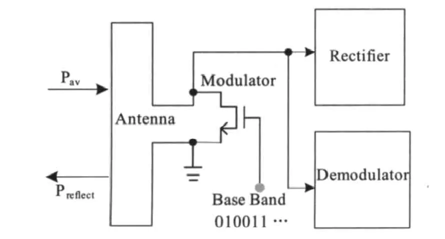
The simplified front-end architecture of a passive RFID transponder is illustrated in Fig.1, which composes of rectifier, modulator and demodulator. All modules are connected to folded dipole antenna in parallel. Rectifier transforms received EM energy into DC voltage, which is the power supply of other modules. Demodulator decodes RF signal from the reader. All these modules will interact with each other. For example, when modulator in operation,it will introduce a drop in voltage supply, which may disable the RFID transponder.

Fig.1 RF front-end architecture of UHF transponder
3 Operational Principles
High frequency signals will be partially reflected if the source impedance and load impedance don’t conjugated match, where source impedance and load impedance are antenna radiation impedance Zantand transponder input impedance Zinrespectively. The relationship of available power at antenna Pav, absorbed power Pinand reflected power Prefis given by:


From above equations we can see that backscattering modulation can be achieved through varying the transponder input impedance Zin.
In order to address how load impedances influence power efficiency and modulation efficiency, we assume the average duty cycle of digital signal is 50% for convenience, the average absorbed power is:

гS1、гS2are state1 and state2 reflection coefficients respectively. The useful backscattered signal power is[3]:

where i1and i2are the vectors of the current flowing between antenna and the chip for the two states,and antenna is assumed lossless. According to (4),|гS1|and|гS2|should be as small as possible for a better power efficiency; however, it may result in poor modulation efficiency if |ΔгS| is too small.

Fig.2 Polar coordinate of reflection coefficient
Fig.2 is polar coordinate diagram of reflection coefficient, it demonstrates there is a trade-off between Pinand Pback, and so how to obtain a proper гSis very important for modulator design.
4 Modulator Analysis
4.1 Modulator Model
In RFID, the communication type is half-duplex.Modulator and demodulator are not working simultaneously[4]. The effects of demodulator on transponder input impedance are negligible when modulator is working,so the load impedance is mainly determined by rectifier and modulator.
Prior to the design of modulator, the rectifier is optimized for better power efficiency. In our design, the opti-mized input impedance of rectifier is as follows:he input impedance of modulator needs to trade off between power efficiency and modulation efficiency. In our design, a single transistor is adopted to realize ASK modulation. If the transistor working as an ideal switch, the size of the transistor can be easily determined. For UHF application, the parasitic of the transistor is not negligible, which will affect the input impedance of the transistor greatly.
A high frequency model of the modulation transistor is depicted in Fig. 3. In the following, we will analyze the impedance of the transistor when digital signal is “1” or“0”, which corresponds to the two modulation sates. Modulation “ON” and modulation “OFF”.


Fig. 3 Model of modulator
(1) Modulation “ON” state: Given that the distance between the transponder and reader is around several meters, the input signal power level is low and the modulator transistor works at in triode region. The channel resistance and Cgdof the transistor are as follows:

Compared with Cgd, Cdbcan be neglected at triode region. The modulator input admittance could be approximately written as:

The total input admittance of the chip is:

For the antenna we adopt is loop dipole antenna, the radiation resistance is about 300Ω, substitute (10) and the figure 300Ωinto (3), one can get:

(2)Low Level Signal:The modulator transistor is off,whereis the overlap capacitor of gate and drain,is so small that it has little contribution the the total admittance,hencefor state2 is approximately to those of the rectifier:

So far,the expression of reflection coefficients for the two different states have been obtained,combining with(4)and (5),it shows clearly how to optimize the modulator.
4.2 Simulation Results
The model presented in this article has been verified through simulation. Fig. 4 gives гSof the rectifier, and Fig. 5 is гSof the whole chip for two different states.According to the two figures, one can get that гSof the chip for state2 is similar to that of the rectifier, while for state1,гSchanges a lot, which demonstrates that our model for the modulator accords well with the practical condition.

Fig. 4 гS of rectifier at Smith Chart
Fig. 6 shows the backscattering waveform of the modulator and rectifier output voltage, and both of them satisfy the system of EPC Class-1 Generation-2.
5 Conclusions

Fig. 5 гS of the whole chip for two states at Smith Chart

Fig.6 Backscattering waveform
This paper theoretically analyzes the operation principle of the backscattering modulator implemented in passive UHF RFID transponder, also it demonstrates how the input impedance influences the power and modulation efficiency. Based on this, a small signal model is presented for the long distance condition, which accords well with the practical cases. According to this model, optimization of the modulator can be achieved easily. The work is under fabrication and the measurements will be taken in the near future.
[1]Udo Karthaus, Matrin Fischer. Fully Integrated Passive UHF RFID Transponder IC with 16.7 μW Minimum RF Input Power[J]. IEEE Journal of Solid-State Circuits, 2003,38(10): 1602-1608.
[2]U. Kaiser et al..A Low-Power Transponder IC for High Performance Identification Systems[J]. IEEE Journal of Solid-State Circuits, 1995,3(3): 306-310.
[3]K. Finkenzeller. RFID Handbook[C]. Radio-Frequency Identifications Fundamentals and Applications, 2nd,New York: Wiley, 2003.
[4]G. DE Vita, G. Iannaccone. Design Criteria for the RF Section of Passive RFID Transponders[M]. unpublished,2004.
[5]A. Abrial, J. Bouvier, M. Renaudin,et al..A New Contactless smart card IC using an on-chip antenna and an asynchronous microcontroller[J].IEEE Journal of Solid-State Circuits,2001,36: 1101-1107.
