二氧化碳探测仪典型透镜支撑结构的设计及分析
2011-11-06梁彪,刘伟
梁 彪,刘 伟
(1.中国科学院长春光学精密机械与物理研究所,吉林长春130033; 2.中国科学院研究生院,北京100039)
1 Introduction
Carbon dioxide is a principal human-made greenhouse gas and the primary atmospheric component of the global carbon cycle.Human activities now emit more than 32 billion tons of carbon dioxide into the atmosphere each year,and the annual emission rate has increased steadily since the drawn of the industrial age.Over half of this carbon dioxide has been absorbed by natural sinks on land and in the ocean and the remainder stays in the atmosphere[1].Measurements made by the international carbon cycle science community have substantially improved our understanding of CO2sources and sinks,and their relationship to the climate change.Despite this progress,knowledge of the location of CO2sources and sinks,as well as how it concretely affects the climate evolution continues to be limited by a lack of a high precision global measurement of atmospheric CO2.Advances in carbon cycle science have intensified the need for accurate global observations of carbon dioxide from space.Therefore,many countries have made extensive researches on the measurements of CO2.In 2002,NASA selected the Orbiting Carbon Observatory(OCO)to return space-based measurementsto measure carbon dioxide sourcesand sinks[2].Japanese successfully launched the Greenhouse gases Observing Satellite(GOSAT)in 2009 to measure the global greenhouse gas and provided various data for the predication of global change.
Carbon dioxide detector is used to monitor carbon dioxide globally from space,it aims to the contribute to the international efforts to prevent global warming and find out where the carbon source is and how distributions it is.The carbon dioxide detector measures the intensity of sunlight that has reflected off earth surface and passed through the atmosphere to get spectrum information,then the greenhouse gas content is got by various inversion algorithms[3].For a high performance carbon dioxide detector,due to the hash working environments and high resolution requirement,it is important to design a appropriate opto-mechanical structure.One of the important aspects is the lens support structure design.Many new types of mirror structures have been proposed[4-6],but there are very few papers research on high performance lens's support structure[7-8].In this paper,based on the specifications of the biggest typical lens of carbon dioxide detector,a radial support structure for it has been proposed.To verify the new model,the performance under different conditions has been analyzed by using FEA methods.The results show that it satisfies requirements well and has many advantages compared with the general lens support structure.
2 General considerations in opto-mechanical design
One of the principles of structure design is to obtain the lightestmasswhile assuring the necessary strength and stiffness.The support structure must have enough strength and stiffness to bear the complicated dynamic load and impacting load.Structural design should be adequately rigid that the displacements of the interrelated components and the mechanical stresses imposed there on are smaller than the tolerable limits under all anticipated operational conditions.Fig.1 is the flow diagram for design phases of lens support structure.Deformations of lenses,housings,and other structural members do occur in the presence of thermal,acceleration,and other externally applied loads.Lens surface deformation and position error have a big influence on detector's performance,so it must be strictly controlled.To ensure the work quality,for the typical lens of the carbon dioxide detector,it is required to be assembled with extremely tight axial,tilt,and decentration tolerances.Alignment must be retained under operational levels of shock,vibration,and temperature variations.Furthermore,misalignments occurring during exposure to survival levels of these environments must be reversible.For general support structure,it can not meet these,so a new type of support structure must be developed to meet the requirements above and no to make the differential expansion ofmaterials caused by temperature changes affect lens tilt or centration.Fig.2 shows the optical structure layout of the detector.The main design specifications for typical lens in the support structure under all working conditions are as shown in Tab.1.
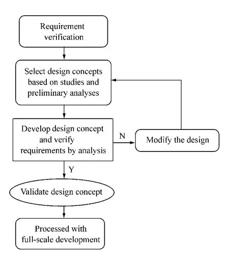
Fig.1 Flow diagram for design process
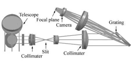
Fig.2 Optical layout of the detector
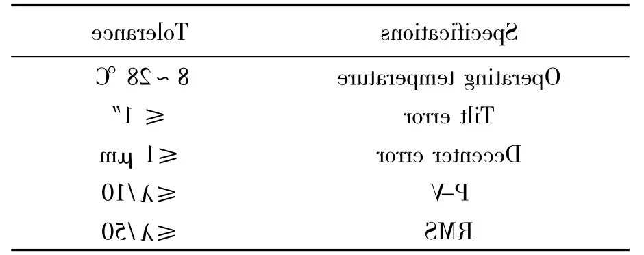
Tab.1 Specifications and tolerances for typical lens
3 Design of lens support structure
3.1 Lens mounting method and opto-mechanical interface
It is based on the application requirements of instrument to lens and lens size to select mounting methods.There are many mounting methods for lens.Burnished mounting is most frequently used with small lens.The cell material must be malleable rather than brittle.It is inexpensive,compact,and requires a minimum number of parts,but the mounting is permanent,removal of the lens without damaging it is extremely difficult.It is very easy to apply permanent stress to lens during the burnishing operation which would cause the decrease of profile accuracy.Another method is the threaded retaining ring mounting,it is widely used in the lens that can not be used with burnished mounting and radius more than 50 mm[9]. Compared with other mounting methods,the stress to lens is minimal and the mechanical reliability is high.In a typical mounting configuration,the main chief variable is the magnitude of applied force and the shapes of the opto-mechanical interfaces between the lens material and metal parts.Sharp corner interfaces and tangential interfaces are most widely used.Compared with sharp corner,easily made by the modern machining technology,the tangential interface tends to produce smaller contact stress in the lens for a given preload than the sharp corner interface.The lens radial flexure support structure uses threaded retaining ring and tangential interfaces based on above.
3.2 Structure design
A modular design is adopted for lenses of the detector,that each of these lenses is contained in it's own individual cell,then it is very convenient to alignment and maintenance.Lens material is silica,invar was chosen as the support structural material because of it's thermal expansion properties closely matching lens.The structures supporting lens would deform under the thermal effects,gravity load and externally applied loads.It is thus indispensable to isolate the optics to avoid subjecting them to undue stress[9].This is accomplished by mounting the optics in a statically determinate manner,using what is called a kinematic mount.A rigid body in space has six degrees of freedom:translation and rotation along each of three orthogonal axes.The body is fully constrained when each of these possible movements is singly prevented.If any one movement is constrained in more than one way,then the body will be deformed by the external forces.Kinematic mount is a mounting system which does not constrain more than six rigid-body degrees of freedom.When an optical element is mounted kinematically,the structure supporting can deform in response to a thermal load or changing gravity vector without affecting the optical figure,the optical element can move as a rigid body,but will not deform[10].One common form of kinematic mount for optical elements is the three point support as shown in Fig.3.The symbolsCRandCTin Fig.3 represent the spring constants(stiffness)of radial and tangential flexures.
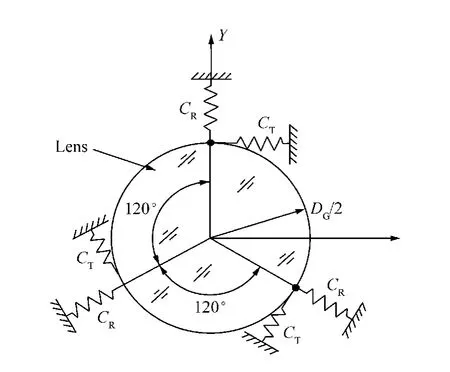
Fig.3 Schematic of three-point structure
Typically,the flexures are stiff tangentially and axially,soft radially.This configuration has the advantage of minimizing decenter errors even in the presence of large differential contractions between optical elements and their support structures.
Therefore the concept of the radial support structure for lens has been proposed in Fig.4 and Fig.5.Three outer convex surfaces are attached to barrel,three inner seats feature at 120 intervals which provide contact surfaces for lens,then six flexure modules have been formed.
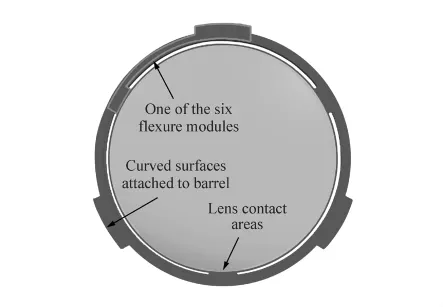
Fig.4 Example of lens radial support

Fig.5 3-D model of lens radial support structure
The equal compliances of the six radially oriented flexures keep the lens centered in spite of differential expansion with temperature changes,and allow the lens to decent during extreme shock and vibration exposure,yet return to the correct location after these dynamic disturbances have subsided.It also minimizes stress within the optic during such exposures,because it has isolated the optics from support structure.In order to relieve thermal stresses and preload the system in the direction of the axis,a single O-ring is placed on the surface.Fig.6 shows example of cell components.
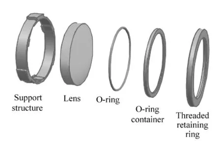
Fig.6 Cell components with radial support structure
4 Finite element analysis
To verify the model,the dynamic and static rigidities as well as thermal characteristics of the radial flexure support structure were analyzed by using FEA software.Lens cell subassembly is consisted of Cell,lens,O-ring,O-ring container,and threaded retaining ring.The 3-D model of the subassembly is shown in Fig.7.A nonlinear finite analysis is applied to the support structure subassembly,which uses contact element in the analysis model[11].Tab.2 is the material properties of lens radial support structure subassembly.
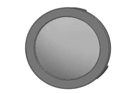
Fig.7 Three dimensional model of subassembly

Tab.2 Properties of different materials
4.1 Static stiffness analysis

Fig.8 Displacement of system with gravity load along optics axis
The gravity load is applied in three perpendicular directions of the model to check the static stiffness,the theaim is to find out whether lens surface deformation and position error are in the tolerance limits.Fig.8 and Fig.9 are the displacement and stress of the system with one gravity load in the direction of optics axis(axisZ).The results in the figures show that the maximum displacement is 1.4 ×10⁻⁵mm,the maximum stress is 0.12 MPa.Displacement and stress in other two directions also meet the requirements of tolerance.To evaluate the influence of radial support structure on the lens with the gravity load,it is necessary to calculate lens surface deformation by using the FE results.The surface deformation physically represents the deviation of the deformed optical surface from the undeformed optical surface at each point on the optical surface.Lens surface 1 is the convex surface,surface 2 is the plat surface.The rigid body displacement and tilt of the lens are shown in Tab.3.The maximum rigid body displacement is 0.013 μm,the maximum tilt is 0.013″,and both are less than the tolerable limit.The P-V and RMS of the lens surface deformation are shown in Tab.4,and the lens maximum surface shape error RMS is 2.29 nm,less than 12.6 nm.The radial support structure can satisfy the static rigidity requirements.

Fig.9 Stress of the system with gravity load along optics axis
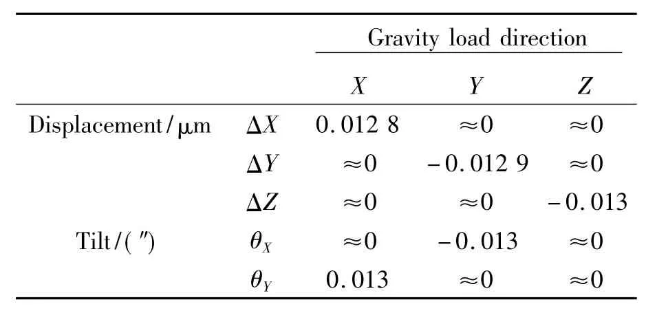
Table.3 Rigid body displacements and tilts of lens with gravity load
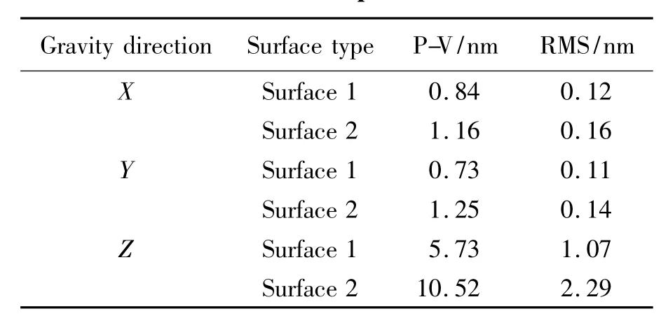
Tab.4 Surface shape errors of lens
4.2 Dynamic analysis
It is necessary to have a modal analysis to prevent lens subassembly from forced vibration during the launch.The first three order natural frequencies and vibration modes are shown in Tab.5.The first natural frequency is 1 301 Hz,higher than the specified value 300 Hz,therefore,the lens subassembly would not resonate under the influence of external environments.

Tab.5 The first three order natural frequencies and vibration modes
4.3 Thermal analysis
In the case of the space applications,the amplitude of temperature changes can be very large,Temperature change can modify the separation between optical elements and change the figure of the elements .It causes defocus and misalignment,so the support structure must make sure that the decenter as small as possible and minimize the stress and surface deformation of the lens.The detector's operation temperature is from 8 to 28℃and the fabrication and assembly temperature is 18℃,so it is necessary to analyze the subassembly under those extreme temperatures[12].The FE model is defined with restrictions of temperature of 8 and 28℃.Fig.10 and Fig.11 are the displacement and stress of the lens subassembly at 8 ℃.Fig.12 and Fig.13 are the displacement and stress of the lens subassembly at 28℃.When the subassembly is applied at 8℃,the maximum thermal stress would appear at the contact area of lens and support structure,because of the different CTEs of the material,as it is shown in Fig.11,and the maximum stress is 0.31 MPa,which is less than the tolerable limit.The contact between the structure and lens should be free of stress at the temperature of 28℃ as shown in Fig.13.To evaluate the influence of lens radial support on the lens with thermal load,lens surface deformation is calculated.Tab.6 is the rigid body displacement and tilt of lens with thermal load.The maximum rigid body displacement is 0.42 μm,and the maximum tilt is 0.076″,which are less than the tolerable limit.Tab.7 is lens surface deformation.It shows that the maximum surface shape error RMS is 11.69 nm,which is less than the tolerable value 12.6 nm.Radial support structure is compared with general support structure under the same thermal load.Fig.14 and Fig.15 are the displacement and stress of general support subas-sembly at 8℃,which shows that the stress and deformation are much larger than radial support,and the stress distribution is more uneven.Compared with general support structure,the radial support is more insensitive to temperature change and has a better ability to keep lens alignment.
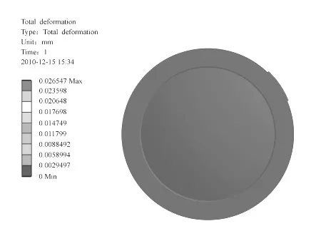
Fig.10 Displacement of radial support structure subassembly at 8℃
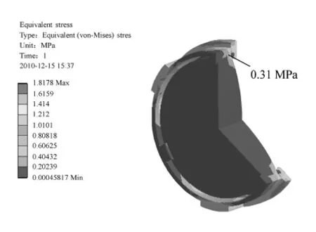
Fig.11 Stress of radial support structure subassembly at 8℃
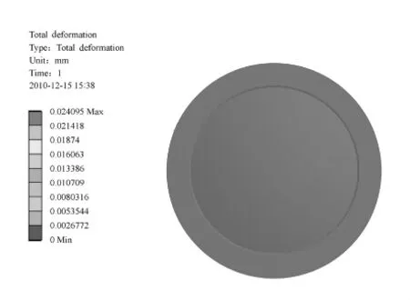
Fig.12 Displacement of radial support structure subassembly at 28℃

Fig.13 Stress of radial support structure subassembly at 28℃
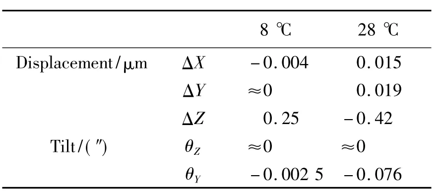
Tab.6 Rigid body displacements and tilts of lens with thermal load

Tab.7 Surface shape error of lens at different temperatures

Fig.14 Displacement of general support structure subassembly at 8℃
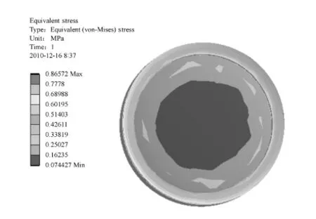
Fig.15 Stress of general support structure subassembly at 8℃
5 Conclusions
A lens radial support structure was designed on the characteristics and technical requirement of the optical system of a carbon dioxide detector for specifications.To verify the reasonability of the structure,the dynamic and static rigidities as well as thermal characteristics were analyzed.In order to improve the analysis accuracy,a nonlinear finite element was applied.The results show that the lens radial support structure can better keep the lens alignment and more insensitive to the temperature change,and also can effectively reduce the lens surface deformation caused by the gravity load and temperature change.The maximum surface-shape error RMS and the maximum tilt error are 11.69 nm and 0.076″,which are less than the specified value RMS 12.6 nm and 1″,respectively.The radial support structure design is rational,and fully meets the requirements of carbon dioxide detectors.
[1]DAVID C,CHARLES E M,PHILIP L.NASA Orbiting Carbon Observatory:measuring the column averaged carbon dioxide mole fraction from space[J].J.Appl.Remote Sensing,2008,023508:15-50.
[2]DAVID C.The need for atmospheric carbon dioxide measurements from space:contributions from a rapid reflight of the Orbiting Carbon observatory[R].Pasadena,California:Atmospheric Carbon Dioxide Measurements From Space,2009,321:1-23.
[3]CARL C L,RANDY P,BRETT H,et al..System for establishing best focus for the Orbiting Carbon Observatory instrument[J].Optical Eng.,2009,073605:1-3.
[4]HUANG E W.Gemini primary mirror cell design[J].SPIE,1996,2871:291-300.
[5]KAERCHAER H.The evolution of the SOFIA telescope system design-lessons learned during design and fabrication[J].SPIE,2003,4857:251-260.
[6]BITTER H,ERDMAN M,HABERLER,et al..SOFIA primary mirror assembly:structural properties and optical performance[J].SPIE,2003,4857:266-278.
[7]JOHN J B.Precision lens mounting:US,4733945[P].1988-04.
[8]AHMAD,HUSE R L.Mounting for high resolution projection lenses:US,4929054[P].1990-06.
[9]PAULR Y J.Opto-Mechanical Systems Design[M].Boca Raton,Florida:CRC Press Taylor& Francis Group,2006.
[10]SUEMATSU Y,TSUNETA S,ICHIMOTO K,et al..The solar optical telescope of solar-B:the optical telescope assembly[J].Solar Physics,2008,249:197-220.
[11]辛雪军,陈长征,张星祥,等.平行光管主反射镜组件的非线性有限元分析[J].中国光学与应用光学,2010,3(2):171-174.XIN X J,CHEN CH ZH,ZHANG X X,et al..Nonlinear analysis of primary mirror subassembly for collimator based on finite element method[J].Chinese J.Opt.Appl.Opt.,2010,3(2):171-174.(in Chinese)
[12]刘伟.小型Offner凸光栅光谱成像系统的结构设计及分析[J].中国光学与应用光学,2010,3(2):159-162.LIU W.Design and analysis of structure of compact offner spectral imaging system[J].Chinese J.Optics Appl.Opt.,2010,3(2):159-162.(in Chinese)
