EFFECT OF COLD SPRAY PARTICLE CONDITIONS AND OPTIMAL STANDOFF DISTANCE ON IMPACT VELOCITY
2011-09-27WANGXiaofangYINShuoXUBaopeng
WANG Xiao-fang, YIN Shuo, XU Bao-peng
(1.School of Energy and Power Engineering,Dalian University of Technology,Dalian 116024,China;2.Faculty of Engineering,Kingston University,London SW15 3DW,England)
0 Introduction
Cold spray,also called cold gas-dynamic spray (CGDS),is radically different from conventional thermal spray methods.The deposition process relies purely on kinetic energy rather than the combination of thermal and kinetic components.In this process,spray particles(generally<50μm)are accelerated to a high velocity(ranging from 300to 1 200m/s)by the supersonic gas flow which is generated in the convergent-divergent de Laval nozzle[1-4].A coating is formed through the intensive plastic deformation of particles impacting upon a substrate at a temperature well below the melting point of spray material[5,6].Generally,there exists a critical velocity for a given spray material,at which the transient from erosion of substrate to particle deposition takes place[2-6].Only if the particle impact velocity is above the critical value,could the coating be formed.Cold spray has many advantages,such as the wider choices of metals and alloys as coating materials,the capability of oxygen-free coating and high deposition efficiency[4,7-10].It has attracted more and more attentions now.
During the past decade,several researchers had focused on the effect of particle conditions on its acceleration behavior inside and outside the nozzle.Jen,etal.[11]reported that the bow shock waves almost had no effect on copper particles of more than 5 μm and significantly affected the particles less than 1μm through CFD simulations.Li,etal.[12]further showed that particles with smaller size,lower density or more irregular shape were easier to be accelerated by the carrier-gas via numerical method.Pattison,etal.[13]confirmed this using the experiment in a free jet.However,a systemic investigation on effect of particle size,density and shape on its impact velocity,which is the most important factor in cold spray process,is still lacking.
For the optimal standoff distance,there have been very little literatures concerning this research.Gilmore,etal.[4]sprayed copper particles with helium and found that particle velocity only began to decrease when the standoff distance was more than 50mm.Stoltenhoff,etal.[14]gave aproof to this observation by using numerical simulation.Pattison,etal.[13]employed the experimental method to point out that there exists an optimal region in which the deposition efficiency can reach a high value.Although some reports referred to the standoff distance in cold spray,the reason why the optimal standoff distance exists and how to determine it are still not well understood.
Therefore,in this study,the numerical method was employed to give a detailed investigation into the effect of particle conditions on its impact velocity, and examine the determination of optimal standoff distance.
1 Mathematical modeling
1.1 Numerical modeling
Numerical modeling is performed by using the CFD software Fluent to determine the flow field of free jet and impact jet outside the nozzle.The gas is taken as an ideal and compressible one.A coupled implicit method is used to solve the flow field and the result of flow field in a steady state is obtained.The standardK εturbulence model available in Fluent is utilized for modeling the turbulent flow in the simulation.The accelerating of particles is computed using discrete phase modeling (DPM).The interaction of particle with gas is not considered in this study.The governing equations for gas flow include the physical laws of conservation of mass,momentum,and energy.Models describing the dynamic behavior of in-flight particles during the two-phase flow have been well documented in the Fluent manual[15].
1.2 Geometrical model and boundary conditions
Owing to the axisymmetrical characteristics of the flow field in this study,a two-dimensional symmetrical model is employed as shown in Fig.1.The diameter of the nozzle exit is chosen as 4mm.Pressure-based boundary conditions are applied to the inlet and outlet,while no-slip condition and a fixed heat flux of zero are enforced at the nozzle wall and substrate.The atmosphere is treated as non-reflectingboundary.The meshing is conducted with the quad elements.The initial velocity of the carriergas has been set as 617m/s at the nozzle exit according to the authors′previous experimental results.Moreover,it is assumed that the initial velocity of particles is defined as the same value as that of the carrier-gas in order to ensure that all the particles have a same initial condition at the nozzle exit and make the comparison much clearer.
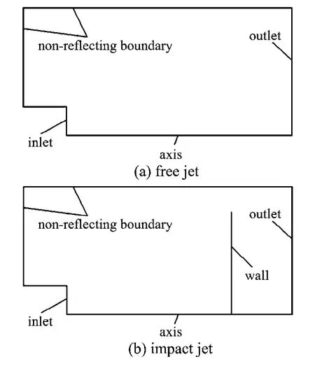
Fig.1 Schematic diagram of the computational domain and boundaries of the free jet and the impact jet
2 Results and discussion
2.1 Gas flow field in the free jet
Fig.2illustrates the pressure profile in the free jet by using air as carrier-gas in order to find the general flow feature of free jet flow field.A well-formed complex wave structure can obviously be seen,where dilatational waves and oblique shock waves appear alternately.The first region near the nozzle exit presents several dilatational waves owing to the non-ideally expanding with a rapid acceleration of gas velocity and then presents compression waves as a result of the reflection at the atmosphere boundary.These compressional waves are combined to the oblique shock wave to reduce the flow velocity with increasing the pressure and the temperature sharply.The periodic variation of the wave structure results in the fluctuation of carrier-gas velocity at the centerline.Furthermore,it is also noticed that the oscillation amplitude of this complicated wave structure is reduced gradually along the jet direction because of the viscous dissipation.Eventually,the flow energy is dissipated and stabilized to the environmental pressure through continuous adjustment of the supersonic flow.

Fig.2 Pressure profile outside the nozzle in the free jet using air as carrier-gas at a pressure of 0.252MPa and a temperature of 300K

Fig.3 Velocity plot of carrier-gas along the nozzle centerline
Fig.3shows the velocity plot of carrier-gas along the nozzle centerline.It is clear that the gas velocity experiences a periodic fluctuation along the centerline in the form of a rapid increase followed by a steep decrease.The carrier-gas has been accelerated through the dilatational wave,and then starts to decrease when penetrating into the oblique shock wave until the next expansion wave comes.Moreover,the maximum gas velocity is about 840m/s at the location of 12mm from the nozzle exit after the first dilatational wave and the subsequent peak values decrease gradually.The velocity distribution can be well explained by the wave structure shown in Fig.2.Jodoin,etal.[16]also reported the same phenomenon through experiments using nitrogen as carrier-gas at the stagnation pressure of 2.4MPa and temperature of 733K.
2.2 Effect of particle size,density and shape on particle impact velocity
Following the free jet study,impact jet is simulated to clarify the effect of particle size,density and shape on particle impact velocity.Fig.4exhibits the pressure profile in the impact jet with the substrate 16mm away from the nozzle exit by using air as carrier-gas.It is obvious that the existence of the substrate causes the wave structure more different from that in the free jet.The obvious dilatationalwaves are seen outside the nozzle exit,followed by the oblique shock waves.Between the nozzle exit and the substrate,there exists a wellformed bow shock wave located close to the substrate,which arises from the interaction between the gas flow and the substrate.The pressure in this region is well confined,leading to a much higher pressure increase at the substrate and a significantly different flow pattern.The flow velocity decreases rapidly to nearly zero when the gas flow penetrates into the bow shock wave and approaches the substrate.
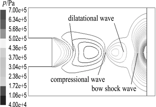
Fig.4 Pressure profile outside the nozzle using air as carrier-gas with the substrate 16mm away from the nozzle exit at a pressure of 0.252MPa and a temperature of 300K
Fig.5compares the impact velocities of spherical copper, titanium and aluminum particles in order to find the effect of material density on particle impact velocity.The densities of aluminum,titanium and copper powders are 2 719,4 850and 8 978kg/m3,respectively.It is apparent that three types of particles almost have the same velocity changing tendency.Aluminum particle with the lowest density is more susceptible to carrier-gas than the other two particles.Therefore,it is easily picked up and accelerated to the highest velocity before entering into the bow shock wave.However,when penetrating into the bow shock waves,aluminum particle is also easily decelerated and the velocity drops steeply from the highest value of nearly 640m/s to the lowest value of about 610m/s,while titanium particle and copper particle achieve relatively higher impact velocities due to their large densities.Moreover,in order to examine the influence of particle shape on the particle impact velocity,the comparison of spherical and non-spherical titanium particles with the equivalent diameter of 5μm is also given in Fig.5.It is easily found that the non-spherical titanium particle has a higher velocity before penetrating into the bow shock waves,but a lower impact velocity.This fact can be linked to the morphologies of particles.The drag coefficient of a sphere particle is less than that of an equivalent diameter but irregular shape particle.Therefore,the non-spherical titanium particle can be easily picked up by the gas flow and also seriously affected by the bow shock waves.
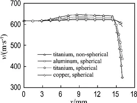
Fig.5 Comparison of velocities of spherical copper,titanium, aluminum particles and nonspherical titanium at the standoff distance of 16mm along the nozzle centerline
Fig.6shows the centerline velocity of copper particles with different diameters in the impact jet.Small particle is easily picked up through the drag force of carrier-gas compared with large one.However,as the particles traverse the bow shock waves,the acceleration suddenly becomes deceleration.When coming to the bow shock waves,large particles are affected slightly by the drag force and maintain sufficient impact velocity as a result of the significant momentum and energy.On the contrary,small and light particles are decelerated steeply by thebow shock waves although they can be accelerated greatly by the carrier-gas before entering the bow shock waves.The final impact velocities of copper particles with different diameters are displayed in Fig.6.It gives a clear suggestion that the larger particle can achieve a higher impact velocity when impacting the substrate.It is clearly found that with increasing the particle size,the effect of gas flow becomes slight and the impact velocity rises gradually.Jen,etal.[11]also reported that the bow shock waves almost had no effect on copper particle with a diameter larger than 5 μm and significantly affected the particle with a diameter less than 1μm.

Fig.6 Comparison of velocity of copper particles with different diameters at the standoff distance of 16mm along the nozzle centerline
2.3 Optimal standoff distance
Fig.7shows the effect of standoff distance(d)on impact velocity by using copper particles with different sizes.It is clearly observed that there exists an optimal standoff distance between the nozzle exit and the substrate.Under the given condition in this study,the optimal distance is 16mm.The reason for this is that the carrier-gas velocity at 16mm is the lowest in the first changing period in the free jet as shown in Fig.3.Therefore,when setting the substrate at this position,the intensity of the bow shock waves must be very small,which could weaken the deceleration effect of the bow shock waves on particle impact velocity and thus particle can achieve a higher impact velocity.However,it also can be noticed that in the free jet there exist several velocity changing periods and each has a minimum point of gas velocity.Thus,it can be deduced that there must be another limitation to determine the optimal standoff distance of 16 mm.In order to find this determinant,the standoff distance of 32mm is chosen.The carrier-gas velocity at this distance is the lowest in the second changing period in the free jet.Fig.8shows pressure profile outside the nozzle using air as carrier-gas with the substrate 32mm away from the nozzle exit at a pressure of 0.252 MPa and a temperature of 300K.It can be seen that the particle experiences twice acceleration and three times deceleration before entering into the bow shock waves due to the alternantdilatational waves and oblique shock waves.After the second dilatational wave, the deceleration effect of drag force becomes more intensive than the positive drag force as a result of the energy dissipation in carrier-gas.Therefore,the in-flight particle velocity can not reach the peak before permeating into the bow shock waves.However, when the standoff distance is 16mm as shown in Fig.5,the particle experiences twice acceleration and only once deceleration.The particle uses the positive drag force effectively to obtain a higher velocity compared with that the standoff distance is 32 mm.
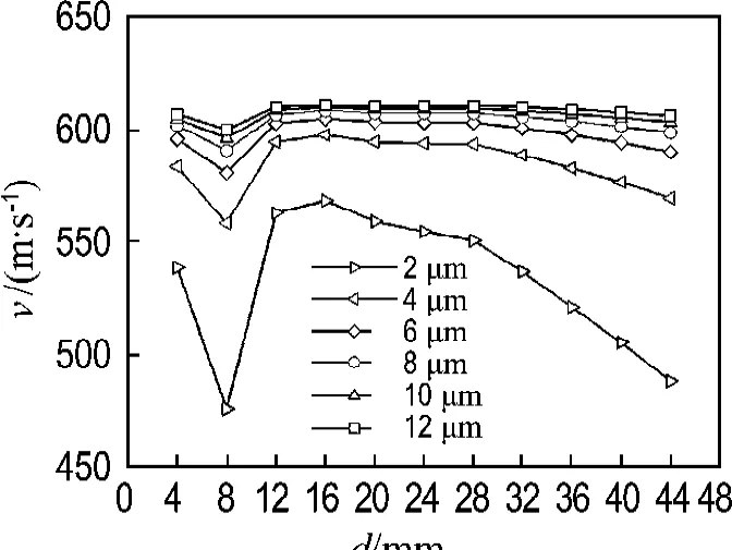
Fig.7 Effect of standoff distance on impact velocity by using copper particles with different diameters

Fig.8 Pressure profile outside the nozzle using air as carrier-gas with the substrate 32mm away from the nozzle exit at a pressure of 0.252MPa and a temperature of 300K
From the discussion above,it can be easily concluded that the determination of the optimal standoff distance needs two essential conditions to ensure that the particle can achieve the highest impact velocity.The first one is that the substrate must be located at the place where the carrier-gas velocity is lower in the free jet.The other is that the particles should be accelerated twice before entering the bow shock wave,which means there must be two dilatational waves in front of the bow shock wave.The previous experimental study on the standoff distance conducted by Pattison,etal.[13]also reported the similar results that the optimal standoff distance in cold spray linked closely to the bow shock wave intensity.Only for the proper standoff distance at which the bow shock wave intensity is weak,the particle impact velocity and the deposition efficiency can reach a higher value.Also,Li,etal.[17]reported the same phenomenon that standoff distance actually affected the impact velocity and the optimal standoff distance indeed existed in cold spray by experiment method.These facts further enhance the value of this study.
3 Conclusions
(1)Particle size,density and shape play critical roles in in-flight particle velocity and impact velocity.Particles with small size,low density or irregular shape can be easily affected by the carrier-gas.These particles can be accelerated to a higher velocity by the positive drag force and decelerated sharply by viscous dissipation and the bow shock wave.But large size,high density or spherical particle is not sensitive to the carrier-gas and thus can obtain a higher impact velocity while impacting the substrate.
(2)The existence of the substrate causes the wave structure more different from that in the free jet.The obvious bow shock wave which arises from the interaction between the gas flow and the substrate,leading to a steep deceleration of particle velocity.
(3) There exists an optimal standoff distance.The determination of this distance requires two conditions.The first one is that the substrate must be located at the place where the carrier-gas velocity is lower.The other is that particles should be accelerated twice before entering the bow shock wave,which means there must be two dilatational waves in front of the bow shock wave.
[1]ALKIMOV A P,KOSAREV V F,PAPYRIN A N.A method of cold gas-dynamic deposition [J].Doklady Akademii Nauk SSSR,1990,318 (5):1062-1065
[2]DYKHUIZEN R C,SMITH M F.Gas dynamic principles of cold spray[J].Journal of Thermal Spray Technology,1998,7(2):205-212
[3]ASSADI H,GARTNER F,STOLTENHOFF T,etal.Bonding mechanism in cold gas spraying [J].Acta Materialia,2003,51(15):4379-4394
[4]GILMORE D L,DYKHUIZEN R C,NEISER R A,etal.Particle velocity and deposition efficiency in the cold spray process [J].Journal of Thermal Spray Technology,1999,8(4):576-582
[5]PAPYRIN A.Cold spray technology [J].Advanced Materials and Processes,2001,159(9):49-51
[6]KARTHIKEYAN J.Cold spray technology [J].Advanced Materials and Processes,2005,163(3):33-35
[7]STEENKISTE T V, SMITH J, TEETS R.Aluminum coatings via kinetic spray with relatively large powder particles [J].Surface and Coatings Technology,2002,154(2-3):237-252
[8]LI C J,LI W Y.Deposition characteristics of titanium coating in cold spraying [J].Surface and Coatings Technology,2003,167(2-3):278-283
[9]KIM H J,LEE C H,HWANG S Y.Fabrication of WC-Co coatings by cold spray deposition[J].Surface and Coatings Technology,2005,191(2-3):335-340
[10]LI W Y,LI C J,WANG Y Y,etal.Effect of Cu particle parameters on its impacting behavior in cold spraying [J].Acta Metallurgica Sinica,2005,41(3):282-286 (in Chinese)
[11]JEN T C,LI L J,CUI W Z,etal.Numerical investigations on cold gas dynamic spray process with nano-and microsize particles[J].International Journal of Heat and Mass Transfer,2005,48(21-22):4384-4396
[12]LI W Y,LI C J.Optimization of spray conditions in cold spraying based on the numerical analysis of particle velocity [J].Transactions of Nonferrous Metals Society of China,2004,14(s2):43-48
[13]PATTISON J,CELOTTO S,DHAN A,etal.Standoff distance and bow shock phenomena in the cold spray process [J].Surface and Coatings Technology,2008,202(8):1443-1454
[14]STOLTENHOFF T,KREYE H,RICHTER H J.An analysis of the cold spray process and its coatings[J].Journal of Thermal Spray Technology,2002,11(4):542-550
[15]Fluent Inc..FLUENT 6.1User′s Guider [Z].Lebanon:Fluent Inc.,2003
[16]JODOIN B,RALETZ F,VARDELLE M.Cold spray modeling and validation using an optical diagnostic method [J].Surface and Coatings Technology,2006,200(14-15):4424-4432
[17]LI W Y,ZHANG C,GUO X P,etal.Effect of standoff distance on coating deposition characteristics in cold spraying [J].Materials and Design,2008,29(2):297-304
