Research on Estimation of Time Delay Difference in Passive Locating for Impulse Signal
2011-07-25XUFu徐复HEWenxiang何文翔HUIJunying惠俊英YUYun余赟
XU Fu(徐复),HE Wen-xiang(何文翔),HUI Jun-ying(惠俊英),YU Yun(余赟)
(1.726th Research Institute,China Shipbuilding Industry Corporation,Shanghai 201108,China;2.National Laboratory of Underwater Acoustic Technology,Harbin Engineering University,Harbin 150001,Heilongjiang,China)
Introduction
Active sonars are commonly used to detect targets in underwater acoustic countermeasure.Usually,they emit much stronger surveillance impulses than environmental noise.Therefore,an underwater working platform can have the upper hand in a countermeasure if it could use the surveillance impulses to locate the sonar.Since the parameters of surveillance impulse signal and emitting time are all unknown,such a passive locating has to rely on the technique of three-point positioning,in which the time delay difference estimation of adjacent sensors is a key issue.For broadband signals,it has been solved after long term studies by using cross correlation estimation technique[1],and the estimation precision relates to the band width of the received signals.When it is used for impulse targets,its estimation precision will not be guaranteed because the band width and other parameters of impulse signals are decided by the emitting side rather than receiving side in real underwater acoustic countermeasure.Besides,in the environment of multiple sea channels,the signals received by a sensor include direct arrival and reflected arrivals,and it leads to multiple correlation peaks;moreover,because of the waveform distortion,the desired correlation peak will deviate from its expected position.These phenomena make the cross correlation time delay difference estimation technique hard to meet the precision requirements in passive locating.Therefore,the passive locating for impulse signal has to rely on threshold technique[2-4]called as direct estimation in this paper.Though it has been studied for many years,it still suffers from instability and poor precision[4],thus,further researches on these pro-blems are necessary.
Starting from the principle of three-point positioning,analyzing the relativity between time delay and time delay difference estimation errors,in this paper,the improvement of the direct estimation stability by introducing channel equalization technique.The estima-tion error of time delay difference can be considered as a random quantity.Analyzed the different contribution modes of the phase lag and number of periods of impulse signals to the time delay estimation error,the possibility to simplify the compensation for estimation errors by utilizing the diversities of their contribution modes is studied,thus,some feasible compensation methods to improve the estimation stability and precision are obtained.Applying these results comprehensively,and setting more thresholds to get more estimation samples,a cooperative multi-threshold estimation for time delay difference is finally proposed,which could improve both precision and stability efficiently.
An ideal acoustic array is used in this paper to discuss the stability and precision of time delay difference estimation in passive locating.
1 Amendment Estimation
1.1 Stability of Time Delay Difference Estimation of Impulse Signals in Three-point Positioning
In the three-point positioning,as shown in Fig.1,the signal propagates spherically from sound sourceS,and arrives at the three sensorsA1,A2andA3in a linear array with equal space.Assume that the sensors’spaces areA1A2=A2A3=d,the distances between the source and individual sensors areSA1=r1,SA2=r2andSA3=r3,respectively.
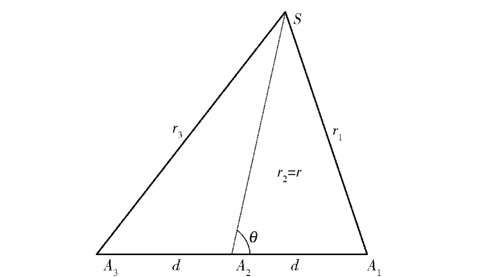
Fig.1 Model of three point positioning
Letθbe azimuth,r=r2be range.From geometric relation,the estimation formulas of direction and range are[3]
wherecdenotes the sound velocity.The variance of range estimation is[5]

wherele=dsinθand equals to a half of the array’s equivalent aperture[6].
It can be seen clearly from above formulas that the stabilities of azimuth and range estimation depend on the time delay difference between received signals only,and have no direct relations with the time delay itself,becausedandcare all constant.This fact reveals the way to get stable estimation of time delay difference under the condition of instable estimation of time delay,and can be illustrated further as follows.
Suppose the time delay estimation of arrivals at the sensorsA1andA2are(τ1+Δτ1)and(τ2+Δτ2),respectively,whereτ1andτ2are the real time delay of the arrivals,Δτ1and Δτ2are the estimation errors.According to the definition of time delay difference,τ12can be expressed as

Obviously,if there exist the estimation errors,τ12will remain unchanged when Δτ1equals to Δτ2.The estimation error of time delay difference is proportional to the difference of estimation error of time delay only,rather than the estimation errors of time delay themselves,so that the estimation stability of time delay does not equate to the estimation stability of time delay difference.In the case of instable estimation of time delay,the estimation of time delay difference can still be relatively stable,if the estimation errors of time delay could be closer to each other by using a suitable method.
For an impulse sound sourceS,the waveforms of received signals can be analyzed.Fig.2 shows the rising edges of impulse signals received byA1andA2from the same impulse sound source.Because of the affection of sea channels,the rising edges are distorted.
Fig.2 Envelops of two received signals
In Fig.2,from left to right,the first one is the received pulse ofA2,and the second is that ofA1.Let dash line denote the threshold,dot dash lines indicate the exact moments when impulses arrive.It can be seen clearly that the estimation errors Δτ1and Δτ2will be brought out,if the time delay estimation is performed by means of threshold,because of the waveform distortion.Since the signals travel via different paths,their distortions are also different,thus,Δτ1and Δτ2are not equal,leading to the estimation error ofτ12.In the environment of multiple sea channels,the waveform distortions are brought out in a random way,therefore,the direct estimation is neither stable nor precise and hard to meet the technical requirements of passive locating.
To obtain a stable estimation of time delay difference under the condition of instable estimation of time delay,Δτ1should have the same value as Δτ2.Since Δτ1and Δτ2are induced by the waveform distortion,and waveform distortion is induced by impulse responses of the acoustic channels,therefore,to make Δτ1and Δτ2equal means to make the channels have the same impulse response.In real sea environment,inconsistency is an inherent characteristic in multiple channels and can not be changed[7].However,the impulse responses of one of the two acoustic channels can be reformed by using channel equalization to make its equivalent impulse response identical to that of the other channel.
1.2 Principles of Amendment Filtering
The channel equalization can be realized with the help of amendment filter,as shown in Fig.3.
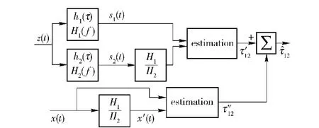
Fig.3 Sketch of amendment filter
An impulse signalz(t)arrives to two sensors via two different channels with impulse responsesh1(t)andh2(t).For poor correlative signalss1(t)ands2(t),their correlativity can be improved if channel 2 is amended by amendment filter.Suppose that the frequency response of the amendment filter is
whereH1andH2are frequency responses of channels 1 and 2,respectively.s2(t)passing through the amendment filter is equivalent tos2(t)processed by time reversal of channel 2 firstly and passing through channel 1 then.As a result,the equivalent impulse response of channel 2 will be the same as impulse response of channel 1.Ideally,the rising edge distortion of impulsess2(t)ands1(t)will be the same.
From Eq.(5),it can be seen that the key to implementation of amendment filtering is to obtain impulse responses of the two channels.However,in practice,there is no possibility or necessity to get the exact channel parameters through measurements.According to the theory of underwater acoustical signal processing,the impulse signal received by a sensor is the output of a channel through which the impulse signal has traveled so that the channel information has already been attached to the received signal,since the output of a channel is the convolution of its impulse response with input signal to the channel.LetZdenote the frequency response ofz(t),S1andS2denote the frequency responses ofs1(t)ands2(t),respectively,thenS1andS2can be written as

Therefore,the frequency response of amendment filter can be solved.

And,its impulse responseh12(t)can be recov-ered by inverse Fourier transform ofH12.

In real sea,the received signalss1(t)ands2(t)will have background noise,because the sensors are always surrounded by environment interferences.For easy engineering realization,the noise affection can be neglected in derivation of(8),since the passive locating for impulse signals is usually conducted under the condition of high SNR(signal to noise ratio).Strictly speaking,(8)is an approximation formula ofH12,therefore,the output signals of two channels will not be completely identical.Whens2(t)passes through the amendment filter,it will be delayed for a certain quantity called additional time delay,which must be compensated afterwards.The 3rdchannel shown in Fig.3 is used to measure the additional time delay introduced by amendment filter,where the test signalx'(t)is synthesized after the parameter estimation of impulse signals.
The received impulse signals shown in Fig.2 can be processed by using the amendment filter,as shown in Fig.4.
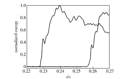
Fig.4 Waveforms of received signals in two channels after amendment
Compared Fig.4 with Fig.2,the rising edge of signal received byA2is changed significantly after amendment filtering.Two impulses’correlation coefficient increases from 0.62 to 0.71;and the waveform similarity between two rising edges is improved as well.Therefore,the stability of time delay difference estimation can be improved if the channel equalization is performed before direct estimation.This processing technique can be named as amendment estimation.
1.3 Stability of Amendment Estimation
The stability of amendment estimation has to be verified by simulation.The simulation conditions are stated as follows.
根据以上所测数据,计算出不同转速下的土壤体积含水率,取平均值作为最终的土壤体积含水率,从而得到实测的土壤水分特征曲线。
Two receiving sensors and an impulse sound source are located in a straight line.The sensor spacing is taken as 100 m.In the range of 9.1 to 10 km away from the outer sensor,10 measurement points with equal spacing of 100 m are set up.The time delays of impulse signals received by two sensors from each point are measured,respectively.Therefore,it is a fixed point simulation.According to the design scheme,the difference of time delay measured at each point will be the same.The environment of multiple sea channels can be formed by underwater acoustic channel simulation software.The sound velocity profile and some environmental parameters,such as sea depth,etc.,are quoted from a previous sea trial.Two kinds of impulse signals are used in the simulation.One of them is CW impulse of 8 kHz and another is LFM impulse with frequency band of 6-10 kHz.The pulse widths of two signals are all 20 ms,SNR is 20 dB and the sampling rate is 100 kHz.The time delay differences are measured by direct and amendment estimation respectively.The results are listed in Tab.1.
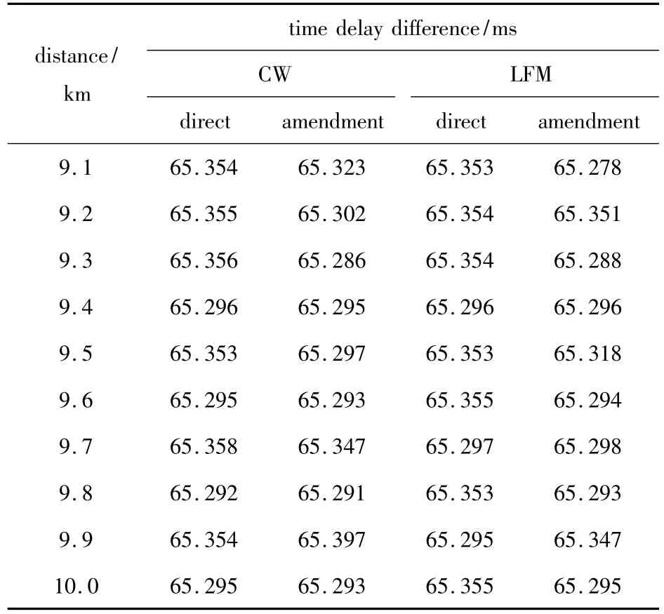
Tab.1 Results of time delay difference estimation in direct and amendment estimations
Rejected a pair of extremes in each column of Tab.1,the results of stochastic analysis for each data column are shown in Tab.2.
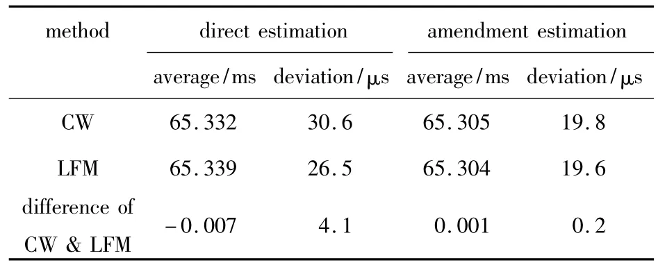
Tab.2 Stochastic analysis results for direct and amendment estimations
Tab.2 shows that the standard deviation of amendment estimation is less than that of direct estimation,and the variations of average and deviation of amendment estimation are also less than those of direct estimation,thus,the amendment estimation is more stable and precise than the direct estimation.
2 Integer Period Error Compensation
2.1 Time Delay Difference Estimation in Low SNR
Stochastic average is a commonly used method to reduce measuring error.It requires enough number of samples.Since the threshold can obtain only one estimation for an impulse signal only,therefore,to get more estimation samples,more thresholds are necessary.However,the selection of threshold level is related to SNR.The smaller the threshold level is,the lower the SNR will be;and the lower the SNR is,the poorer the estimation precision will be.Thus,it is necessary to analyze the estimation precision of time delay difference in low SNR.The block diagram of simulation is shown in Fig.5.
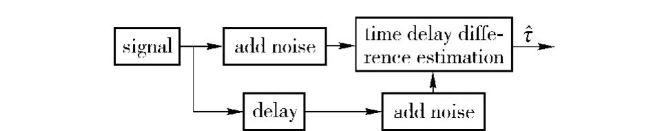
Fig.5 Block diagram of simulation
The frequency of CW impulse is 9.6 kHz,the sampling rate 48 kHz and the pulse width 200 ms.Three SNRs are taken,no noise and multiple path interference,15 dB and 10 dB,respectively.The simulation results are shown in Tab.3,whereτdenotes the time delay difference,^τthe estimation ofτ.
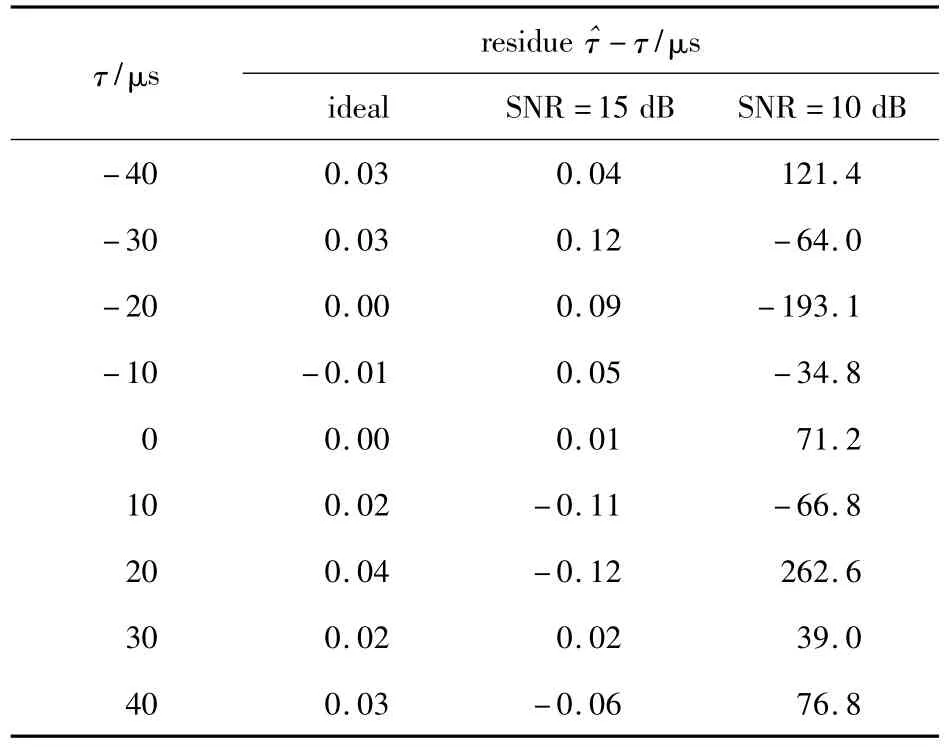
Tab.3 Estimation results of time delay difference in different SNRs
Tab.3 shows that all residual errors of time delay difference are less than 0.15 μs,if SNR is not less than 15 dB.However,when SNR declines down to 10 dB,the noise interference becomes much stronger,which makesresidualerrorincrease significantly.Therefore,it is necessary to develop a feasible method to compensate the estimation error in low SNR.
2.2 Integer Period Error Compensation
It is difficult to decide how many should be compensated for each sample in order to reduce estimation error,because its true value is unknown in practice.To solve this problem,some decision criteria and feasible methods should be established.
According to the theory of errors,the total observation error mainly depends upon those objects whose observation errors are greater than the others,when there are more than one observation objects.Considering the estimation error of time delay difference as a random quantity,the feasible processing method for error compensation may be developed by analyzing the contribution modes and shares of related observation objects.
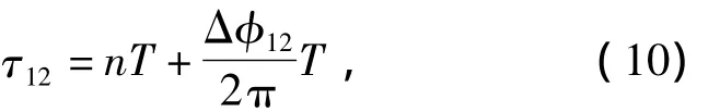
whereTis the signal period,nthe number of periods and Δφ12the phase lag of two signals.SinceTis a constant,onlynand Δφ12are contributors to estimation error ofτ12.If Δφ12is selected to be the main contributor,it will be puzzling to determine the compensation quantity,because Δφ12is continuous in the number axis such that the compensation can be selected as any value without limitation.Whereas,ifnis selected,because it is discrete in the number axis,the compensation quantity selected must be integer,which is easy to determine,and can be used as a decision criteria.Therefore,nshould be selected as the main contributor for error compensation.For this purpose,the contribution share ofnto the total observation error should be much larger than Δφ12,i.e.to make the estimation precision of Δφ12much higher thann,then the estimation error ofτ12can be considered as the estimation error ofnmainly.In other words,the estimation error ofτ12is approximately integer times ofT,thus,Tcan be taken as the compensation step to compensate the estimation error ofτ12.This method is called as integer period error compensation in this paper.
The integer period error compensation can only be conducted on the premise of high precision estimation for phase lag.For this reason,the integer period error compensation method can be used for low SNR signals only after the precision of phase lag estimation is improved.
2.3 Time Delay Difference Estimation of ALE Filtering
It is well known from signal processing theory and practice that the adaptive line enhancement filtering(ALE)can enhance the energy of line spectrum of impulse signal and improve the SNR of sinusoidal signal and precision of phase estimation.Therefore,an ALE filter can be inserted into the processing flowchart of Fig.5,in which the phase lag is measured by a Notch filter.The reformed block diagram of simulation is shown in Fig.6.
In Fig.6,the estimation of time delay difference is divided into two steps.Firstly,the raw value of time delay difference is obtained by using the threshold;then,the precise phase lag is measured by a Notch filter.The final results are obtained after the integer period errors are compensated.
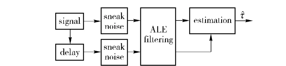
Fig.6 Simulation block diagram adding ALE filtering
In order to verify the validity of ALE filtering,the simulations are conducted in SNR of 10 dB and the other simulation conditions are the same as that in section 2.1.The simulation results are shown in Tab.4.
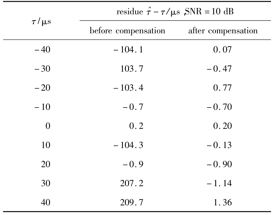
Tab.4 Time delay difference estimations before and after compensation
The second column in Tab.4 shows the residue before compensation.Even though residue is still hundred microseconds before compensation,it becomes much smaller after compensation,as shown in the third column.All the residues are very close to that obtained under the condition of higher SNR.
There should be a reference value for performing the integer period error compensation.If the input SNR is fixed,the estimation sample of time delay difference obtained in higher threshold is relatively more reliable than that in lower threshold,thus,the former can be chosen as the reference for the integer period error compensation latter.The detailed explanation is given as follows.
Calculating the algebraic sum ofnTand the estimation of time delay difference in low threshold and in-creasing or decreasingnsuccessively,if the difference of the sum and the reference estimation of time delay difference reaches to minimum,the desired compensation quantitynTwill be obtained.In practice,signal periodTcan be obtained from the parameter estimation of impulse signals before compensation.It is noticed that this method requires relatively higher input SNR to ensure the higher output SNR after input impulse signals passes the lowest threshold.
3 Cooperative Multi-threshold Estimation
3.1 Cooperative Multi-threshold Estimation of Time Delay Deference
The methods developed in section 2 provide a foundation to increase the number of estimation samples by setting more thresholds.The number of thresholds shall be decided after analyzing the relation between it and ranging precision,because the computation loads of the system will be enlarged greatly with the number of thresholds.Three thresholds with high,medium and low levels are set in this paper through detailed analyses and simulations.Since there is no channel equalization error in the samples of direct estimation,it is complementary with the amendment estimation.Besides,it can be seen from Tab.1 that a part of samples in the direct estimation is very close to that in the amendment estimation.Viewing either from complementarity or increase of samples,the direct estimation samples shall be accepted with no doubt.Based on the analyses above,the direct estimation can be combined with the amendment estimation to process the received signal cooperatively with three thresholds,as shown in Fig.7.
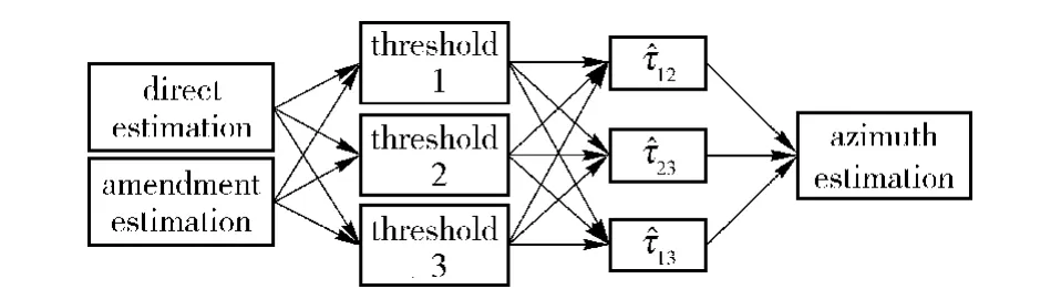
Fig.7 Cooperative multi-threshold estimation
When the received signals are processed following the flowchart in Fig.7,for each group of received impulse signals,6 groups of estimation samples of time delay difference can be obtained,thus,the number of samples is 6 times of the original.This processing technique is named as cooperative multi-threshold estimation in this paper,and its efficiency will be verified via sea trial data in the next section.
3.2 Results of Sea Trial Data Tests of Passive Locating
The sea trial was carried out in a certain sea area of our country.A light boat was selected as the target cruising on the sea and a mother ship was used to receive continuously impulse signals emitted by the target.In the trial,the target’s cruising track was recorded by radar,which was used later as a reference in comparison.
The time delay difference in the sea trial data tests of passive locating is estimated by the cooperative multi-threshold method. Then, these data can be sieved and smoothed in post processing.The azimuth detection results are shown in Fig.8,where the vertical axis represents time in second,and the horizontal axis represents azimuth in degree.
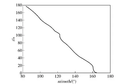
Fig.8 Azimuth results of sea trial
Fig.9 shows the ranging results,where the vertical axis is slope distance in meter,and the horizontal axis is series number of impulse signals.
Fig.10 is the results of comprehensive processing of sea trial data,where the vertical axis denotes the slope distance in meter and the horizontal axis the azimuth in degree.The solid line in the figure shows the passive locating result for the target,and the dash line the target track recorded by the radar.
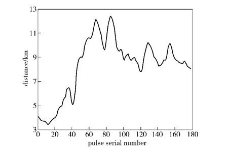
Fig.9 Ranging results of sea trial
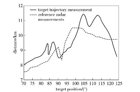
Fig.10 Comprehensive processing results of sea trial data
It can be seen that the target’s track obtained by the passive locating is close to that recorded by radar.Taking the radar’s data as a reference,the relative range errors of the passive locating are all less than 12%,as shown in Tab.5.
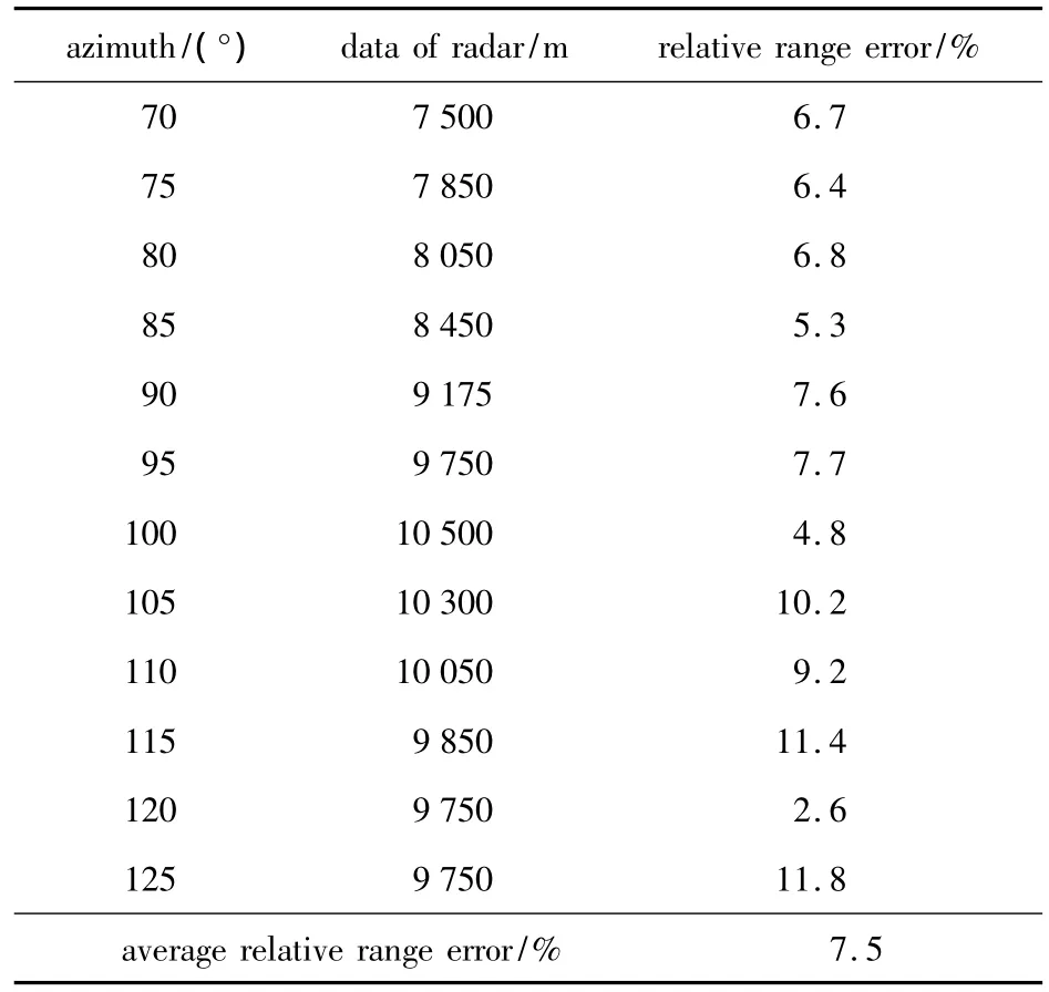
Tab.5 Relative range error in passive locating
4 Conclusions
The principle of three-point positioning indicates that the estimation stability for a target depends on the time delay difference of impulse signals received by the sensors.Based on the fact that the estimation error of time delay difference is proportional to the difference of estimation errors of time delay only,even though the time delay estimation is instable,the stability of time delay difference estimation can still be improved only if the waveform similarity of received impulse signals can be improved better enough by means of channel equalization.
According to the theory of errors,observation error is induced mainly by those observation objects which have poorer estimation precision.Considering the estimation error of time delay difference as a random,the estimation of signal period number can be regarded as the main contributor to the estimation error of time delay difference after the precision of phase lag estimation is improved by applying ALE and Notch filtering.It leads to the development of the integer period error compensation method that can compensate the estimation error of time delay difference by using signal period as the compensation step.The simulation shows its effect.
The direct and amendment estimations are complementary.To utilize such complementarity and increase the number of estimation samples,the direct estimation can be combined with the amendment estimation to process impulse signals cooperatively with three thresholds.As a result,the cooperative multi-threshold estimation method is finally established in this paper.Its validity is verified in sea trial data tests of passive locating.The experiment results show the method's feasibility.
In real environment,the passive locating of impulse signals will be affected by a variety of factors.Therefore,further studies are necessary in future research.
[1]LI Qi-hu.Principles of digital sonar design[M].Hefei:Publishing House of Anhui education,2003.(in Chinese)
[2]Urik R J.Principles of underwater sound[M].Harbin:Publishing House of Harbin Engineering Institute,1990.(in Chinese)
[3]SONG Xin-jian,HUI Jun-ying,YIN Dong-mei.Research on underwater noise target passive ranging technology[J].Applied Acoustics,2005,24(3):133 - 139.(in Chinese)
[4]LI Yan-mei.Research on sonar pulse detection and passive ranging[D].Harbin:Publishing House of Harbin Engineering University,2003.(in Chinese)
[5]LI Qi-hu.Introduction to sonar signal processing[M].Beijing:Publishing House of Oceanography,1985.(in Chinese)
[6]Carter C G,Robinson R E.Ocean effects on time delay estimation requiring adaption.IEEE[J].Oceanic Engr,1993,18:367-378.
[7]HUI Jun-ying,SHENG Xue-li.Channels of underwater sound[M].Beijing:National Defense Industry Press,2007.(in Chinese)
猜你喜欢
杂志排行

Defence Technology的其它文章
- Application of Adaptive Backstepping Sliding Mode Control in Alternative Current Servo System of Rocket Launcher
- Optimization Design of Double-parameter Shift Schedule of Tracked Vehicle with Hydrodynamic-mechanical Transmission
- A New Single DIFAR Sonobuoy Target Location Algorithm
- Waveguide Invariant and Passive Ranging Using Double Element
- Reliability Sensitivity Analysis for Location Scale Family
- New Wideband Beam-forming Method Used in Underwater Communication System