The High Value CVT Concept——Cost Effective and Powerful
2011-07-06EnglischTeuberttzllerSimonWalterBaumgartner
A.Englisch,A.Teubert,A.Götz,E.Müller,E.Simon,B.Walter,A.Baumgartner
(LuK GmbH Co.KG,Germany)
1 Introduction
The number of continuously variable transmissions produced worldwide is increasing,espe-cially in A-sia(Figure 1).In 2015[1],the total volume-including hybrid drives-will exceed the volume of double clutch transmissions in the market,even when hybrid transmissions with differential drives are subtracted.The increase is the result of the OEM-targets in Asia and especially in Japan to achieve an optimum drive train in terms of comfort,driving pleasure and efficiency on the basis of a continuously variable transmission.The question is why the CVT is so success-ful in these markets.
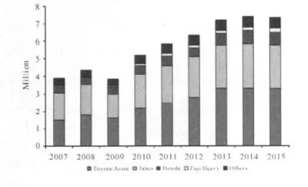
Figure 1 Volume of CVTs worldwide[2]
Nissan[3]has conducted a very interesting investigation to evaluate the convenience of different transmission types depending on the fuel consumption cycle.For this purpose the change in the vehicle speed in the cycle was calculated.Subsequently the fuel consumption was simulated in different cycles.
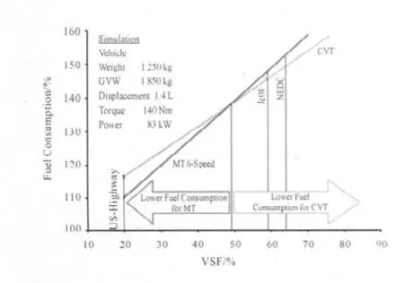
Figure 2 Fuel consumption in different cycles
The chart below shows that at a change in speed of over 48% generates an advantage for the CVT in comparison to a manual 6-speed transmission.The increasing time under share of part load leads to an optimization in fuel consumption due to the improved operating points of the engine.Unfortunately,the behaviour of customers in Europe or Germany don’t necessarily relate to the New European Driving Cycle(NEDC).Customers will therefore not currently experience the advantage in con-sumption.It remains to be seen whether the increasing urbanization leads to a convergence of the real driving behaviour towards the velocity profile of the fuel consumption cycle.
2 Performance
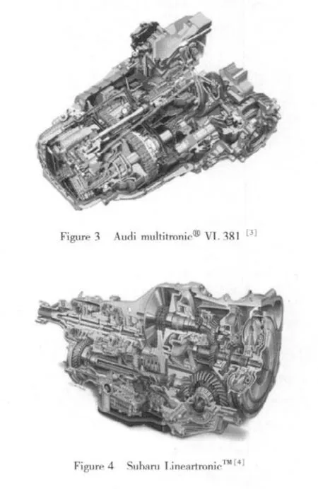
The focus until now has been not only on improved efficiency but also on increased torque capacity.As before,quality and reliability form the basis for success in the market.The new volume-produced CVT applications demonstrate how the aforementioned requirements have been implemented(Figures 3 and 4).
In conjunction with gasoline and diesel engines,it is already possible using LuK CVT technology to achieve up to 400 N·m at power levels of up to 220 kW.When these values are set against the competition,it can be easily seen what progress has been a-chieved in development.Figure 5 shows the product of torque and ratio spread as a function of the power related to the centre distance.In conjunction with the most powerful application,the Subaru LineartronicTM,it can be seen where the benchmark currently stands.
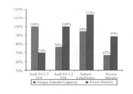
Figure 5 Benchmark CVT
What should the CVT of the future looks like?One possible answer is a modular transmission concept that allows the specific requirements of customers to be implemented in growing markets.The objectives must be higher efficiency,reduced costs,a smaller design envelope and lower weight.As a part of the discussion on CO2,the drive train must also be suitable for hybridization and stop/start.
The Japanese market demands a technical solution that comprehensively addresses the key issues of comfort and efficiency.In this case a transmission without a torque converter is difficult to imagine.In Japan,electro hydraulic clamping and control systems have been under development for several decades and have proved themselves in the market and with end customers.These systems are predominantly combined with single piston systems to achieve pressure.Further advantages can be reached,however,by expanding this method to include appropriate clamping strategies.The use of the LuK CVT chain also gives a range of advantages for power density and efficiency.On the other hand,there is a certain disad-vantage in acoustic terms.Experience has shown that this can be compensated by the use of efficient and easily comprehensible insulation measures in the vehicle in order to fulfill the expectations of end customers,especially in the case of small vehicles.
The markets in China and India are currently oriented primarily towards price and reliability of transmissions.In these locations,however,increasing importance will be attached in future to efficiency and fuel consumption.The“High-Value CVT”concept below has been specially developed for these markets.Due to platform strategies,it is necessary to introduce different vehicle concepts within one vehicle platform in all markets.The transmission concept must therefore allow easy adjustment of the transmission ratio as a function of the permissible vehicle weight.
3 The transmission specification
The transmission is intended to cover a wide spectrum of vehicles,from passenger vehicles to minibuses based on an A-Platform.The power and torque levels of 73 kW and 150 N·m correspond to the stated vehicle class.The vehicle weight varies,depending on the design,between 1 000 and 1 500 kg.An overall starting ratio between 14 and 19 is intended to ensure that all applications achieve the required traction force while using different starting elements.A factor of great importance is the overall length of the transmission,which was limited to a maximum of 300 mm.Furthermore,a specified target price below that of a conventional automatic trans-mission for the continuously variable transmission should fulfill the potential customer’s expectations as envisaged.
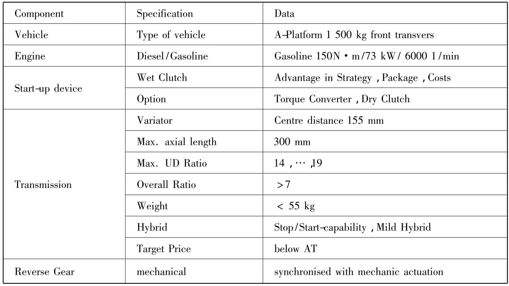
Table 1 Key data
4 High Value CVT hybrid
The transmission concept has to allow the use of various starting elements.Depending on the market and input torque,this may be a dry or wet starting clutch.In the comfort-oriented markets,the torque converter will continue to be the first choice.The High Value CVT envisages the use of a wet clutch as a starting element.The particular advantage lies in the strategic capability of the starting element.The input clutch can,in principle,be operated by electromechanical or hydraulic means.Appropriate actuators are already envisaged within the development framework of the automated manual transmission and for double clutch transmissions.
The torque sensor has proven itself in many applications.In conjunction with small,super-charged engines,it ensures an optimum setting of the clamping pressure.For the High Value CVT,a new type of five-stage torque sensor was developed which will be discussed in more detail later.In the stated markets,it should also be assumed that drivers must also travel on poor roads.It is therefore all the more important to avoid conditions where damaging slip occurs between the chain and the pulley surface.This has been taken into consideration in the design of the hydraulic system.
The pulley set has a double piston on the primary pulley set and a single piston on the secondary pulley set.Due to the improved piston surface design,the maximum pressures and the design envelope can be minimized and the pump size optimized at the same time.Furthermore,the design ensures that the clamping pressure remains the determining pressure in the system over wide ranges.This gives a further advantage in terms of fuel consumption when using the torque sensor in the pressure system.
In conjunction with the newly developed 07th chain type,the centre distance of 155 mm allows an overall ratio of 7.7.This large overall ratio ensures that the engine operates close to its optimum and thus allows low consumption.
As part of these considerations,a pulley set made from sheet metal components was developed,allowing significant reductions in costs and weight.The fixed and movable sheaves are made from sheet metal components joined by friction welding and are in some cases connected to cold formed shafts by means of press fits.This design reduces the weight of the pulley sets while retaining high rigidity.
The concept(Figure 6)was designed that the electric motor could be placed in the existing envelope without any changes at the housing.The electric power is about 11.5 kW.
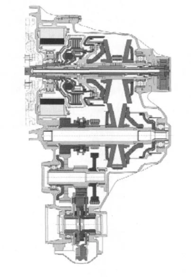
Figure 6 High Value CVT
4.1 Output stage/reverse gear
On the output side,a spur gear transmission is envisaged that allows a maximum ratio between 14 and 19.With this design range,it should be possible to achieve the necessary starting traction force or hill climbing ability for all vehicles based on one platform.The output stage allows the integration of the reverse gear in conjunction with a synchronization unit,dog clutch or multi-disk clutch.
4.2 Lightweight differential
The lightweight differential is designed as a spur gear differential.Significant components such as the planet carrier are designed as sheet metal parts in order to allow economical,optimized weight solutions.As a further advantage,this arrangement allows the use of sufficiently long drive shafts.
4.3 The clamping system
The simplest system envisages,as previously mentioned,the use of identical pulley sets on the primary and secondary pulley set in combination with an electronic clamping system.Since there are now almost 1.5 million Audi multitronicⓇtransmissions in the market,the advantages of the torque sensor for adjusting the clamping pressure have been successfully demonstrated on a broad basis.The essential advantage lies in the reliable recording of the drive torqueespecially in the low-load range significant for consumption and the precise and dynamic adaptation of the adjustment of the clamping pressure to the specific situation.
In conjunction with small supercharged engines,the resulting less precise torque signals and the sometimes poor roads in the emerging markets,the torque sensor represents a significant component in increasing reliability.
The further increase required in torque capacity has required necessitated the development of the fully variable torque sensor(vTS).The sensor adapts the clamping pressure in an optimum manner to the clamping requirement of the variator.However,this is a technically complex variant and accordingly does not represent the most cost-effective solution.Possibilities were sought for achieving a more cost-ffective variable torque sensor during the development of the multitronicⓇ.
5 The orifice torque sensor
The orifice torque sensor(OTS)is based on the economical,two-stage torque sensor(2TS).Its fivestage design makes it possible to significantly reduce excessive clamping pressure.For example,the clamping pressure in the ratio range 0.40<iVar<0.68,which is significant for consumption,was reduced by 8%compared to the 2TS.In addition,the maximum load on the pulley set shafts in particular is significantly reduced,which allows smaller cross-sections to be used with corresponding advantages in terms of weight and ratio spread.
The costs are at approximately the same level as those of the established two-stage torque sensor.It is realized by using orifices B1 to B4(Figure 7)in the primary pulley shaft.Depending on the position of the movable pulley,a different number of orifices are released and the clamping pressure is set accordingly.The function of the OTS is confirmed by comprehensive tests on a test rig and in the vehicle(Figure 8).For front end transverse applications,the design can also be config-ured so that the torque sensor does not determine the overall length.In this case,the balls and ramps are arranged within the multi-disk clutch in order to give a shortened pulley set and achieve the required overall length(Figure 6).

6 Hydraulic system
The hydraulic system supplies the functions of clamping,adjustment,clutch actuation,clutch cooling and cooling of the pulley sets.The oil,conveyed by the pump,flows via a pressure control valve(VVS1)and a differential pressure valve(VSS2)to the torque sensor,which operates in the established manner as pressure control valve.After the torque sensor,this oil is used directly for cooling of the clutch.The system offers the option of varying this volume flow by directing portions of the oil parallel via the volume control valve and a minimum pressure valve(VMD)back to the suction tract of the pump.Ahead of the VMD,the oil is branched off for cooling of the pulley sets and for lubrication.
The variability of the volume flow to the torque sensor ensures a minimum supply on the one hand and also reaches the minimum requirement for cooling of the clutch.On the other hand,it is also possible to provide a high volume flow for maximum clutch cooling.The system pressure is determined primarily by the torque sensor.Where a higher system pressure is required for adjustment,an increase can be managed by VVS1 or VSS2.The pressure reduction valves VKSI,VKA and VSS1 are connected to the system directly after the pump and draw off the pressure oil that they require to supply the functions controlled by them.The VSS1 adjusts the pressure in the adjustment chamber 1 and thus provides the support of clamping force ratio or the change of variator ratio,which itself requires an additional axial force on primary pulley set.The pressure is also used as a control pressure for VVS1 in order to increase the system pressure as required.The VKA adjusts the clutch pressure.If an error occurs,the VSI can reduce the clutch pressure en route to the clutch.The VKSI sets a pressure for controlling of the VKK.The VKK varies the control value for the VQP and thus achieves the aforementioned control of the volume flow.The VKSI pressure is also used for switching of the VSI.The clamping pressure in the single piston of secondary pulley set is also specified by the torque sensor.In order to get a certain clamping force ratio or adjust-ment,in which an additional axial force on the secondary pulley set is required,this pressure must be increased above the torque sensor pressure.The differential pressure valve VSS2 is arranged between the single piston on secondary pulley set and the clamping pressure chamber on primary pulley set or the torque sensor.Thus it is able to set a higher pressure in secondary pulley set than that specified by the torque sensor.
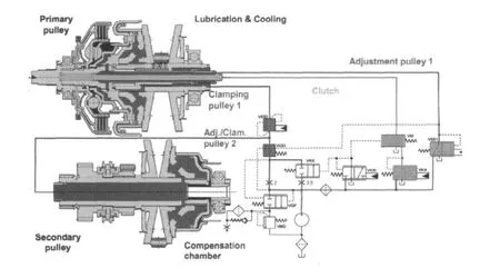
Figure 9 Hydraulic layout
7 High Value CVT em
Engine power is increasing in the scooter,snowmobile and ATV sectors.With dry CVTs,the amount of power cannot be transferred without restrictions in performance.For this purpose the High Value CVT em with electromechanic clamping and adjustment system was investigated.The targeted torque capacity for up to 150 N·m is sufficient even for small passenger cars.
The clamping and adjustment is realized by electric motors in combination with planetary gear sets with rolling contacts.The necessary power of the electric motor is about 1 kW on the primary side and below 1 kW on the secondary pulley.
It can be expected that the efficiency is significantly improved compared to the dry system.However,the improvements are not limited to efficiency,since emissions will be also reduced.In addition,the reliability of the system was improved compared to that of existing solutions.
The design of the module in the sheet metal housing to handle the forces facilitates easy installation of the variator system.Both pulley sets can be completely identical.The size is determined by torque capacity and overall ratio.
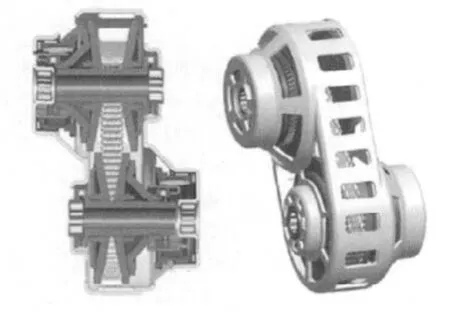
Figure 10 High Value CVT em
8 The new chain portfolio
LuK uses traditional chains for CVT.In addition to the functional advantages of the chain,there is a significant benefit from their modularity.Due to their construction of link plates and rocker pins(Figure 11),the chain can easily be matched to the loads and geometrical boundary conditions of the specific application.The previous applications of the LuK CVT chain were mainly found in the moderate and upper torque range and were covered without exception by the chain type 08.In the course of discussions on increasing the power density of the subassemblies,the further development of“small”chains was driven forward and a very high performance capacity was identified.The aim here is to combine the advantage of the chain(efficiency,robustness,large overall ratio and improved acoustics spread,etc.)with the further potential of a smaller geometry.
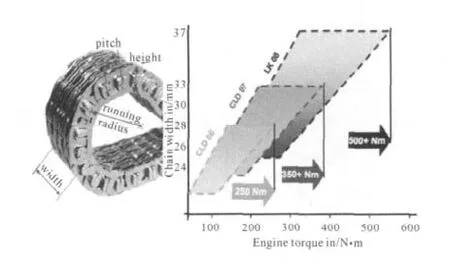
Figure 11 Modular chain system
Irrespective of size,LuK CVT chains have also undergone further development of the design.One development item,for example,is the optimization of the contact conditions between the chain and the guide rail.The function of the guide rail is to suppress strand oscillation effects and is in contact with the outside profile of the links during operation.
The outside profile of previous chains had cams in order to provide secure location of the links during assembly.During the course of further development,these were replaced by dents in order to prevent possible pitting effects on the guide rail.This optimization is of course neutral in terms of strength and can be applied to all the types and sizes of chains under consideration here.
Chain type 07
The chain type 07 represents,in simplified terms,a scaling down of the type 08 with additional detailed optimizations.The use of type 07 gives primarily geometrical advantages that are reflected,for example,in a reduced design envelope or a significant increase in overall ratio(Figure 12).
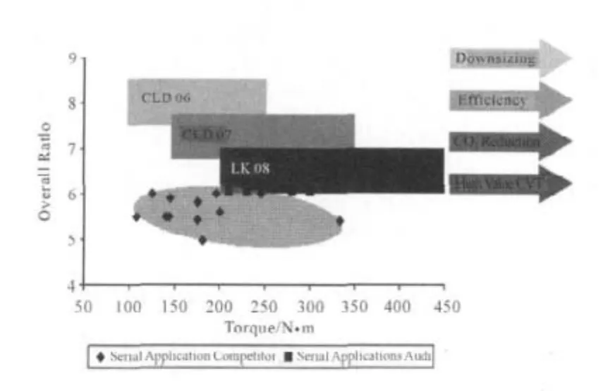
Figure 12 Overall ratio of chain types
In order to make use of these advantages,the small chain must fulfill the necessary strength requirements.Tests carried out show that the chain type 07 allows transmission of high torques and has the potential to replace chain applications with large pitch across wide areas.
Chain type 06
As described in the preceding section,a reduction in the size of the chain type(transition from 08 to 07)brings a series of possible advantages.One interesting question now is to what extent it is advisable to reduce the size of the chain further.In order to answer this question,an even smaller version of chain type 06 was designed and assessed using simulations.As the individual parts become smaller,their strength decreases first.On the other hand,this leads to effects that can have a positive influence on the loading of the chain.Where a smaller chain pitch is present,for example,the frictional force between the chain and pulley set is split between a larger number of joints.This leads to more uniform load distribution.
Once all these conditions are taken into consideration,the chain type reduced in size by 10%(transition from 07 to 06)can be expected to show the performance capacity shown in Figure 13.In terms of chain width,it achieves approximately the performance capacity of chain type 07.As a result,this chain is virtually the obvious choice for passenger car applica-tions with low or moderate torque values or even for applications in the two-wheel sector.A decisive motivation in reducing the size of the chain is the possibility of influencing acoustic characteristics.The chain 06 offers not only a reduced weight but also a significantly lower chain pitch,which gives a reduction in the excitation level due to polygonal running.Further-more,the smaller pitch changes the excitation frequencies.The acoustic effects of this new chain must be assessed in an actual environment and a further improvement in the acoustic behavior compared to previous chains can be assumed.
9 Assessment of the High Value CVT on the NEDC
The efficiency optimizations described in previous sections for the High Value CVT were assessed in relation to consumption on the NEDC.The boundary conditions selected for simulation included the following vehicle and drive train parameters:
Vehicle weight:1 200 kg(A-Platform)
Engine specification:73 kW/150 N·m petrol
High Value CVT:overall ratio 7.7/starting ratio 14.5/overdrive ratio 1.9
For comparison purposes,a drive train with a 5 speed manual transmission(MT)was selected that corre-sponds to the current level of technology in this weight and power category.The starting ratio used in the MT is 15.6,while the overall ratio in the highest gear is 3.7.This gives an overall ratio of nearly 4.3.In addition,the drive train was investigated with a manual transmission of the following variants,in order to cover the latest trends:
5 speed MT with gearshift recommendation
5 speed MT with gearshift recommendation and differential ratio 10%higher
High Value CVT hybrid
The latter variant is suitable for presenting a comparison with a manual transmission for op-timized consumption.With an overall spread of 4.3 it is not possible,however,to increase the axle ratio by more than 10%without having to accept disadvantages in terms of starting dynamics,acceleration and hill climb ability.In contrast,the High Value CVT with an overall ratio of 7.7 achieves not only good acceleration values but also reduced fuel consumption due to an overall ratio in overdrive of less than 2.This advantage is reflected in the simulated NEDC consumption,which is shown fordifferentvariants in Figure 13.

Figure 13 Simulation of consumption on NEDC for High Value CVT compared with 5 speed MT
10 Conclusion
CVT is an established part of the automotive world,with the current focus undoubtedly in the Asiatic region.Starting from these markets and sustained by new,interesting applications,a further increase in market share can be anticipated for the future.The High Value CVT concepts show a high potential even for small vehicles to realize a cost efficient,comfortable and efficient automatic transmission.In comparison to manual trans-missions,savings above 5%can be expected without hybridization.The combination between CVT and hybrid is the optimal technical solution for the hybrid drive train.The electromechanical system offers further possibilities for reducing losses and is the solution for applications in all kinds of small vehicles with 2 or 4 wheels.With the new chains LD 06 and LD 07 it is possible to support downsizing concepts in an optimal way.At the same time,the acoustic behaviour of the chain can be further improved.In the course of the trend of increasing urbanization,the chain CVT still offers an outstanding technical solution with high value.
[1]Auto Industry Analysis Report No.743[EB/OL].[2009-01-23].www.marklines.com.
[2]www.csmauto.com.
[3]Yoshikazu Oota.The advantage of CVT in the real world[M].CTI Berlin:[s.n.],2009.
[4]www.audi.de.
[5]www.subaru.de.
[6]Teubert A,Englisch A,Götz A,et al.LuK CVT Technology-Efficient,Comfort,Dynamic,Transmission in Vehicles[M].Friedrichshafen,[s.n.],2009.
[7]Englisch A,Faust H,Homm M,et al.CVT without limits-Components for Commercial vehicle,8[Z].LuK Symposium,[s.n.],2006.
[8]Faust H,Linnenbrügger A.CVT-Development from LuK,6[Z].LuK Symposium,[s.n.],1998.
[9]Teubert A,Linnenbrügger A,Nakazawa T,et al.LuK CVT Components for Future Efficient Drivetrains[Z].Tokyo/Japan:JSAE Symposium,2008.
