Study of a Synthesized Unsymmetrical Optimal PWM Technique of Selective Harmonic Controlling for Cascaded H-Bridge Multi-Level Inverters
2011-06-06
(1.Wuhan University Wuhan 430072 China 2.Naval University of Engineering Wuhan 430033 China)
1 Introduction
Nowadays the application range of power electronics technology is going in the field of utility apparatus in power system towards the multi-Mega watt power level,for example,with flexible alternative current transmission systems (FACTS)devices.
Generally,different pulse width modulation methods are widely used[1-8],but in the application of FACTS because of the constraints of switching semiconductor,then the switching frequency,pulse pattern and switching losses are of great concerns for these applications.
Up to now a large number of pulse patterns optimized according to different criteria have been presented.The first idea was presented by Patel and Hoft[9]as selective harmonic elimination (SHE)method,by which the fundamental component is controlled and further harmonics are eliminated.This method is very suitable for electrical drives,but it is not able to generate harmonics for injection of harmonics in power grid applications.
Nowadays some specific harmonics can be generated according to amplitude and phase angle reference only by space vector modulation with switching frequencies of some kilohertz.Unfortunately in the power range of FACTS technology with high power up to tens of Megawatts,the switching frequency is limited to a few hundred Hz up to 1 kHz.
In order to meet the constraints of low switching frequency for high power inverters with multi-Mega watt power level,and the control of fundamental voltage component and harmonics in amplitude and phase angle simultaneously with low switching frequency,one side,an unsymmetrical optimal PWM technique was proposed for single polar output inverters[10]to control the fundamental component and some specific harmonics in a few hundred Hz selectively.Therefore specific harmonics can be generated and injected into the power grid by PWM VSI at relatively low switching frequency.The reason for some specific harmonics injection for compensation selectively is explained for as high as possible system stability and compensation precision[11].On the other side,multilevel inverters have caused great concerns because of their capability of high voltage operation,high efficiency,and low electromagnetic interference[12-13].So this leads to low switching losses,and because of several DC sources,the switching conductor undertakes a low dv/dt.Then the multi-level cascaded inverter technology is a prospective topology for high power electronics device for utility applications,such as FACTS.
In generally studying a modulation strategy of a PWM inverter is a tradeoff between switching frequency and harmonic distortion.Therefore the aim of this paper is to propose a synthesized unsymmetrical optimal PWM technique of selective harmonic controlling with the mean frequency as lowest as possible.The reason of sharp reduction of mean switching frequency is the reduction of dynamic switching losses almost linearly with this switching frequency.The prospective advantages of the proposed technique of controlling some specific dominant harmonics are damping system oscillation and avoiding system resonance.
2 Principle of a synthesized unsymmetrical optimal pulse width modulation technique
Generally the optimal pulse pattern A owns half-wave mirror symmetry and quarter wave symmetry as a simple example in Fig.1a,it is extensively used for selective harmonic elimination(SHE),but it can only control the amplitude of a harmonic with one freedom of degree of switching angle.Recently an optimal pulse pattern B was firstly proposed as a simple example in Fig.1b.It owns only half-wave mirror symmetry,but it gives up the quarter symmetry.It can control the amplitude and phase angle of a harmonic with two freedoms of degree of switching angles.It is proposed as an optimal pulse pattern with unsymmetrical switching angles,namely OPUS technique.
The basic idea of this proposed optimal pulse pattern is demonstrated by adding the above two kinds optimal pulse patterns,namely the optimal pulse pattern A synthesized with optimal pulse pattern B in Fig.1c.According to this proposed optimal pulse pattern,the proposed optimal synthesized PWM technique will be explained how it controls effectively specific dominant harmonics for cascaded multilevel inverters simultaneously.
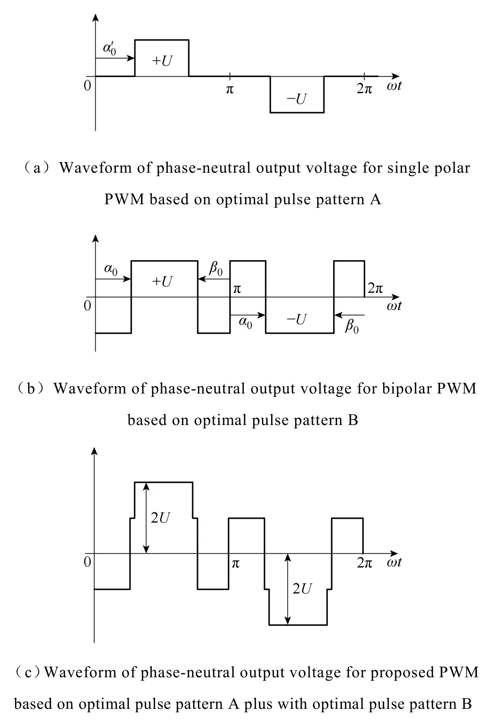
Fig.1 Principle of a proposed synthesized unsymmetrical optimal pulse pattern
The comparison between SHE method,OPUS technique and proposed synthesized optimal PWM technique is shown by a case of controlling fundamental,5th,7th,11th,and 13th harmonics in Tab.It is obviously that SHE method can’t be controlled the phase angle of the dominant low order harmonics.Though OPUS technique can be used to control the fundamental and harmonics with their amplitude and phase angle directly,it has heavy calculation burden to solve a 10 dimensional transcendent equations for the given case in Tab.

Tab.Comparisons of variable freedoms of degree between SHE method,OPUS technique and proposed PWM technique
For easy explanation given that one dominant harmonic,for example the 5th harmonic,must be controlled,the basic principle of the proposed optimal PWM technique is the following.
Firstly,5 inverter units controlled by the single polar SHE method with 5 freedoms of degree can be used to control the fundamental,and the 5th,7th,11th and 13th harmonics to be eliminated.
Secondly,the OPUS technique with two freedoms of degree is applied to control one inverter unit for the fundamental with its amplitude and phase angle.In order to control as lowest as possible parasitic harmonics,the fundamental frequency is transferred to the desired 5th harmonic of dominant harmonics.Therefore it is obvious that the mean switching frequency 750 Hz in Tab.1 for an inverter unit controlled by bipolar OPUS PWM will be explained.
Finally the generated desired harmonic controlled by OPUS technique can be added and synthesized with the output voltage controlled by SHE method.
In order to realize the above case of harmonics controlling,it is shown that the former 10 dimensional transcendent equations of OPUS technique can be simplified with the 5-dimensional equations controlled by SHE plus two dimensional equations of OPUS technique for the proposed optimal PWM technique (shown in Tab).Therefore,the advantages of these two methods can be combined together for the proposed method in this paper.
3 Proposed PWM technique for harmonic controlling selectively and synthesizing for multilevel inverters
3.1 Finding switching angles to eliminate some specific harmonics for pulse pattern A
A three phase topology circuit of a cascaded H-bridge multilevel is shown in Fig.2a,there are two types of voltage output of H-bridge topology circuits,one type is for bipolar modulated PWM phase voltage output (-U,U),which is shown by unit model with gray shade.The reason of choosing an inverter unit of bipolar phase voltage output will be explained in the following text.The other type is for single polar modulated PWM phase voltage output,which is shown by unit model without shade,then each inverter level can generate three different voltage outputs,+U,0 and –U.
The single polar phase voltage output waveform is synthesized by the sum of three inverter units of voltage outputs shown in Fig.2b.The control of the multilevel inverter is to choose a series switching angles to synthesize a desired sinusoidal voltage waveform.Each cascaded H-bridge inverter unit voltage output is controlled by single polar PWM with 50 Hz of switching frequency.
Generally,due to the quarter wave symmetry of the above pulse pattern A along thex-axis,both Fourier coefficientsa0andanare zero.The Fourier series expansion of them-level voltage waveform is shown in Eq.(1).

For a three-phase application,the triple harmonics in each phase need not be cancelled because they automatically cancel in the line voltage.For example,in the case of five units of dc source,usually the low order 5th,7th,11th and 13th harmonics can be cancelled.
The switching angles can be found by solving the following Eq.(2):

Where,M1=π·b1/(20U) defined for the modulation ratio of fundamental component.
The optimal process of the fundamental component for the multilevel inverter is the following.
Firstly,the phase voltage output with the same amplitude and phase angle is controlled for each cascaded H-bridge inverter unit.
Secondly,the conducting anglesαj(j=1~5)are chosen so that the total harmonic distortion of the phase voltage is minimized.
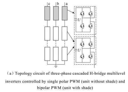
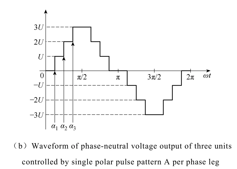
Fig.2 Phase-neutral voltage output of multilevel inverters synthesized by single polar optimal PWM
Thirdly,the above transcendental equations are calculated by an iterative method with software MATHCAD.
Given that the fundamental modulation ratio of the phase voltageM1=0.8,the results of the switching angles are the following:

The obtained FFT analysis for the output line voltage (van/U,Fig.3a) according to the above conducting angles is shown in Fig.3b.It means that the fundamental component is controlled asM1=0.8,and the 5th,7th,11th,13th harmonics are eliminated.

Fig.3 Phase-neutral voltage waveform and its harmonic modulation performance
3.2 Finding switching angles for controlling specific harmonic by unsymmetrical optimal pulse pattern B
As the same way,due to the wave form with only the half-wave mirror symmetry along thex-axis in Fig.1b,so the Fourier series are the following Eq.(3):

For example,in order to generate the specific 5th harmonic according to its amplitude and phase angle for the purpose of selectively harmonic controlling,then controlling the fundamental with its amplitudec1by fundamental modulation ratioM1and phase angleθ1are defined as the following Eq.(4):

The switching anglesα0,β0are calculated and obtained for determining the fundamental voltage with a predefined per unit voltage by software MATHCAD according to the following Eq.(5):

Now the reason of choosing an inverter unit of bipolar PWM phase voltage output is for calculating out the switching angles for a specific fundamental component (M1=0.8) with its phase angleθ1ranging from 0°to 2π for Eq.(5) in Fig.4a.And if the topology circuit for single polar PWM phase voltage output is chosen,unfortunately the similar calculation result such as in Fig.4a will not be calculated out forθ1ranging from 0 to 2π.The switching angles shown by a three dimension diagram with parameter variables forM1ranging from 0 to 0.95 andθ1ranging from 0 to 2π in Fig.4b are given.
Given the desired fundamental withM1=0.8,θ1=60°,soα0=12.32°,β0=64.97°are calculated,then the period of output phase–neutral voltage output is transferred to 1/5 original time period (Fig.5a).Therefore,the original fundamental component is transferred and moved to the 5th harmonic withM5=0.8 andθ5=60° for the purpose of selectively harmonic controlling (Fig.5b).Then the parasitic harmonics is as lowest as possible.

Fig.4 Trajectory of unsymmetrical switching angles calculated and controlled by proposed optimal pulse pattern B

Fig.5 Principle of control of a specific harmonic by waveform transforming
4 Results of proposed PWM technique for controlling both fundamental and a specific harmonic
Synthesizing the former two kinds of modulated phase voltage output controlled by both SHE method and OPUS technique together,it means that there are five units of cascaded H-bridge inverters output voltage controlled by SHE method and one unit inverter controlled by OPUS technique separately; the sum of each unit output of phase voltage (van/U) is shown in Fig.6a.For example,a modulation ratio is chosen as 0.8 for fundamental and the 5th harmonic separately; therefore it is shown that the component ration between the 5th harmonic and the fundamental is 20% in Fig.6b.From Fig.6b the modulation control range for the 5th harmonic is maximal to 0.95 with high modulation efficiency for a specific harmonic controlling.This is the advantages for the proposed technique specially.And the active power,reactive power and the 5th harmonic can be controlled simultaneously with relative low switching frequency,the lowest order of non-controllable harmonic is the 17th harmonic.For the control of the other dominant low order harmonic,such as the 7th,or 11th harmonic,it may be controlled in the similar way.Due to the parasitic harmonics above the 17th harmonic the method of passive harmonic compensation can be used,but no discussion here.
5 Conclusions
A synthesized unsymmetrical optimal PWM technique was proposed for reducing the calculation burden by decreasing the dimensions of the transcendent

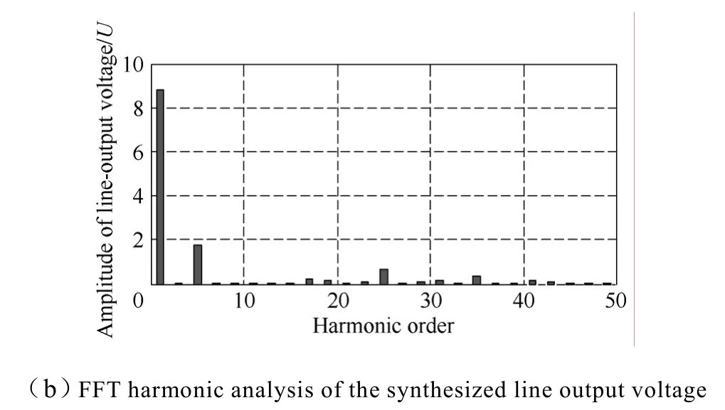
Fig.6 Line-voltage output of the proposed synthesized unsymmetrical optimal PWM technique and its selective harmonic modulation performance
equations in this paper.The harmonic control range of the proposed PWM technique and the off-line calculation of switching angles are given.The performances of fundamental and a specific harmonic controlling of this proposed technique are demonstrated by simulation results.
Reference
[1] Abu-Rub H,Holtz J,Rodriguez J,et al.Medium-voltage multilevel converters—state of the art,challenges,and requirements in industrial applications[J].IEEE Transactions on Industrial Electronics,2010,57(8):2581-2596.
[2] Bowes S R,Holliday D.Optimal regular-sampled PWM inverter control techniques[J].IEEE Transactions on Industrial Electronics,2007,54(4): 1547-1559.
[3] Rodriguez J,Pontt J,Kouro S,et al.Direct torque control with imposed switching frequency in an 11-level cascaded inverter [J].IEEE Transactions on Industrial Electronics,2004,51(4): 827-833.
[4] Sundareswaran K,Jayant K,Shanavas T N.Inverter harmonic elimination through a colony of continuously exploring ants[J].IEEE Transactions on Industrial Electronics,2007,54(5): 2558-2565.
[5] Cho K M,Oh W S,Kim Y T,et al.A new switching strategy for pulse width modulation (PWM) power converters[J].IEEE Transactions on Industrial Electronics,2007,54(1): 330-337.
[6] Beig A R,Narayanan G,Ranganathan V T.Modified SVPWM algorithm for three level VSI with synchronized and symmetrical waveforms[J].IEEE Transactions on Industrial Electronics,2007,54(1): 486-494.
[7] Etxeberria-Otadui I,Viscarret U,Caballero M,et al,New optimized PWM VSC control structures and strategies under unbalanced voltage transients[J].IEEE Transactions on Industrial Electronics,2007,54(5): 2902-2914.
[8] Gonzalez S A,Garcia-Retegui R,Benedetti M.Harmonic computation technique suitable for active power filters[J].IEEE Transactions on Industrial Electronics,2007,54(5):2791-2796.
[9] Patel H S,Hoft R G.Generalized techniques of harmonic elimination and voltage control in thyristor inverter: Part I—Harmonic elimination[J].IEEE Transactions on Industry Application,1973,IA-9(3): 310-317.
[10] Zhang Hui,Liu KP,Braun M,Chan C C.Selective harmonic controlling for three-level high power active front end converter with low switching frequency[C].Proceedings of the CES/IEE 5th International Power Electronics and Motion Control Conference,2006.
[11] Lascu C,Asiminoaei L,Boldea I.Frequency response analysis of current controllers for selective harmonic compensation in active power filters[J].IEEE Transactions on Industrial Electronics,2009,56(2):337-347.
[12] Du Zhong,Tolbert L M,Chiasson J N,et al.Reduced switching-frequency active harmonic elimination for multilevel converters[J].IEEE Transactions on Industrial Electronics,2008,55(4): 1761-1770.
[13] Rodriguez J,Lai J S,Peng F Z.Multilevel inverters: a survey of topologies,controls,and applications[J].IEEE Transactions on Industrial Electronics,2002,49(4): 724-738.
