阳极氧化铝模板法可控制备金属纳米线和纳米管阵列的生长机制
2010-12-12郭元元毛晓波蒋月秀杨延莲
郭元元 汪 明 毛晓波 蒋月秀 王 琛,* 杨延莲,*
(1广西大学化学系,南宁 530004; 2国家纳米科学中心,北京 100190)
In recent years,one dimensional(1D)nanostructured materials, including nanowires,nanotubes,and nanorods,have attracted considerable attention because of their novel physical properties and potential applications in nanodevices,such as carbon[1-2], metals[3-5],metal sulfides[6-7],metal hydroxide[8],metal oxides[9-10], polymers[11],and some organic molecules[12-13].A variety of strategies,such as direct catalyzed growth,templated growth,and self-assembly and so on,have been utilized for successful fabri-cation of 1D nanomaterials[14-16].Among these methods,the templated synthesis of 1D nanomaterials using the anodic aluminum oxide(AAO)is an effective venue for fabricating nanotubes and nanowires of metals,metal oxides,fullerenes,organic molecules[17-19],as well as metallic 1D nanomaterials[20-22].The well-defined length and diameter of the AAO channels facilitate controlled fabrication of 1D nanostructures.Chemical replacement[23],chemical infiltration[24],chemical vapor deposition(CVD)[25],and electrochemical deposition[26-27]have been utilized for preparation of 1D nanomaterials within the porous alumina template.Among these techniques,electrodeposition method was widely used for preparing metallic and semiconducting nanowires,such as Ni, Cu,Au,Ag,bimetallic nanowire junctions for magnetic,catalytic applications[28-29].It could be noted that metal nanotubes are considered very promising for high performance catalysts[30-31],highly sensitive gas sensors[31-33],and up-conversion non-linear optics[34], etc.Thus,many efforts have been put into the controlled synthesis of metal nanotubes.As a general approach to fabricate well-defined metal nanotubes,the inner surfaces of the AAO channels are usually chemically modified with suitable functional groups-molecular anchors[35-36],so that the electrodeposited metal atoms can bind to the nanopore walls to form nanotubes. A number of metallic nanotubes have been successfully synthesized by this method,while the unavoidable organic impurities introduced from the chemical modification process limited its applications[37-38].Metal nanotubes can also be obtained by controlling the thickness of the electrode film for preventing the pores from being blocked[39-40]and followed by electrodeposition of the metals[41].The fabrication via multi-step template replication and electrodeposition approach was also reported to get metal nanotube array[42].
Fundamentally the growth of metal nanotubes and nanowires is governed by the electrochemical deposition process and the concentration diffusion of the metal ions.The understanding of the growth mechanism would benefit the controlled fabrication of desired metal nanostructures for specific applications.Some reports have attributed the nanotube growth to the well-known tip effect[43-44].Recently,Yoo et al.[20]proposed the bottom-up and the wall-up growth modes to describe the metal nanotube formation,and also reported the preparation of Pt and Pd nanotubes by a wall-up growth mechanism at high current density.Cao et al.[45]also reported the controlled preparation of metal(Fe,Co, Ni)nanotube arrays and proposed a mechanism of competitive growth rates along two directions:parallel to and perpendicular to the current direction.The mechanisms proposed by Yoo[20]and Cao[45]et al.can be considered principally the same.In addition,Chowdhury et al.[46]put forward the mechanism related to overpotential increase by gas evolution for the central portion shielding and thus the promotion of the reaction at the sides of the porous templates.Common to these studies is that the nanotube formation is dependent on the different growth rates of the metal along the wall surface(Vw)and from the central bottom of the nanochannels(Vb),while systematic studies are still needed to fully understand the growth mechanisms which are critical for controlled growth of nanowires and nanotubes.In this work,we examined the controllable synthesis of Ni nanowires and nanotubes by electrodeposition method using AAO as template. Based on the systematic studies,mechanisms for the nanowire and nanotube growth were proposed.
1 Experimental
1.1 Templated electrodeposition
The AAO templates used in our experiments were purchased from Whatman Company(Anodisc 47,200 nm in nominal pore diameter and 60 μm in thickness).The electrodeposition was carried out with the constant potential mode in a conventional three-electrode electrochemical cell.Before the electrodeposition,Au film was first deposited as an electrode on one side of the AAO membrane using a vacuum evaporation apparatus and a small portion of the inside channels were filled to shape a bowl-like structure[4,43].AAO template coated by Au layer,a piece of platinum plate(ca 1.0 cm2),and a calomel electrode were used as the working,counter,and reference electrodes,respectively. All the electrodeposition experiments were performed at room temperature and the deposition time was kept constant at 1000 s.
The electrochemical deposition was conducted in aqueous solutions containing NiSO4·6H2O(AR),ethylenediaminetetraacetic acid(EDTA,AR),NaOH(AR),and K2HPO4(AR).The concentration of EDTA was two times higher than that of the Ni2+ions.The concentration of K2HPO4was kept constant at 20 g·L-1and the pH values were adjusted by NaOH to 11 for the solutions with EDTA.All the solutions were prepared with ultrapure Milli Q water(resistivity≥18 MΩ·cm).The electrodeposition was performed at room temperature and the detailed electrodeposition conditions are shown in Table 1.
1.2 Characterization of Ni nanowires or nanotubes
After electrodeposition,the AAO templates were removed by immersion in 2 mol·L-1NaOH solutions at 25℃for 2 h.Then,the as-prepared samples were thoroughly rinsed with distilled water and subsequently dried in air.Scanning electron microscopic(SEM)characterizations of the products were performed on a Hitachi S-3400N SEM apparatus.For transmission electron microscopic(TEM)characterizations,the samples were subjected to ultrasonic treatment in ultrapure water for 1 min,then a drop of suspension was dipped on the carbon-coated copper grid.All TEM characterizations were performed on an FEI TEM(Tecnai G2 20)at an accelerating voltage of 120 kV.X-ray photoelectron spectroscopic(XPS)measurements were conducted on an XPS spectrometer(VG Scientific ESCALab 220i-XL)operated at 300 W in vacuum(3×10⁻⁷Pa)with a monochromatic Al Kαradiation.The binding energies were corrected for charging by adventitious carbon(C 1s)at 284.8 eV.Curve fitting of the XPS spectra was performed by using XPS PEAK software.

Table 1 Electrodeposition conditions for preparing Ni nanotubes and nanowires
2 Results and discussion
2.1 Impact of chelating agent EDTA
Electrodeposition of Ni was conducted with the aid of the AAO template for the preparation of nanowire or nanotube arrays.All the samples were etched using NaOH solution for 2 h to remove the AAO membrane,thus the nanowires or nanotubes can be exposed from the template.The Ni nanowires can be obtained in the solution(the concentration of Ni ions,CNi2+=0.01 mol·L-1)without addition of EDTA at electrodeposition potential Ued=-1.5 V.SEM image in Fig.1(a)shows highly ordered Ni nanowire arrays with uniform structures in large area.The average diameter of the Ni nanowires is about 200 nm which resembles the pore diameter of the AAO template(200 nm).Upon the introduction of EDTA,nanotube arrays could be obtained with the same CNi2+(0.01 mol·L-1)and the same Ued(-1.5 V).SEM image in Fig.1(b)reveals the typical morphology of the highly ordered Ni nanotube arrays with clear open ends.The outer diameters of the nanotubes were around 200 nm(nearly the same as the pore diameter of the AAO template)and the inner diameters were around 140-160 nm.In other words,the thickness of nanotube walls was about 20-30 nm.The length of the nanotubes and nanowires could reach about 20 μm in 1000 s.

Fig.1 SEM images of Ni nanowire and nanotube arrays without and with EDTA(a)top view of the Ni nanowires deposited from the solution with CNiSO4=0.01 mol·L-1at Ued=-1.5 V;(b)top view of the Ni nanotubes deposited from the solution with CNiSO4=0.01 mol·L-1,CEDTA=0.02 mol·L-1,CK2HPO4=20 g·L-1at Ued=-1.5 V(sample 2)
The conversion of the nanowire to nanotube morphology with the introduction of the EDTA into the solution demonstrated the impact of the coordination ion on the eletrodeposition mechanisms.The growth of nanowires and nanotubes can be viewed as a balance between two dominated growth rates,Vwand Vb. The bottom-up and the wall-up growth modes proposed by Yoo et al.[20],and the current-directed tubular growth(CDTG)mechanisms proposed by Cao et al.[45],have revealed the relationship between the morphologies of the 1D nanomaterials and the current densities at different locations.However,the underlying mechanism for the relationship of the current densities and the growth rates is still need to be clarified.In the reduction process of nickel ions,nanotubes can be obtained if Vw>Vb.It should be noted that both Vwand Vbcould be affected by the introduction of the chelating agent EDTA,and the well-known tip growth effect should be also taken into account.The electrochemical deposition process of Ni with EDTA can be divided into three steps as following.
a)The coordination of Ni2+with EDTA.There are seven forms for EDTA in solution(H6Y2+,H5Y+,H4Y,H3Y-,H2Y2-,HY3-, Y4-)and their populations are dependent on the solution acidity. The complex NiY2-is the compound with the highest population when pH>10.The chelation and the dissociation balance of the complex can be described as below.
Ni2++Y4-⇌NiY2-
b)The diffusion of NiY2-and Ni2+ions to the surface of the electrode.When the Ni2+was depleted near the working electrode,it will be supplied by the dissociation of NiY2-.The concentration of Ni2+was limited in the range of 10-16mol·L-1,because the stability constant of the complex was 1018and the concentration of Y4-ions was kept in the range of 10-2mol·L-1.
c)At last,Ni2+receives electrons on the surface of the cathode and forms nanotubes or nanowires.As mentioned above,Au film deposited as a working electrode at the bottom of the AAO membrane with bowl-shaped structures[4,43].Because of the tip effect,the edge tips of the initial bowl-shaped Au electrode give rise to higher electric field,which is electrochemically more active than the smooth surface.Meanwhile,the surface energy of the inner walls of the nanochannels[48]also facilitates the bottom edge of the nanochannels to be a preferential site for the deposition of metal ions.Considering that the effective growth rate is correlated to the effective Ni2+concentration,the addition of EDTA would result in decreased reduction rate of NiY2-compared with that of the Ni2+hydrate.Both Vwand Vbwere greatly reduced by the chelating agent.At this slower reduction rate,the tip effect of the electric field would render the predominance of the higher deposition rate of Vw(Vw>Vb)and finally give rise to the formation of metal nanotubes.On the contrary,both of the growth rates(Vwand Vb)are very fast in the solution without EDTA,so the tip effect could be ignored(Vw≈Vb),thus the nanowires can be obtained.
2.2 Impact of electrodeposition potential and electrolyte concentration
The electrodeposition potential is a key factor for the formation of metal nanotubes and nanowires.When other conditions are constant,more negative Ued(higher than the potential for gas evolution)would lead to the higher current density which is keenly related to the growth rates,Vband Vw,thus the final morphology of the 1D metallic nanostructures.Meantime,Uedalso influences the electromigration rate of the NiY2-,which has the opposite direction to the concentration diffusion in the solution.
In order to further understand the growth mechanism for the formation of metal nanotubes and nanowires,systematic studies were performed under different conditions listed in Table 1.At a higher NiY2-ion concentration(sample 1),Ni nanotubes with thin wall could be gained at more negative Ued=-1.5 V.When the concentration of NiY2-decreases gradually(samples 1-4),at Ued= -1.5 V,the SEM images in Fig.2(a,d,e)clearly illustrate the evolution of the 1D nanomaterials from well-aligned nanotubes in sample 1,to coexistence of nanotubes and nanowires(mainly nanotubes)in sample 3 and finally to coexistence of nanowires and nanotubes(mainly nanowires)in sample 4.In addition,the gradual increase of the nanowire proportions is also accompanied by the gradual increase of the nanotube wall thickness.The TEM image in Fig.2(b)clearly shows the typical hollow structure of the nanotubes(sample 2).The selected-area electron diffraction pattern in Fig.2(c)was acquired from a 200 nm diameter Ni nanotubes in sample 2.The continuous bright rings indicate the polycrystalline structure with face-centered cubic Ni metals,in which the lattice parameters 0.202,0.175,and 0.124 nm correspond to the facets(111),(200),and(220),repectively.Fig.3(a) presents the XPS spectrum of Ni nanotubes,which are fabricated under the condition of sample 2.The binding energy of Ni (metal)is 853.1 eV which is consistent with the reported value inthe reference[49].Three Ni 2p3/2peaks(Ni,Ni(satellite),and NiO) reveal that the Ni nanotubes were mainly composed of metallic Ni.The existence of NiO is unavoidable due to the oxidation of the surface of Ni nanotubes exposed to the air.
Interestingly,Ni nanowires could be obtained at less negative potential(Ued=-0.5 V,Table 1)in the solutions with higher NiY2-concentrations(samples 5 and 6).Ni nanotubes would gradually appearandcoexistwithNinanowiresinthesolutionwithmedium NiY2-concentration(sample 7).When the concentration of NiY2-was decreased to 0.001 mol·L-1(sample 8),Ni nanotubes became the dominant 1D nanostructures.The SEM images in Fig.4(a,c, d)(samples 5,6,8 correspondingly)present the evolution from Ni nanowires to nanotubes in view of the end features of the 1D nanostructures from flat ends(sample 5),bowl-shaped ends(sample6),toopenends(sample8).Thesolidstructureofthenanowire (sample 5)has also been proved by TEM characterizations(Fig. 4(b)).The XPS spectrum for Ni nanowires in sample 5(Fig.3 (b))shows that the metallic Ni is the main component with the appearanceofNiOascribedtotheoxidationofNiintheair,which is similar to the nanotubes in sample 2(Fig.3(a)).The evolution from nanotubes to nanowires at more negative Uedand from nanowires to nanotubes at less negative Uedindicated the coeffect of the electrolyte concentrations and the electrodeposition potentials.
2.3 Proposed mechanism for electrodeposition of nanotubes or nanowires

Fig.2 SEM and TEM images of Ni nanowire and nanotube arrays deposited at Ued=-1.5 V(a)top view of the Ni nanotubes deposited from the solution with CNiSO4=0.05 mol·L-1,CEDTA=0.1 mol·L-1,CK2HPO4=20 g·L-1(sample 1),(b)typical TEM image of a piece of Ni nanotubes deposited from the solution with CNiSO4=0.01 mol·L-1,CEDTA=0.02 mol·L-1,CK2HPO4=20 g·L-1(sample 2),(c)selected area electron diffraction pattern acquired from a Ni nanotube with 200 nm diameter(sample 2),(d)top view of the Ni nanotubes(nanowires)deposited from the solution with CNiSO4=0.005 mol·L-1, CEDTA=0.01 mol·L-1,CK2HPO4=20 g·L-1(sample 3),(e)top view of the Ni nanowires(nanotubes)deposited from the solution with CNiSO4=0.001 mol·L-1, CEDTA=0.002 mol·L-1,CK2HPO4=20 g·L-1(sample 4)
From the systematic studies above,Fig.5(a,b)can be proposed to schematically illustrate the electrodeposition processes in the electrolytes with higher NiY2-ion concentration at Ued=-1.5 V and Ued=-0.5 V.The electromigration of NiY2-ions can be neglected when the NiY2-ion concentration near the working electrode is high enough.The faster reduction rate at more negative Uedwould enhance the tip effect leading to the nanotube formation due to Vw>Vb.The underlying mechanism may be proposed that the bottom and the wall will grow together at beginning, while the faster growth rate will deplete the NiY2-ions in the nanochannels.The shorter distance from the bulk solution to the nanochannels would lead to the faster diffusion of NiY2-ions to the far front ends of the deposited Ni,which renders the dominant tip effect for nanotube growth.When it comes to the solution with the same higher concentration of the NiY2-,while at less negative Ued(-0.5 V,Fig.5(b)),the reduction rate is much slower than that at-1.5 V.The diffusion rate of NiY2-ions from the bulk solution to the nanochannels is high enough to overcome the edge-predominance,which leads to the similar lower growth rates of the wall surface and the bottom (Vw≈Vb).Then the bottom and the wall would grow together and finally result in the formation of nanowire arrays(Fig.5(b)).

Fig.3 XPS spectra of Ni nanotubes(sample 2)and nanowires(sample 5)(a)Ni 2p3/2peak in the XPS spectrum of Ni nanotubes deposited from the solution with CNiSO4=0.01 mol·L-1,CEDTA=0.02 mol·L-1,CK2HPO4=20 g·L-1at Ued=-1.5 V(sample 2), (b)Ni 2p3/2peak in the XPS spectrum of Ni nanowires deposited from the solution with CNiSO4=0.05 mol·L-1,CEDTA=0.1 mol·L-1,CK2HPO4=20 g·L-1at Ued=-0.5 V(sample 5). Curve fitting of the XPS spectra was performed by using XPS PEAK software.The corresponding peaks obtained from the curve fitting are asigned as Ni,Ni(satellite), and NiO,respectively.Full survey XPS spectra for the Ni nanotubes(sample 2)and Ni nanowires(sample 5)can be found in Supporting Information(Fig.S1), which are available free of charge via the internet at http://www.whxb.pku.edu.cn.
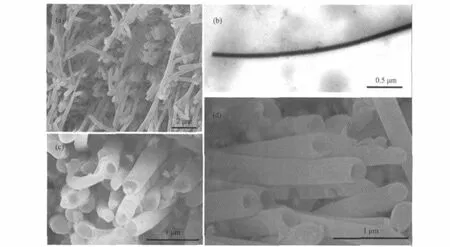
Fig.4 SEM and TEM images of Ni nanowire and nanotube arrays deposited at Ued=-0.5 V(a)top view of the Ni nanowires deposited from the solution with CNiSO4=0.05 mol·L-1,CEDTA=0.1 mol·L-1,CK2HPO4=20 g·L-1(sample 5),(b)typical TEM image of a piece of Ni nanowire in sample 5,(c)top view of the Ni nanowires deposited from the solution with CNiSO4=0.01 mol·L-1,CEDTA=0.02 mol·L-1,CK2HPO4=20 g·L-1(sample 6), (d)top view of the Ni nanotubes(nanowires)deposited from the solution with CNiSO4=0.001 mol·L-1,CEDTA=0.002 mol·L-1,CK2HPO4=20 g·L-1(sample 8)
When the concentration of the NiY2-ions is decreased to very low level in Fig.5(c,d)(such as 0.001 mol·L-1),the fabricated nanostructures indicated the opposite trends for nanotube and nanowire compared with those at higher NiY2-ion concentrations,thatisnanowiresat-1.5Vandnanotubesat-0.5V.Besides the Uedmentioned above,the effect of electromigration on the growth rates,Vwand Vb,should also be taken into account at lower diffusion rate.The electromigration of NiY2-ions to the counter electrode and concentration diffusion to the work electrodes can both increase the overpotential for the electrochemical deposition.The increased overpotential could lead to the decrease of the Vwand the Vb.The reduction rate of the Ni2+is relatively faster at more negative Ued(Fig.5(c),such as-1.5 V),while the lower diffusion rate of the NiY2-ions would largely reduce the deposition rate.So the similar growth rate of the wall and the bottom Vw≈Vbwould be obtained for the nanowire formation. We believe that the similar growth rates at middle level in cases of Fig.5(b,c)give rise to the similar results,which is originated from the balance between the potential effect and the concentration effect.At less negative Ued(-0.5 V),the reduction rate of Ni2+should be very low at lower concentration of the NiY2-ions.The less influence of the NiY2-electromigration and the very low reduction rate make the diffusion of the NiY2-ions sufficient enough.The Ni2+ions on the edge can be supplemented in time and adsorbed on the edge preferentially.As the result,the Vwis relatively higher than the Vb,which leads to the final nanotube formation.

Fig.5 Schematic diagrams of the growth processes of Ni nanotubes and nanowires at different electrodeposition conditions(a)and(b)are schematic diagrams of the growth processes of nanotubes at Ued=-1.5 V and nanowires at Ued=-0.5 V in the electrolytes with higher NiY2-concentrations, respectively,(c)and(d)are schematic diagrams of the growth processes of nanowires at Ued=-1.5 V and nanotubes at Ued=-0.5 V in the electrolytes with lower NiY2-concentrations,respectively.The dashed arrows represent the electromigration direction of NiY2-and their lengths show the different electromigration rates.The solid arrows represent the concentration diffusion direction of NiY2-.
Based on the above mentioned mechanism,Cu nanotube and nanowire arrays have also been fabricated at higher electrolyte concentration with more negative Ued(Fig.S2,which is available free of charge via the internet at http://www.whxb.pku.edu.cn). The nanowires can be obtained without the introduction of the chelating agent EDTA,while the nanotube arrays can be obtained with EDTA.The common mechanism for 1D nanostructure growth of Ni and Cu indicates that it could be a general strategy for growth of metal nanotubes and nanowires.The controlled preparation of Au(Fig.S3)and Co(Fig.S4)(which are available free of charge via the internet at http://www.whxb.pku.edu.cn) nanotube arrays at the similar electrodeposition conditions with the chelating agent(EDTA)confirms the possible application of this mechanism in fabrication of other 1D metal nanomaterials.
3 Conclusions
In summary,controlled synthesis of Ni nanotube and nanowire arrays can be obtained by electrodeposition using AAO template. Both nanotubes and nanowires can be readily achieved by varying the electrodeposition potential and the concentration of NiY2-.The detailed growth mechanism for metal nanotubes and nanowires was proposed based on systematic studies.The crucial contributing factors of the chelating agent,the electrodeposition potential,the concentration of the NiY2-,and the electromigration were all taken into account for clarification of the growth process.This method could be applicable to fabrication of other metal nanotubes and nanowires,which has high potetials for applications in nanocatalyses,chemical sensors,and nanoscale electronic and magnetic devices.
Acknowledgment: The authors would like to thank Dr.ZHONG Liang-Shu and Dr.LIANG Han-Pu at the Institute of Chemistry,Chinese Academy of Sciences for helpful discussion in electrodeposition experiments.
1 Iijima,S.Nature,1991,354:56
2 Li,Y.L.;Kinloch,A.;Windle,A.H.Science,2004,304:276
3 Wirtz,M.;Martin,C.R.Adv.Mater.,2003,15:455
4 Zhang,X.Y.;Zhang,L.D.;Lei,Y.;Zhao,L.X.;Mao,Y.Q. J.Mater.Chem.,2001,11:1732
5 Hong,B.H.;Bae,S.C.;Lee,C.W.;Jeong,S.;Kim,K.S.Science, 2001,294:348
6 Chen,J.;Tao,Z.;Li,S.Angew.Chem.Int.Edit.,2003,42:2147
7 Xu,D.S.;Xu,Y.J.;Chen,D.P.;Guo,G.L.;Gui,L.L.;Tang,Y. Q.Chem.Phys.Lett.,2000,325:340
8 Zhang,W.;Wen,X.;Yang,S.;Berta,Y.;Wang,Z.L.Adv.Mater., 2003,15:822
9 Yan,C.;Xue,D.Adv.Mater.,2008,20:1055
10 Huang,B.H.;Shen,P.Y.;Chen,S.Y.Nanoscale Res.Lett.,2009, 4:503
11 Xiao,R.;Cho II,S.;Liu,R.;Lee,S.B.J.Am.Chem.Soc.,2007, 129:4483
12 Lu,Q.;Gao,F.;Komarneni,S.;Mallouk,T.E.J.Am.Chem.Soc., 2004,126:8650
13 Matsumoto,F.;Nishio,K.;Masuda,H.Adv.Mater.,2004,16: 2105
14 Korgel,B.A.;Fitzmaurice,D.Adv.Mater.,1998,10:661
15 Wang,M.H.;Li,Y.J.;Xie,Z.X.;Liu,C.;Yeung,E.S.Mater. Chem.Phys.,2010,119:153
16 Gao,P.;Cai,Y.G.ACS Nano,2009,3:3475
17 Xiao,Z.L.;Han,C.Y.;Welp,U.;Wang,H.H.;Kwok,W.K.; Hiller,J.M.;Cook,R.E.;Miller,D.J.;Crabtree,G.W.Nano Lett., 2002,2:1293
18 Martin,C.R.Science,1994,266:1961
19 Gao,H.;Mu,C.;Wang,F.;Xu,D.S.;Wu,K.;Xie,Y.C.;Liu,S.; Wang,E.G.;Xu,J.;Yu,D.P.J.Appl.Phys.,2003,93:5602
20 Yoo,W.C.;Lee,J.K.Adv.Mater.,2004,16:1097
21 Wang,Y.;Wu,K.J.Am.Chem.Soc.,2005,127:9686
22 Qu,L.T.;Shi,G.Q.;Wu,X.F.;Fan,B.Adv.Mater.,2004,16: 1200
23 Yan,C.;Xue,D.Electrochem.Commun.,2007,9:1247
24 Wang,Y.;Lee,J.Y.;Zeng,H.C.Chem.Mater.,2005,17:3899
25 Franklin,N.;Dai,H.Adv.Mater.,2000,12:890
26 Routkevitch,D.;Bigioni,T.;Moskovits,M.;Xu,J.M.J.Phys. Chem.,1996,100:14037
27 Kamalakar,M.V.;Raychaudhuri,A.K.Adv.Mater.,2008,20:149
28 Wang,H.;Xu,C.W.;Cheng,F.L.;Jiang.S.P.Electrochem. Commun.,2007,9:1212
29 Liang,H.P.;Guo,Y.G.;Hu,J.S.;Zhu,C.F.;Wan,L.J.;Bai,C. L.Inorg.Chem.,2005,44:3013
30 Yang,L.X.;He,D.M.;Cai,Q.Y.J.Phys.Chem.C,2007,111: 8214
31 Han,C.H.;Hong,D.W.;Kima,I.J.;Gwak,J.;Han,S.D.;Singh, K.C.Sens.Actuators B,2007,128:320
32 Andzelm,J.;Govind,N.;Maiti,A.Chem.Phys.Lett.,2006,421:58
33 Sadrzadeh,A.;Farajian,A.A.;Yakobson,B.I.Appl.Phys.Lett., 2008,92:022103
34 Schider,G.;Krenn,J.R.;Gotschy,W.;Lamprecht,B.;Ditlbacher, H.;Leitner,A.;Aussenegg,F.R.J.Appl.Phys.,2001,90:3825
35 Lee,W.;Scholz,R.;Lee,N.K.W.;Scholz,R.;Nielsch,K.;Gosele, U.Angew.Chem.Int.Edit.,2005,44:6050
36 Bao,J.;Tie,C.;Xu,Z.;Zhou,Q.;Shen,D.;Ma,Q.Adv.Mater., 2001,13:1631
37 Levina,L.;Sukhovatkin,V.;Musikhin,S.;Cauchi,S.;Nisman,R.; Bazett-Jones,D.P.;Sargent,E.H.Adv.Mater.,2005,17:1854
38 Nanda,K.K.;Kruis,F.E.;Fissan,H.Nano Lett.,2001,1:605
39 Li,L.;Pan,S.S.;Dou,X.C.;Zhu,Y.G.;Huang,X.H.;Yang,Y. W.;Li,G.H.;Zhang,L.D.J.Phys.Chem.C,2007,111:7288
40 Zhang,X.Y.;Wang,H.T.;Bourgeois,L.;Pan,R.J.;Zhao,D.Y.; Webley,P.A.J.Mater.Chem.,2008,18:463
41 Fu,J.;Cherevko,S.;Chung,C.H.Electrochem.Commun.,2008, 10:514
42 Mu,C.;Yu,Y.X.;Wang,R.M.;Wu,K.;Xu,D.S.;Guo,G.L. Adv.Mater.,2004,16:1550
43 Huang,C.W.;Hao,Y.W.Nanotechnology,2009,20:445607
44 Liu,L.F.;Zhou,W.Y.;Xie,S.S.;Song,L.;Luo,S.D.;Liu,D.F.; Shen,J.;Zhang,Z.X.;Xiang,Y.J.;Ma,W.J.;Ren,Y.;Wang,C. Y.;Wang,G.J.Phys.Chem.C,2008,112:2256
45 Cao,H.Q.;Wang,L.D.;Qiu,Y.;Wu,Q.Z.;Wang,G.Z.;Zhang, L.;Liu,X.W.ChemPhysChem,2006,7:1500
46 Chowdhury,T.;Casey,D.P.;Rohan.J.F.Electrochem.Commun., 2009,11:1203
47 Lahav,M.;Sehayek,T.;Vaskevich,A.;Rubinstein,I.Angew. Chem.Int.Edit.,2003,42:5576
48 Liu,F.;Zhao,Z,J.;Qiu,L,M.;Zhao,L,Z.Anal.Test.Technol. Instrum.,2009,15:1