In、Sc掺杂对SrTiO3电子结构和光学性质的影响
2010-03-06江妮张志勇
江妮 张志勇
(西北大学信息科学与技术学院,西安 710127)
Strontium titanate(SrTiO3),a typical perovskite material,has attracted much attention due to its potential applications in the field of oxide devices[1-9].It can be used as a substrate for the growth of high temperature superconductor thin films[1],as grain boundary barrier layer capacitors[2]and oxygen gas sensors[3-4], and as a high permittivity material with potential application in dynamic random access memory[5].In particular,its conductivity can be tuned by controlled doping with impurity atoms[6-9],which has important applications in fabricating devices with multilayer structures such as semiconductor/insulator/semiconductor (S/I/S)and metal/insulator/metal(M/I/M)junctions[10].
The behavior of n-type doped SrTiO3has been widely studied in an attempt to understand the rich variations in physical properties arising from carrier doping[11-18].However,the achievement of p-type doped SrTiO3is rarely documented.Until now,only Sc-doped and In-doped SrTiO3are confirmed to be p-type doping[19-21].Higuchi et al.[19]reported the electronic structure of a ptype SrTiO3single crystal in which the acceptor ion Sc3+was introduced into the Ti4+site.Dai et al.[20]reported that SrTiO3exhibited p-type conductivity when doped by the substitution of In for Ti.Guo et al.[21]further explored the optical properties of ptype SrInxTi1-xO3(x=0.1 and 0.2)films prepared by laser molecular beam epitaxy under different oxygen pressures.In addition, many of the properties such as the structure stability,transport properties,and optical absorption spectra for p-type doped SrTiO3thin films are not known.
In this paper,we perform the first-principles calculation based on the density functional theory(DFT)[22]to investigate the effect of In and Sc p-type doping on the electronic structure and optical properties of SrTiO3.
1 Theoretical model and computational method
1.1 Theoretical model
SrTiO3has an ideal cubic perovskite-type structure at room temperature.It belongs to the space group Pm3m(Oh),with the Sr atom sitting at the origin point,Ti at the body centre,and three oxygen atoms at the three face centres,and its lattice constant is a=b=c=0.3905 nm.The unit cell contains one formula unit of SrTiO3.In order to study fractional substitution,it is necessary to consider a cell larger than the basic unit.Thus we construct a supercell of eight unit cells consisting of 40 atoms in the basis.Replacing any one of the Ti atoms by In(or Sc)atom in the supercell will correspond to the formula SrIn0.125Ti0.875O3(or SrSc0.125Ti0.875O3).
1.2 Computational method
In our computation,the interaction between nuclei and electrons is approximated with Vanderbilt ultra-soft pseudo-potential[23]treating 4s,4p,and 5s electrons of Sr,3s,3p,3d,and 4s electrons of Ti,2s and 2p electrons of O,4d,5s and 5p electrons of In,and 3s,3p,3d,and 4s electrons of Sc as the valence electrons.The Perdew and Wang 91 parametrization[24]is taken as the exchange-correlation potential in the generalized-gradient approximation(GGA).Plane wave basis with kinetic energy cutoff of 420 eV is used to represent wave functions.Brillouin zone integration is performed with a 6×6×6 Monkhorst-Pack[25]k-points mesh.Full relaxation is performed for the constructed supercells by using the Broyden-Fletcher-Goldfarb-Shanno(BFGS)algorithm[26]to minimize energy respect to atomic position.Each calculation is considered converged when the maximum root-meansquare convergent tolerance is less than 5.0×10⁻⁶eV·atom-1,that is,the maximum ionic Hellmann-Feynman force being within 0.1 eV·nm-1,the maximum ionic displacement being within 5.0×10⁻⁵nm and the maximum stress being within 0.02 GPa. Then the electronic structure and optical properties are calculated based on the optimized supercell model.
The scissor approximation is adopted in the optical calculation to compensate the underestimation of the calculated band gap.
2 Results and discussion
2.1 Stability and lattice properties
The binding intensity and structural stability of crystal are related to its binding energy.The bigger the binding energy,the more stable the crystal structure.In this paper,the binding energies for SrTiO3,SrIn0.125Ti0.875O3,and SrSc0.125Ti0.875O3are calculated by the following formulas[27]:

where Etotal(SrTiO3)and Etotal(SrM0.125Ti0.875O3)represent the total energies of the SrTiO3and SrM0.125Ti0.875O4supercells,respectively.Eisolate(X)denotes the total energy of an isolated X atom and n is the formula number of SrTiO3contained in each supercell.
By analysis of the calculated binding energies of the three compounds listed in Table1,we conclude that the optimized SrTiO3,SrIn0.125Ti0.875O3,and SrSc0.125Ti0.875O3systems are stable, because their binding energies are negative.On the other hand, the doped SrIn0.125Ti0.875O3and SrSc0.125Ti0.875O3have bigger binding energy values than the undoped SrTiO3itself,which indicates that the structure stability of SrTiO3is weakened after doping.These structure stability changes for SrIn0.125Ti0.875O3and SrSc0.125Ti0.875O3are originated from the electronic structure changes through doping,and we will discuss this in the Mulliken population analysis section.Note that the crystal structures of SrIn0.125Ti0.875O3and SrSc0.125Ti0.875O3are still the cubic perovskite-type structure with the space group Pm3m(Oh).
In addition,the calculated lattice constants are 0.3951 nm for SrIn0.125Ti0.875O3,larger than that of undoped SrTiO3(0.3924 nm), which is in good agreement with the experiment results[20]that thelattice constants of SrIn0.1Ti0.9O3films increase after doping. The same lattice expansion tendency is also observed in SrSc0.125Ti0.875O3.However,because of the absence of experimental result on the lattice parameters of SrSc0.125Ti0.875O3,further experimental work is needed for comparison with our numerical results.

Table 1 Optimized structure parameters and binding energies(Eb)for SrTiO3,SrIn0.125Ti0.875O3,and SrSc0.125Ti0.875O3
Further insight into the effect of p-type doping on the electronic structure of SrTiO3can be obtained from the atomic relaxation around the impurity atom as listed in Table 2.The partial geometries around the impurity In atom,which are taken from the structural optimized SrIn0.125Ti0.875O3system,are shown in Fig.1.
The introducing of In impurity leads to a local lattice expansion in the SrIn0.125Ti0.875O3.The closest atoms with respect to the In impurity are six O*atoms which rearrange their positions immediately after the doping has occurred.That is,the six nearest O*atoms around In atom shift away from In by 0.0025 nm and the InO6*octahedron exhibits a small structure relaxation.This is due to the fact that the effective radius of In3+(0.094 nm)is larger than the radius of Ti4+(0.0745 nm)[20],the partial substitution of In for Ti induces a structure relaxation.The same tendency is also observed for SrSc0.125Ti0.875O3after doping.However,the six nearest O*atoms around Sc atom move away from Sc by 0.0083 nm,much larger than that in SrIn0.125Ti0.875O3.Furthermore,in the case of the first nearest neighbor(NN)Ti*O6with respect to the InO6*octahedron in SrIn0.125Ti0.875O3,it possesses a slightly distorted Ti*O6octahedron.The bond length of Ti*—Oaalong the aaxis is smaller than those in the bc plane.So does the first NN Ti*O6with respect to the ScO6octahedron in SrSc0.125Ti0.875O3.At the same time,it is noted that the second NN Ti**O6undergoes little relaxations after doping and the third NN Ti#O6has almost no change in both SrIn0.125Ti0.875O3and SrSc0.125Ti0.875O3systems compared with the corresponding one in the undoped SrTiO3system.Hence,replacing a Ti atom by one In atom(or Sc atom) in the SrTiO3parent merely results in local structural changes around the dopant sites.

Fig.1 Partial geometry of the structural optimized SrIn0.125Ti0.875O3system
2.2 Electronic structures
In this part,the electronic structures of SrTiO3,SrIn0.125Ti0.875O3, and SrSc0.125Ti0.875O3will be discussed and compared with each other.Three indicators will be used to reveal the effect of In and Sc doping on the electronic structure of SrTiO3,which are the total density of state(DOS),partial density of state(PDOS),and population analysis.Each of these tools can demonstrate some aspects of structure features.
2.2.1 DOS
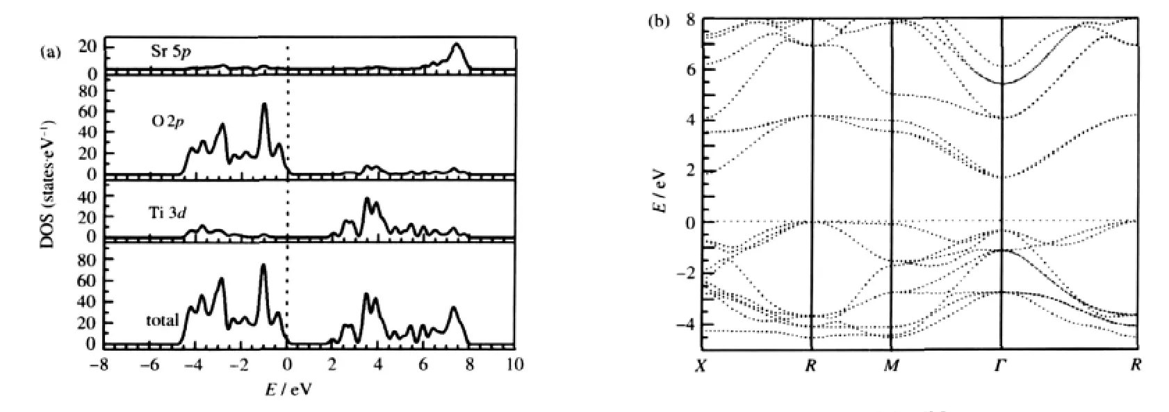
The DOS and PDOS of the undoped SrTiO3are calculated first for comparison and the results are shown in Fig.2(a).For the sake of clarity,only the relevant Ti 3d,O 2p,and Sr 5p PDOS are shown and this will be adopted in the subsequent figures.It is obvious that the structure of SrTiO3has corner-shared TiO6octahedron where the Ti 3d and O 2p interaction is found,which dominate the main electronic properties of SrTiO3.The top of valance bands(VBs)predominately consists of O 2p states and the most prominent unoccupied energy bands in the bottom most of conduction bands(CBs)are mainly composed of the Ti 3d states.Overlooking from the DOS,it can be observed that there is strong orbital hybridization between the Ti 3d and O 2p states. That is to say,Ti—O bond is covalent.Correspondingly no over-lap of PDOS between Sr atoms and O atoms means the high ionicity of Sr—O bonds.

Table 2 Key bond lengths in SrTiO3,SrIn0.125Ti0.875O3,and SrSc0.125Ti0.875O3

Fig.2 DOS and PDOSs(a)and band structure(b)of undoped SrTiO3The Fermi level is set to zero on the energy scale,which will be adopted below unless otherwise stated.
Moreover,as shown in Fig.2(b),the undoped SrTiO3is an indirect gap insulator with the top of valence band at R point and the bottom of conduction band at Γ point.The calculated value of the indirect band gap at R→Γ is 1.7 eV,which is smaller than the experimental value of about 3.2 eV[28].This is typically underestimated by the density functional theory[29-30].Thus,a scissor approximation value of 1.5 eV is adopted in the optical calculation to compensate the underestimation of the calculated band gap.
Fig.3showsthetotalDOSsofSrIn0.125Ti0.875O3andSrSc0.125Ti0.875O3. Because the In doping introduces the p-type carriers into the SrIn0.125Ti0.875O3system,the Fermi level shifts into the valence bands(VBs),which is in agreement well with the experimental results[20]that In3+acts as acceptor ions in the Indoped SrTiO3films and the SrIn0.1Ti0.9O3is a p-type semiconductor.Particularly,the DOS of SrIn0.125Ti0.875O3shifts significantly towards high energies and the optical band gap is broadened by about 0.35 eV due to In doping compared with the DOS reported in Fig.2.This is well consistent with the experimental results[20]that the band gap of SrIn0.1Ti0.9O3is 0.4 eV larger than that of undoped SrTiO3.Moreover,one additional peak with a bandwidth of about 1.20 eV appears in the bottom of VBs for SrIn0.125Ti0.875O3.
In the case of Sc-doped SrSc0.125Ti0.875O3,the Fermi level shifts downwards into the VBs and SrSc0.125Ti0.875O3exhibits p-type degenerate semiconductor feature,which agree well the experimental results[31]that Sc3+acts as acceptor ions in SrTi1-xScxO3and the Fermi level shifts to the VBs side with increasing Sc3+ions. Meanwhile,an optical band gap widening of 0.30 eV associated with Sc doping has been observed for SrSc0.125Ti0.875O3.This fact is consistent with the experimental results that the band gap of SrTi1-xScxO3increases with increasing Sc doping concentration[32]. The broadened optical band gap originates from two aspects.On the one hand,the Burstein-Moss shift due to the high concentration of carriers makes the optical absorption edge shifts towards high energies and the optical transparency window is broadened[33].On the other hand,interactions among hole charges result in a many-body effect,which causes the optical band gap to becomenarrow[34].However,theeffect of Burstein-Moss on the band gap is more pronounced than that of the many-body effect,so the band gap broadens after doping.
2.2.2 PDOS
In subsequent discussions on the effect of p-type doping on the SrTiO3system,we restrict ourselves to the PDOS of the doped systems.
Firstly,the orbital decomposed PDOSs of impurity In atom in SrIn0.125Ti0.875O3and Sc atom in SrSc0.125Ti0.875O3are presented in Fig.4(a).It is clear that the PDOSs of In and Sc do not contribute to the bottom most of CBs but contribute only to the top of VBs. The value of PDOS for In near the Fermi level(marked by the arrow in Fig.4(a))in the energy rang of-0.50 to 0.00 eV is significantly larger than that of Sc atom in SrSc0.125Ti0.875O3.This indicates that In is probably better than Sc for p-type doping in SrTiO3.
Secondly,the orbital decomposed PDOSs of atoms near the In and Sc impurities are plotted in Fig.4(b)and(c),respectively.In the case of SrIn0.125Ti0.875O3,it is found that there is strong interaction between impurity In and its first NN Ti*O6.The PDOS of Ti*3d states at the bottom of CBs is highly dispersive and shows no localization characteristics.With increasing distance between In and its neighboring TiO6,the PDOS of Ti**3d states is less dispersive than that of Ti*.The PDOS of Ti#atom is almost the same as that in undoped SrTiO3.Besides,the In impurity charge potential has great effect on the six O*atoms in the InO6.The PDOS of O*2p states at the bottom of CBs is different from that of other O atoms,which are not in the InO6.The same results are observed in SrSc0.125Ti0.875O3.These conclusions for SrIn0.125Ti0.875O3and SrSc0.125Ti0.875O3are in good agreement with the structure relaxation analysis in section 2.1 that the partial substitution of In for Ti(or Sc for Ti)in the SrTiO3parent merely results in local structural changes around the dopant sites.Moreover,by analysis the PDOS in Fig.4(a,b),it is evident that an additional peak appears in the bottom of VBs for SrIn0.125Ti0.875O3,to which the In 5s and O 2p states make contribution.

Fig.3 DOSs of SrIn0.125Ti0.875O3(a)and SrSc0.125Ti0.875O3(b)

Fig.4 PDOSs of impurity In atom in SrIn0.125Ti0.875O3and Sc atom in SrSc0.125Ti0.875O3(a),surrounding atoms of In(b)and neighboring atoms of Sc(c)
2.2.3 Mulliken population analysis
More investigation of the effect of In and Sc doping on the electronic structure of SrTiO3can be obtained from Mulliken population analysis listed in Table 3.For undoped SrTiO3,the net charge of Sr(1.87e)is close to its+2e formal charges,whereas O atom is with-0.80e negative charges and Ti atom carries 0.53e positive charges,which are much smaller than their-2e and+4e formal charges,respectively.This indicates that there is a high degree of covalency in the Ti—O bond while ionicity in the Sr—O bond,which agrees well with the DOS analysis for SrTiO3in section 2.2.1.
After doping,there are considerable electron charge density redistributionsneartheimpurityatom.InthecaseofSrIn0.125Ti0.875O3, the electron density of the O*atoms near the impurity In atom increases obviously and the electronegativity of O*atoms is strengthened.While the net charges of Ti*and Ti**decrease to the values of 0.50e and 0.52e,respectively.This is due to the fact that the net charge of In atom(1.26e)is much larger than that of the replaced Ti atom(0.53e),and In atom transfers more electrons to O*atoms.Correspondingly,Ti*and Ti**provide less electrons to O*atoms.Hence there is a high degree of ionicity in the In—O bond and the covalency of Ti—O bond is weakened after doping,which result in the structure stability change of SrIn0.125Ti0.875O3.For SrSc0.125Ti0.875O3,the impurity Sc atom loses only partial valence electrons with 0.46e positive charges,smaller than the replaced Ti atom(0.53e),implying that the covalent Sc—O bond is weaker than that of Ti—O bond.Correspondingly, Ti*and Ti**atoms transfer more electrons to O*atoms and the net charges of Ti*and Ti**increase to the values of 0.56e and 0.54e,respectively.
2.3 Optical properties
Next we discuss the effect of In and Sc doping on the optical properties of SrTiO3.The linear response of a system due to an external electromagnetic field with a small wave vector can be described with the complex dielectric function ε(ω)=ε1(ω)+ iε2(ω).The imaginary part of the dielectric function ε2(ω)is calculated from the momentum matrix elements between the occupied and unoccupied wave functions[35]as follows:

where ħω is the energy of the incident photon,V is the unit cell volume,p is the momentum operator,|kn>is a crystal wavefunction,and f(kn)is the Fermi distribution function.The real part of the dielectric function ε1(ω)is evaluated from the imaginary part ε2(ω)by the Kramers-Kronig relationship.

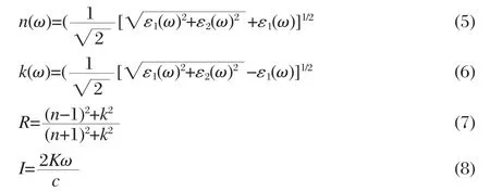
where M is the principal value of the integral.The other optical constants like refractive index n(ω),extinction coefficient k(ω), reflectivity R(ω),and absorption coefficient I(ω)now immediately are calculated in terms of the components of the complex dielectric function as follows:

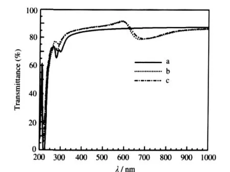
Accordingly the transmittance T(ω)can be obtained by the following equation:

Fig.5 shows the absorption spectra for SrTiO3,SrIn0.125Ti0.875O3, and SrSc0.125Ti0.875O3.After doping,a noticeable blue-shift of ab-sorption spectra edge is observed for SrIn0.125Ti0.875O3and SrSc0.125Ti0.875O3,which is in good agreement with the above calculated optical band gap widening for them.In addition,because of the Drude-type behavior of the free-carrier excitation[12],a new weak absorption appears in the energy region of 1.25 to 2.00 eV for the two p-type doping systems.

Table 3 Mulliken population analysis for SrTiO3, SrIn0.125Ti0.875O3,and SrSc0.125Ti0.87O3

Fig.5 Absorption spectra of SrTiO3(a),SrIn0.125Ti0.875O3(b), and SrSc0.125Ti0.875O3(c)
At the same time,as shown in Fig.6,the optical transmittance of SrIn0.125Ti0.875O3has a significant improvement after In doping and the transmittance is higher than 85%in a wavelength range from 350 to 625 nm,which agree well with the experimental results[21]thatSrIn0.1Ti0.9O3thinfilmsarehighlytransparentwiththe transmittance higher than 80%in most of the visible spectrum. For SrSc0.125Ti0.875O3,its optical transmittance is similar to that of SrIn0.125Ti0.875O3.
The increasing of the high transparency of the two p-type doping compounds originates from two factors.On one hand,to being optically transparent,it is desirable to have a wider band gap than the photon energy of the visible lights.Owing to the ptype doping,there is an optical band gap widening of 0.35 and 0.30 eV for SrIn0.125Ti0.875O3and SrSc0.125Ti0.875O3,respectively. Therefore,the electron transition occurring above 3.55 eV in SrIn0.125Ti0.875O3(3.50 eV in SrSc0.125Ti0.875O3)should be more beneficial than the band gap of 3.20 eV[28]in SrTiO3.On the other hand, the PDOS of impurity atom is low in the Fermi level(see Fig.4 (a)),which leads to the small transition probability and weak absorption.

Fig.6 Optical transmittances of SrTiO3(a),SrIn0.125Ti0.875O3(b),and SrSc0.125Ti0.875O3(c)
3 Conclusions
In conclusion,we have investigated the structure stability, electronic structure,and optical properties of In and Sc p-type doped SrTiO3by the first-principles calculation of plane wave ultra-soft pseudo-potential based on the DFT.Our calculation results are in good agreement with the experimental data.From these calculations,we have obtained the results as follows.
(1)The structures of SrIn0.125Ti0.875O3and SrSc0.125Ti0.875O3are still stable after doping,but their stabilities are lower than that of undoped SrTiO3.The partial substitution of In for Ti(or Sc for Ti) in the SrTiO3parent merely results in local structural changes around the dopant sites.
(2)Owing to the p-type doping,the Fermi level shifts into VBs for both SrIn0.125Ti0.875O3and SrSc0.125Ti0.875O3systems and the two systems display p-type degenerate semiconductor features. At the same time,the optical band gap of SrIn0.125Ti0.875O3is broadened by about 0.35 eV due to In doping and an optical band gap widening of 0.30 eV associated with Sc doping has been observed for SrSc0.125Ti0.875O3.
(3)A noticeable blue-shift of absorption spectra edge is observed for SrIn0.125Ti0.875O3and SrSc0.125Ti0.875O3and a new absorption appears in the energy region of 1.25 to 2.00 eV for the two p-type doping systems.Furthermore,the optical transmittances of SrIn0.125Ti0.875O3and SrSc0.125Ti0.875O3have a significant improvement after doping,and the transmittances are higher than 85%in the wavelength range from 350 to 625 nm. The wide band gap,small transition probability,and weak absorption due to the PDOS of impurity in the Fermi level result in the significant optical transparency.
1 Eom,C.B.;Marshall,A.F.;Laderman,S.S.;Jacowitz,R.D.; Geballe,T.H.Science,1990,249:1549
2 Shen,H.;Song,Y.;Gu,H.;Wang,P.;Xi,Y.Mater.Lett.,2002, 56:802
3 Hara,T.;Ishiguro,T.Sens.Actuator B-Chem.,2009,136:489
4 Hara,T.;Ishiguro,T.;Wakiyab,N.;Shinozakic,K.Mater.Sci. Eng.B,2009,161:142
5 Lee,S.W.;Kwon,O.S.;Han,J.H.;Hwang,C.S.Appl.Phys.Lett., 2008,92:222903
6 Fix,T.;Bali,R.;Stelmashenko,N.;Blamire,M.G.Solid State Commun.,2008,146:428
7 Zhu,X.B.;Liu,S.M.;Hao,H.R.;Li,X.H.;Song,W.H.;Sun,Y. P.Physica C,2005,418:59
8 Higuchi,T.;Tsukamoto,T.;Kobayashi,K.;Ishiwata,Y.;Fujisawa, M.;Yokoya,T.;Yamaguchi,S.;Shin,S.Phys.Rev.B,2000,61: 12860
9 Marina,O.A.;Canfield,N.L.;Stevenson,J.W.Solid State Ionics, 2002,149:21
10 Wang,H.H.,Chen,F.;Dai,S.Y.;Zhao,T.;Lu,H.B.;Cui,D.F.; Zhou,Y.L.;Chen,Z.H.;Yang,G.Z.Appl.Phys.Lett.,2001,78: 1676
11 Wang,H.H.;Cui,D.F.;Dai,S.Y.;Lu,H.B.;Zhou,Y.L.;Chen, Z.H.;Yang,G.Z.J.Appl.Phys.,2001,90:4664
12 Higuchi,T.;Tsukamoto,T.;Taguchi,Y.;Tokur,Y.;Shin,S. Physica B,2004,351:310
13 Ma,J.Y.;Bi,C.Z.;Fang,X.;Zhao,H.Y.;Kamran,M.;Qiu,X.G. Physica C,2007,463-465:107
14 Takizawa,M.;Maekawa,K.;Wadati,H.;Yoshida,T.;Fujimori,A.; Kumigashira,H.;Oshima,M.Phys.Rev.B,2009,79:113103
15 Blennow,P.;Hagen,A.;Hansen,K.K.;Wallenberg,L.R.; Mogensen,M.Solid State Ionics,2008,179:2047
16 Page,K.;Kolodiazhnyi,T.;Proffen,T.;Cheetham,A.K.;Seshadri, R.Phys.Rev.Lett.,2008,101:205502
17 Guo,X.G.;Chen,X.S.;Sun,Y.L.;Sun,L.Z.;Zhou,X.H.;Lu, W.Phys.Lett.A,2003,317:501
18 Evarestov,R.A.;Piskunov,S.;Kotomin,E.A.;Borstel,G.Phys. Rev.B,2003,67:064101
19 Hihuchi,T.;Tsukamoto,T.;Sata,N.;Ishigame,M.;Tezuka,Y.; Shin,S.Phys.Rev.B,1998,57:6978
20 Dai,S.;Lu,H.;Chen,F.;Chen,Z.;Ren,Z.Y.;Ng,D.H.L.Appl. Phys.Lett.,2002,80:3545
21 Guo,H.;Liu,L.;Fei,Y.;Xiang,W.;Lu,H.;Dai,S.;Zhou,Y.; Chen,Z.J.Appl.Phys.,2003,94:4558
22 Hohenberg,P.;Kohn,W.Phys.Rev.B,1964,136:864
23 Vanderbilt,D.Phys.Rev.B,1990,41:7892
24 Perdew,J.P.;Chevary,J.A.;Vosko,S.H.;Jackson,K.A.; Pederson,M.R.;Singh,D.J.;Fiolhais,C.Phys.Rev.B,1992,46: 6671
25 Monkhorst,H.J.;Pack,J.D.Phys.Rev.B,1976,13:5188
26 Pfrommer,B.G.;Cote,M.;Louie,S.G.;Cohen,M.L.J.Comput. Phys.,1997,131:233
27 Xiao,B.;Feng,J.;Zhou,C.T.;Xing,J.D.;Xie,X.J.;Chen,Y.H. Chem.Phys.Lett.,2008,459:129
28 Van Benthem,K.;Elsassser,C.;French,R.H.J.Appl.Phys.,2001, 90:6156
29 Sham,L.J.;Schluter,M.Phys.Rev.Lett.,1983,51:1888
30 Zhang,F.C.;Zhang,Z.Y.;Zhang,W.H.;Yan,J.F.;Yun,J.N. Acta Phys.-Chim.Sin.,2009,25:61 [张富春,张志勇,张威虎,闫军锋,贠江妮.物理化学学报,2009,25:61]
31 Higuchi,T.;Tsukamoto,T.;Yamaguchi,S.;Kobayashi,K.;Sata, N.;Ishigame,M.;Shin,S.Nucl.Instrum.Methods Phys.Res.Sect. B-Beam Interact.Mater.Atoms,2003,199:255
32 Higuchi,T.;Tsukamoto,T.;Sata,N.;Ishigame,M.;Kobayashi,K.; Yamaguchi,S.;Shin,S.Solid State Ionics,2002,154-155:735
33 Burstein,E.Phys.Rev.,1954,93:632
34 Mahan,G.D.J.Appl.Phys.,1980,51:2634
35 Saha,S.;Sinha,T.P.;Mookerjee,A.Phys.Rev.B,2000,62:8828
