Simulation of Droplet-gas Flow in the Effervescent Atomization Spray with an Impinging Plate*
2009-05-14QIANLijuan钱丽娟LINJianzhong林建忠andXIONGHongbing熊红兵
QIAN Lijuan (钱丽娟), LIN Jianzhong (林建忠),2,** and XIONG Hongbing (熊红兵)
Simulation of Droplet-gas Flow in the Effervescent Atomization Spray with an Impinging Plate*
QIAN Lijuan (钱丽娟)1, LIN Jianzhong (林建忠)1,2,** and XIONG Hongbing (熊红兵)1
1Department of Mechanics, State Key Laboratory of Fluid Power Transmission and Control, Zhejiang University, Hangzhou 310027, China2China Jiliang University, Hangzhou 310018, China
A comprehensive three-dimensional model of droplet-gas flow was presented to study the evolution of spray in the effervescent atomization spray with an impinging plate. For gas phase, the N-S equation with the-turbulence model was solved, considering two-way coupling interaction between droplets and gas phase. Dispersed droplet phase is modeled as Lagrangian entities, accounting for the physics of droplet generation from primary and secondary breakup, droplet collision and coalescence, droplet momentum and heat transfer. The mean size and statistical distribution of atomized droplets at various nozzle-to-plate distances were calculated. Some simulation results were compared well with experimental data. The results show that the existence of the impinging plate has a pronounced influence on the droplet mean size, size distribution and the droplet spatial distribution. The air-to-liquid ratio has obvious effects on the droplet size and distribution.
effervescent atomization spray, impinging plate, droplet distribution, Sauter mean diameter, simulation
1 INTRODUCTION
An air-assisted spray impinging normally on a surface is very common in the chemical industry. A better understanding in the influence of gas flow pattern on the droplet size and its distribution will help in designing spray systems to improve the performance. There is abundant literature discussing the prediction of a representative drop diameter in a spray [1], but there are few publications discussing the drop size distribution in sprays [2]. The research on droplet size and its distribution near the impinging plate for effervescent atomization has not yet been reported in the literature, although the prediction of drop size distribution near the impinging plate is critical to the plastering techniques. For modeling of drop size distribution, two analytical approaches have been developed in the past two decades,.., the maximum entropy (ME) pioneered by Sellens and Brzustowski [3] and Li and Tankin [4], and the discrete probability function (DPF) first applied in Newtonian sprays by Sovani[5]. In the DPF approach it is assumed that spray formation involves a series of breakup stages which include the primary atomization closed to the nozzle and the secondary atomization downstream along the spray.
The effervescent atomization is a form of internal- mixing twin-fluid atomization in which an atomizing gas is bubbled into a liquid and the resulting two-phase mixture is discharged from the atomizer orifice. Atomizers that embody this concept are found to operate at much lower injection pressures but produce finer sprays than those by conventional single and twin fluid atomizers. The atomizing gas-to-liquid ratio needed for effervescent atomization is also significantly lower than that of other twin-fluid atomization. In addition, the mean drop size in effervescent atomization is relatively insensitive to liquid viscosity, which means that a single atomizer can handle a variety of liquid. Therefore, effervescent atomization has been widely used in combustion, spray deposition and powder formation [6].
A comprehensive three-dimensional model which includes the breakup of annular sheet in the primary atomization as well as the breakup collision and coalescence in the secondary atomization is presented in this paper to examine the effervescent atomization spray evolution downstream of the exit orifice. The atomizing gas jet and the droplet trajectory are described in a three-dimensional domain. Both of the gas flow field and the droplet mean size have been validated with the published experimental data. Then the model is used to analyze the droplet size and distribution near the impinging plate under different nozzle- to-plate distances. The droplet mean diameter, size distribution and the spatial distribution are all taken into consideration for the purpose of finding a proper nozzle-to-plate distance, with which the finer and uniform droplets near the plate can be obtained.
2 MATHEMATICAL MODELS
Figure 1 (a) shows the inner structure of a typical steady-state effervescent atomizer, which consists of four main components: liquid and gas supply ports, a mixing chamber where the gas is bubbled into the liquid stream, and an exit orifice. Liquid is supplied to the atomizer axially and flows inside a perforated central tube to the exit orifice. The atomizing gas enters at the pressure slightly higher than the liquid and bubbles through the perforated tube into the liquid stream. The two-phase bubbly is then ejected through the exit orifice [6]. There are four possible flow regimes in the discharge orifice of an effervescent atomizer, including small bubble flow, larger bubble flow, slug flow and annular flow. As shown by the experiments of Sovani. [6] and Liu [7], annular flow pattern is beneficial for obtaining finer droplets [as shown in Fig. 1 (b)]. When two-phase mixture is discharged from the atomizer orifice, the rapidly expanding gas phase will shatter the liquid into finer droplets. Since these droplets is unstable in the turbulent spray, they undergo a series of events such as collision, breakup and coalescence, and finally the droplets entrained in the gas jet will impinge on the plate.

Figure 1 Schematic of effervescent atomization spray impinging on a planar plate
2.1 Gas phase modeling

The gas flow is turbulent, and the conservation equations for the mass, momentum and energy for the gas are written in terms of vectors and tensors as follows,


wherecellis the cell volume,pis the number of the droplets of this parcel, andpis the force acting on each droplet,pis heat flux at each droplet surface, andpis the particle velocity.
2.2 Droplet phase modeling
The dispersed droplet phase is modeled using Langrangian method, considering droplet tracking, heating transfer, primary and secondary breakup, collision and coalescence.
There are two sub-models used to describe the external flow of the particles. One is one-dimensional sub-model of droplet primary breakup, the other is the three-dimensional sub-model of droplet secondary breakup.
2.2.1
Based on the experimental results [7] of the flow near nozzle, the ligaments formed can be approximated by cylindrical jets. Three sub-processes occur during primary breakup. Firstly, the annular liquid sheath breaks into a number of cylindrical ligaments. Secondly, the ligaments break into ligament fragments. Finally, the ligament fragments are stabilized to form drops.
Estimation of annular liquid sheet thickness It is assumed that the annular two-phase flow within the discharge orifice is one-dimensional, inviscid and isothermal with compressible ideal gas and small interfacevelocity slip ratio. The momentum equation of the annular flow can then be written as the Bernoulli equation:


whereis the experimental coefficient, which is close to 1. The interface velocity slip ratio and void fraction are related by

Droplet mean size from primary breakup After obtaining the thickness of annular liquid sheet, we need to compute the length of a typical ligament fragment,.., the wavelengthat which the disturbance grows most rapidly. A solution provided by Senecal. [9] is used to estimate the growth rate of surface distributions,, for the sinusoidal mode:


Using this model, the initial droplet characteristics such as the initial value of32can be provided. More details and the validation of primary breakup model can be referred to Ref. [10].
2.2.2
The sub-model of droplet secondary breakup includes droplet tracking, heating transfer and evaporation, cascade atomization and drop breakup, and a droplet collision model. Among them, one of the most complex parts is the simulation of particle collision and breakup. There are two models most widely used in the simulation of droplet breakup. One is the Taylor analogy breakup (TAB) model by O’Rourke and Amsden [11] that is based on Taylor’s analogy between an oscillating droplet and a spring-mass system [12]. Over the years, many variations of this model have been developed, including the enhanced Taylor analogy breakup (ETAB) model by Tanner [13] and the cascade atomization and drop breakup (CAB) model [12]. The other droplet breakup model,.., the wave breakup model developed by Reitz [14] is widely used to simulate dense liquid sprays. For a dilute spray studied in the present work, the CAB model was used to describe droplet secondary breakup. On the hand of droplets collision model, Brazier-Smith. [15] proposed a binary collision model for water drops, which then developed and refined by Ashgriz and Poo [16]. In the present collision model, both permanent coalescence and bouncing have been taken into consideration.
Droplet tracking The liquid droplets are discretely treated in a Lagrangian manner. Computational droplets are generated at the points of injection and tracked throughout their flight. Assume that only drag force and gravity affect the droplet momentum transfer significantly for the droplet with size smaller than 100mm [17], the momentum transfer between the droplet and atomization jet can be described by


whereis the gravity force, and the coefficient of the drag forceDcan be expressed as

Droplet heating transfer and evaporation For the heat transfer between droplet and air jet, the heat conduction is neglected and the lumped analysis is used as follows:


Cascade atomization and droplet breakup modeling To model the droplet secondary breakup, a cascade atomization and drop breakup model [12] has been utilized. The drop distortion is described by a forced, damped, harmonic oscillator in which the forcing term is given by the aerodynamic droplet/gas interaction, the damping is due to the liquid viscosity, and the restoring force is supplied by the surface tension.


whereis the density,is the viscosity,is the surface tension,is the relative drop-gas velocity, and the subscripts g anddenote the gas or liquid, respectively. Drop breakup occurs when the normalized drop distortion,(), exceeds the critical value of 1.
The creation of the product droplets is derived using elements from population dynamics,.., for each breakup event it is assumed that the number of product droplets is proportional to the number of critical parent drops, where the proportionality constant depends on the drop breakup regime. From this, we can define the rate of droplet creation, which, in conjunction with the mass conservation principle between parent and product droplets, leads to the basic cascade breakup law:


whereandare the radii of the parent and product drops, respectively, andbuis the breakup time,.., the time until the normalized deformation() in the solution of Eq. (19) exceeds the value of 1.
Droplet collision modeling The droplet collision and possible coalescence are modeled by a collision Weber number. Collisions between drops can result in bouncing, permanent coalescence, or coalescence followed by separation.


Figure 2 Schematic of droplet collision


3 COMPUTATIONAL ISSUES AND BOUNDARY CONDITIONS
3.1 Computational domain
Figure 3 shows the computational mesh with the size of 56 (radial)×65 (axial)×32 (azimuthal) in the cylindrical coordinate system. Finer meshes are used for the core region of the spray. No effort has been made to validate the gird dependency since it is well established in the literature [17, 18]. The radius and axial lengths of the computational regime are 6 cm and 15 cm, respectively, and 2π in the circular direction. This computational domain corresponds to the experimental conditions of Ref. [19], where the impinging plate existed and to Ref. [20], although there was no impinging wall in the domain.
3.2 oundary conditions of gas phase


Figure 3 Geometry and computational mesh
3.3 Computational code
The computational code used in this study is developed upon the frame of LAVA-P-3D code [17]. The two-dimensional LAVA code was firstly utilized in the State University of New York at Stony Brook for the simulation of the plasma spray jet [22], and a three-dimensional version, named LAVA-P-3D, was later developed by Xiong. incorporating the effects of carrier gas and multiple particles injection [17]. A new program based on the LAVA-P-3D code was then developed at Zhejiang Univiersity of China for the simulation of effervescent atomization [10]. In this program, the gas phase is calculated based upon the LAVA-P-3D code. For the droplet phase, which significantly differs from the plasma spray, the primary atomization and the secondary breakup are both taken into consideration using two sub-models as described in the previous section on the mathematical model. This study considered the effects of the impinging plate on the effervescent atomization spray, which is very important to the accurate prediction of the droplet distribution and characteristics upon impact.
3.4 Initial condition of droplet parcels in secondary breakup

4 RESULTS AND DISCUSSION
4.1 Validations of computational model and code


□ experiments; —— simulations
Second, the droplets mean size along axial direction which is one of the most concerned atomization parameters has been validated using the published experimental data [20]. The structure of atomizer in both experiment and simulation are as the same as Fig. 3 indicated except for abandonment of the impinging plate. Both of them are taken under the same operating conditions of atomized liquid: water; air-to-liquid mass ratio: 0.067; nozzle radius: 0.2 cm; pressure inside the nozzle: 0.6 MPa, liquid flow rate: 90 kg·h-1; temperature: 300 K.

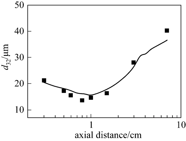
Figure 5 Droplet Sauter mean diameter of atomization spray along axial direction
■ experiments; —— simulations

Table 1 Basic operating conditions (atomized liquid: water)
These comparisons validate the present model and computational code, and they are used in the following sections to predict the behavior of the atomization in the domain with an impinging plate.
4.2 Effects of the impinging plate on d32 and droplets distribution
The prediction of droplet size and distribution is important in the applications. A better understanding in the influence of spray pattern on the droplet size and its distribution is in favor of designing the spray systems. Figs. 6-12 depict the comparisons of the atomization effect between the cases with and without impinging plate on different axial cross sections. The basic computational conditions are listed in Table 1. The structure and main size of the atomizer is as the same as Fig. 3 shows.
Figure 6 compares the streamline maps with the plate and without the plate. With the plate, a vortex is formed when the jet develops enough and closer enough to the plate, but vortex doesn’t occur in the flow field without the impinging plate. This change of the gas flow field will have an important impact on the spatial distribution of particles, particle mean size and size uniformity.
Figure 6 Comparison of the streamlines of the flow field with and without the plate
Figure 7 is the comparison of droplet number distributions at cross section plane with and without the plate at axial distance of 100 mm in the basic operating conditions. The center of droplets located area is slightly below of the nozzle axis due to the gravity effect in Fig. 7. The existence of the plate changes the gas flow pattern, which will bring the droplets travel to the side of the flow field and make the spatial distribution of droplet more uniform and broad.
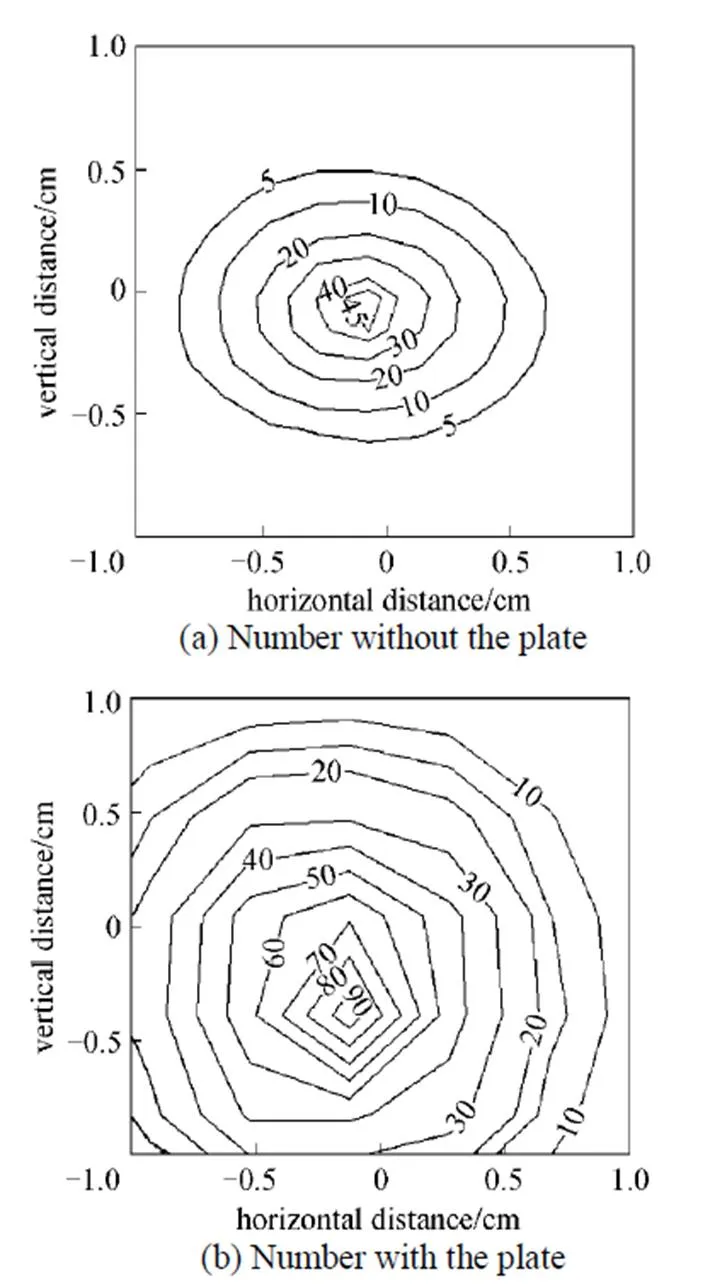
Figure 7 Comparison of droplet number distributions at cross section plane with and without the plate
Figure 8 shows the droplet spatial distribution at different axial distance of 15.6, 50, 100, 125 mm for the cases with and without the plate. It can be seen that the existence of the plate can promote the uniformity of droplet spatial distribution in some extent This phenomena is more obvious when the plate is located closer to the nozzle because the aerodynamic force is more intensive near the spray exit and this effect is more profound.
Two circular areas have been defined to describe the dispersion and width of droplet spatial distribution. One is named the total circle that takes the intersections of spray centerline and axial cross-section as the center of circle and includes 99% of droplets. The other is named central circle that takes the same center of circle as former and includes 85% of droplets. The radius of total circles and central circles at different axial distances are listed in Table 2. It can be seen that the distribution of droplet location becomes wider with the increase of the axial distance. The existence of the plate can spread the width of droplet distribution significantly.

Figure 8 Statistics for droplet spatial distributions at different axial distance of 15.6, 50, 100, 125 mm

Table 2 Radius of droplet spatial distributed area at different axial distances
Figure 9 is the comparison of droplet number distributions at cross section plane with and without the plate at axial distance of 100 mm in the basic operating conditions. It is obvious that the droplet size is more uniform for the case with the plate than that without the plate. At the cross section, large particles have more chance to appear in the center for the case without the plate than that with the plate.
In order to estimate the uniformity of droplet size, a dimensionless parameter is proposed to denote the mean square deviation:


Figure 9 Comparison of droplet size distributions at cross section plane with and without the plate
As Fig. 10 shows, when the axial distance within 100 mm, the mean square deviation fluctuates due to droplet breakup and collision, and the existence of the plate is of benefit to uniformity of the droplet size. When beyond 100 mm, the mean square deviation with the plate ascends over that without the plate, due to the attenuation of gas entrainment effect and the increase of the impact of the turbulent vortex structure on droplet coalescence, which will aggravate the droplet size differentiation.

Figure 10 Mean square deviation of droplet size at different axial positions
□ without plate;▲ with plate
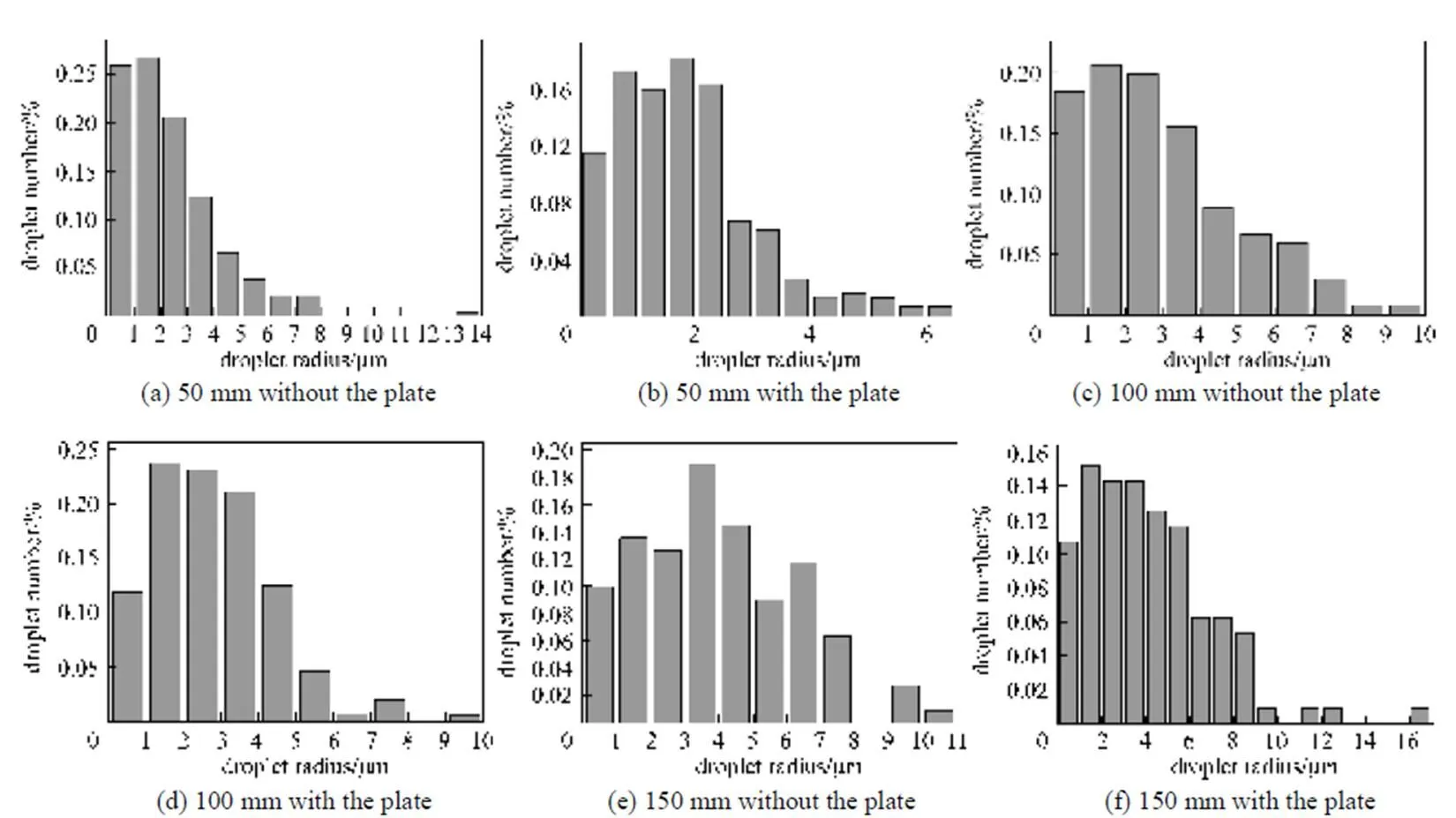
Figure 11 Statistical distributions of drop diameter at different axial distances of 50,100,150 mm
Figure 11 shows the statistical distributions of drop diameter at different axial distances of 50, 100, 150 mm. It can be seen that particle size distribution becomes more uniform and the distribution range is narrower in the cases with a plate at the place with axial distances of 50 and 100 mm. The situation is contrary when the plate is at the place with axial distance of 150 mm. It can be further explained as that with the weakening aerodynamic effect, the gas entrainment on the droplet trace decays and the impact of the turbulent vortex structure of impinging spray on the droplets intensifies, which can accelerate the collision and coalescence of the droplets.
As can be seen from Fig. 12, both the cases with and without the plate show that the droplet diameter increases with the axial distance at the downstream of the spray where the collision and coalescence would dominate due to a small velocity difference between drop and atomization gas as well as larger drop densities, making the diameter gradually increasing. While there is also an obviously influence of impinging plate on SMD32. When the plate is at the place within an axial distance from the nozzle of 100 mm, the SMD of the droplets in the region close to the plate is smaller than that without the plate, due to the intense influence of gas entrainment. On the other hand, when the plate is at the distance of 125 and 150 mm from the nozzle, the situation turns contrary, as the influence of gas entrainment on the droplet trace decays and the impact of the turbulent vortex structure of impinging spray on the droplets intensifies, which will accelerate the collision and coalescence of the droplets and evidently increase the droplet mean size. From the above analysis, it seems that the SMD will be finer in the spray field with a plate that located within 100 mm from the nozzle exit.

Figure 12 Droplet Sauter mean diameter at different axial positions
□ without plate;▲ with plate
Some factors have been taken as the indices for the appropriate position of the impinging plate,.., (1) smaller droplet mean size, smaller droplet size scattering, (2) uniformity of droplet spatial distribution, (3) efficiency of spray. As discussed above, the position of the plate at 15.6 mm from the nozzle meets (1) and (2) but fails in (3) because short distance from nozzle to plate will result in a huge splash and narrow region of droplet distribution. In the contrast, when the distance is longer than 100 mm, the droplet mean size becomes large and does not meet (1). Therefore, an appropriate position of the impinging plate should be 50-100 mm under the conditions given in this paper.
4.3 Effects of operating and initial conditions
In practical applications, various operating and initial conditions can be used to adjust the atomization effect. Fig. 13 shows the droplet Sauter mean diameter (SMD) under different gas-to-liquid mass ratios (AL). The plate is at the place with axial distance of 100 mm from the nozzle and all the operating parameters are as same as that in Table 1 except the air flow rate is varied as 180, 280, 380 L·min-1to get differentAL. Evidently, the droplet SMD gradually decreases with an increasing inAL. The reason is that larger gas flow rate enhances the droplet distortion and breakup. Besides, as shown in Fig. 14, the drop distribution becomes more scattered and the probability of drop collision and coalescence decrease for the cases with more gas flux or less liquid flux, which makes the droplet mean diameter become small. Fig. 14 also shows that the droplet distribution is more uniform and the range of the droplet distribution is wider asALincreases because the enhancement of the initial gas flow rate makes more droplets scatter to the rim, which can improve the atomized effect.

Figure 13 Droplet Sauter mean diameter along axial direction under different gas-to-liquid velocities
AL: □ 0.139;● 0.216;△ 0.294

Figure 14 Statistics for droplet spatial distributions at axial distance of 100 mm
Figure 15 shows the effect of initial droplet radius and nozzle size on the droplet SMD. The operating parameters are as same as that in Table 1 except the air flow rate is 6333 cm3·s-1. The plate is at the place with axial distance of 100 mm from the nozzle. It can be seen that the nozzle size and initial droplet radius have great effects on the initial atomized droplet size. Smaller initial droplet radius and nozzle size will lead smaller droplet mean diameter. In the region downstream, the effect of the nozzle size and initial droplet radius becomes weak and droplet SMD become consistent. This phenomenon meets the characteristics of effervescent atomization.

Figure 15 Droplet Sauter mean diameter along axial direction
5 CONCLUSIONS
A comprehensive three-dimensional model of droplet-gas two-phase flow is presented to study the evolution of spray in the effervescent atomization spray with an impinging plate. The results show that the existence of the impinging plate has a pronounced influence on the droplet mean size, size distribution and the droplet spatial distribution. Various distances from the nozzle to impingement plate have been taken into consideration in the computation. An appropriate position of the impinging plate should be 50-100 mm from the nozzle under the conditions given in this paper. The effects of air-to-liquid ratio, initial droplet radius, and nozzle size on the droplet atomization are discussed. The air-to-liquid ratio affects the droplet size and distribution obviously. The atomized effect can be improved by increasing the air-to-liquid ratio. Initial droplet radius and nozzle size impact the droplet size in the region upstream, while the effects become weak and droplet Sauter mean diameter becomes consistent in the region downstream.
NOMENCLATURE
Ddrag coefficient
cspecific heat, J·kg-1·K-1
cconstant volume specific heat
nozzle diameter, cm
32Sauter mean diameter, μm
internal energy, J
force, N
gravity force, N
distance between nozzle exit and impinging plate, cm
pressure, Pa
heat flux, W·m-2
gas constant of air, J·K-1
ALair-to-liquid mass ratio
radius, cm
sinterface velocity slip ratio
temperature, K
relative drop-gas velocity, cm·s-1
0gas velocity at nozzle exit, cm·s-1
,,velocity component, cm·s-1
volume
radial coordinate, cm
axial coordinate, cm
volume fraction of gas
deformation parameter
dynamic viscosity, g·cm-1·s-1
density, g·cm-3
surface tension, N·m-1
drop oscillation frequency, s-1
Superscripts
— mean
Subscripts
ccell
conv convective
cr criteria
g gas
liquid
o orifice
p particle
s sheet
v vaporization
1 Devi, P.S., Lee, Y., Margolis, J., Parise, J.B., Sampath, S., Herman, H., Hanson, J.C., “Comparison of citrate-nitrate combustion and precursor plasma spray processes for the synthesis of yttrium aluminum garnet”,..., 17 (11), 2846-2851 (2002).
2 Babinsky, E., Sojla, P.E., “Modeling drop size distributions”,..., 28, 303-329 (2002).
3 Sellens, R.W., Brzustowski, T.A., “A prediction of the drop size distribution in a spray from first principles”,., 1 (2), 89-102 (1985).
4 Li, X., Tankin, R.S., “Droplet size distribution: a derivation of a Nuliyama-Tanasawa type distribution function”,..., 6, 65-76 (1987).
5 Sovani, S.D., Sojka, P.E., Sivathanu, Y.R., “Prediction of drop size distributions from first principles: the influence of fluctuations in relative velocity and liquid physical properties”,., 9, 113-152 (1999).
6 Sovani, S.D., Sojka, P.E., Lefebvre, A.H., “Effervescent atomization”,..., 27, 483-521 (2001).
7 Liu, L.S., “Experimental and theoretical investigation on the characteristics and two-phase spray flow field of effervescent atomizers”, Ph.D. Thesis, Tianjing University, China (2001). (in Chinese)
8 Ishii, M., “One dimensional drift-flux mode and constitutive equations for relative motion between phases in various two-phase flow regimes”, Argonne National Laboratory Report, 77-47 (1977).
9 Senecal, P.K., Schmidt, D.P., Nouar, I., Rutland, C.J., Reitz, R.D., Corradini, M.L., “Modeling high speed viscous liquid sheet atomization”,.., 25, 1073-1097 (1999).
10 Xiong, H.B., Lin, J.Z., Zhu, Z.F., “Three-dimensional simulation of effervescent atomization spray”,., 19 (1), 1-16 (2009).
11 O’Rourke, P.J., Amsden, A.A., “The TAB method for numerical calculation of spray droplet breakup”, SAE Paper, 872089 (1987).
12 Tanner, F.X., “Development and validation of a cascade atomization and drop breakup model for high-velocity dense sprays”,., 14, 211-242 (2004).
13 Tanner, F.X., “Liquid jet atomization and droplet breakup modeling of nonevaporating diesel fuel sprays”,.., 106 (3), 127-140 (1998).
14 Reitz, R.D., “Modeling atomization processes in high-pressure vaporizing sprays”,., 3, 309-337 (1987).
15 Brazier-Smith, P.R., Jennings, S.G., Lantham, J., “The interactions of falling water drops: coalescence”,...., 326, 393-407 (1972).
16 Ashgriz, N., Poo, J.Y., “Coalescence and separation in binary collisions of liquid drops”,.., 221, 183-204 (1990).
17 Xiong, H.B., Zheng, L.L., Sampath, S., Williamson, R.L., Fincke, J.R., “Three-dimensional simulation of plasma spray: effects of carrier gas flow and particle injection on plasma jet and entrained particle behavior”,.., 47, 5189-5200 (2004).
18 Xiong, H., Zheng, L.L., Sampath, S., Fincke, J., Williamson, R., “Three-dimensional simulation of plasma spray jet”,.., 3, 689-697 (2003).
19 Baydar, E., Ozmen, Y., “An experimental and numerical investigation on a confined impinging air jet at high Reynolds numbers”,..., 25, 409-421 (2005).
20 Liu, L.S., Fu, M.L., Wu, J.X., “The distribution of SMD downstream the discharge orifices of effervescent atomizers”,..., 22, 653-656 (2001). (in Chinese)
21 Yu, Y., Zhou, L.X., Wang, B.G., “Modeling of fluid turbulence modification using two-time-scale dissipation models and accounting for the particle wake effect”,...., 14 (3), 314-320 (2006).
22 Wan, Y.P., Pasad, V., Wang, G.X., Sampath, S., Fincke, J.R., “Model and powder particle heating, melting, resolidification, and evaporation in plasma spraying procsees”,., 121, 691-699 (1999).
23 Rosin, P., Rammler, E., “The laws governing the fineness of powdered coal”,.., 7, 29-36 (1933).
2008-01-13,
2008-10-28.
the Major Program of the National Natural Science Foundation of China (10632070).
** To whom correspondence should be addressed. E-mail: mecjzlin@public.zju.edu.cn
杂志排行

Chinese Journal of Chemical Engineering的其它文章
- Modeling and Optimization for Scheduling of Chemical Batch Processes*
- Numerical Investigation of Constructal Distributors with Different Configurations*
- The Kinetics of the Esterification of Free Fatty Acids in Waste Cooking Oil Using Fe2(SO4)3/C Catalyst
- Multiple Model Soft Sensor Based on Affinity Propagation, Gaussian Process and Bayesian Committee Machine*
- Measurement and Correlation of Solid-Liquid Equilibria of Phenyl Salicylate with C4 Alcohols
- Steam Reforming of Dimethyl Ether over Coupled Catalysts of CuO-ZnO-Al2O3-ZrO2 and Solid-acid Catalyst*