Evaluation of Dielectric Properties of CCTO-BT/Epoxy Composites for Electronic Applications
2024-03-12SwagatikaMishraPunyapriyaMishraPunyatoyaMishraDineshMishra
Swagatika Mishra, Punyapriya Mishra*, Punyatoya Mishra, Dinesh Mishra,
(1.Department of Mechanical Engineering, Veer Surendra Sai University of Technology, Burla, Odisha 768018, India;2. Department of Physics, Parala Maharaja Engineering College, Berhampur, Odisha 761003, India;3. Department of Metallurgical and Materials Engineering, Veer Surendra Sai University of Technology, Burla,Odisha, 768018, India;4. Department of Chemical Engineering,Veer Surendra Sai University of Technology, Burla, Odisha 768018, India)
Abstract:In the current study, the calcium copper titanate (CCTO)/epoxy, barium titanate (BT)/epoxy and CCTO-BT/epoxy composite samples with variable volume fractions of CCTO and BT are fabricated using hand lay-up and compression moulding process.The composite samples are characterized for the frequency dependence on dielectric properties, conductivity, impedance spectroscopy and electrical modulus.X-ray diffraction (XRD) representation of CCTO-BT/epoxy composite samples confirmed the presence of both CCTO and BT ceramic samples separately.The dielectric characteristics of hybrid CCTO-BT/epoxy composite samples with CCTO∶BT ratio of 40∶60, 60∶40, and 50∶50 was found relatively better than those of single ceramic filler reinforced epoxy composites.AC conductivity analysis shows improvement in the results of hybrid filler-filled CCTO-BT/epoxy composites in comparison with single filler-filled epoxy composite.50∶50 CCTO-BT/epoxy composite shows the best AC conductivity value of ~2.2×10⁻⁵ ohm-1·m-1 at a higher frequency of 1 MHz.The impedance analysis confirms the higher insulating properties for hybrid 40∶60 and 60∶40 CCTO-BT/epoxy composites with respect to the single and other hybrid ceramic epoxy composites.The analysis suggests the hybrid CCTO-BT/epoxy composites to be adopted as a potential dielectric material for energy storage devices and other electronic applications.
Keywords:ceramic filler; dielectric characterization; hybrid Composite; AC conductivity; impedance analysis
0 Introduction
The explosive demand for high performance, light weight, and low-cost electronic communication devices encourages miniaturization of these devices from discrete to the embedded one[1].A capacitor is the most vital part of an electronic device as it stores the energy under the electric field.Further, the embedded capacitors implanted in thin laminates form a multilayer printed circuit board (PCB) to function as a parallel plate capacitor in both power and ground planes.It minimizes the requirement of surface mount capacitors and solders joints to free of space and save cost with increase in the reliability, speed, and electrical performance of the PCB as compared to the discrete capacitor[1-2].Dielectric materials show a leading role in the miniaturization of these devices, hence integration and packaging techniques are highly essential.These integration and packaging techniques usually demand a low dielectric loss with moderate dielectric constant, good flexibility and low cost[3-8].
In current years, polymer ceramic materials incorporated with lead-free ferroelectric ceramics are recognized to be an exceptional material for insulators and dielectrics; since it combines the good properties of ceramics and polymers while eradicating the bad one.Both dielectrics of high and low dielectric constants are crucial in electronic industries.Generally, ceramics display higher dielectric constant along with low dielectric breakdown field which are brittle in nature.However, polymers are well known for their flexibility, easy and low-temperature processing, and higher dielectric breakdown field[9- 10].This is worth noting that, incorporation of these two materials in one composite is considered as an ideal material for dielectric insulators for capacitors[11-14].Some insulating polymers like polyethylene, polyimide, silicone, and epoxy resins are widely used in electronic products due to their greater electrical performance with low-temperature processability with additional materials[15-16].The epoxy-based materials are magnificent dielectric materials with excellent mechanical strength, high dielectric properties, thermal stability, and good chemical resistance.The most frequently used ceramic materials are lead based ferroelectrics like PZT (Lead Zirconate Titanate) and its derivatives.They are adopted widely as dielectric materials because of their higher dielectric constant, ferroelectric along with piezoelectric properties.But, considering the environmental issues, lead-free ceramics are coming into the picture and becoming a promising material for modern research[17-21].
Recently, numerous researchers have adopted hybrid composites for their enhanced properties.Saidina et al.[3]synthesized and characterized BT and CCTO hybrid filler reinforced epoxy thin-film composite samples for dielectric, thermal and mechanical properties.The study reported a positive hybrid effect towards thermal and dielectric properties of CCTO: BT composite, proving the suitability for electronics applications.Saidina et al.[5]evaluated the result of filler loading and filler types on dielectric, thermal, and tensile behaviour of CCTO-BT/epoxy hybrid thin composite film and observed a significant enhancement in the dielectric behaviour because of the hybrid effect.Vovchenko et al.[6]synthesized the multi-walled carbon nanotubes (MWCNT)-BT/epoxy hybrid composite andfound a notable improvement in the electrical conductivity and complex permittivity in the MWCNT-BT/epoxy hybrid composite.Owing to the different shapes, dispersion characteristics and aspect ratio of hybrid fillers, literatures confirmed the development in the characteristics and performance of the samples in contrast to single fillers[22-24].However, the frequency dependency on the electrical characterization of the hybrid filler composite material is still an area of interest which requires to be examined to conclude about the performance of the composite materials in electronic applications.
In this study, hybrid ceramic polymer composites were synthesized and characterized to analyze and compare the frequency dependence of electrical properties.X-ray diffraction (XRD) investigation was done to estimate the phase evolution of the composites.Further, experiments were done to evaluate the effect of frequency on conductivity, dielectric properties, impedance, and electrical modulus of single and hybrid filler reinforced epoxy composites.The SEM (Scanning Electron Microscope) and FTIR (Fourier Transform Infrared) analysis were executed to evaluate the structure-property co-relation.
1 Materials and Methods
1.1 Details of Materials Used
The CCTO ceramic was prepared using calcium carbonate (CaCO3, LOBA Chemie, 98% purity), copper oxide (CuO, LOBA Chemie, 98% purity), and titanium dioxide (TiO2, LOBA Chemie, 98% purity).For the preparation of BT ceramic samples, barium carbonate (BaCO3, LOBA Chemie, 98% purity) and titanium dioxide (TiO2, LOBA Chemie, 98% purity) were used.Bisphenol-A-diglycidyl-ether (LY 556) was used as epoxy resin procured from Sambalpur, Odisha, India.HY 951 (tri-ethylene-tetramine) was used as hardener supplied by Ciba-Geigy of India Ltd, India.
1.2 Preparation of Composite Samples
The composite samples were produced using traditional solid-state reaction route.The precursors were first heated in a digital oven at 110 ℃ for 1 h to eradicate the moisture content.The stoichiometric ratio of all precursors was mixed using an agate mortar pestle for 4-5 h.For proper homogeneous mixing of precursors in CCTO and BT ceramic samples, acetone and ethanol respectively were used as a grinding medium.The corresponding mixtures are then dried and calcined.The calcination temperature of CCTO and BT ceramic samples were 1000 ℃ for 12 h and 1200 ℃ for 6 h respectively.The calcined ceramic samples were ground in a mortar with a pestle for 3 h to make them in powder form.
The composite samples were prepared using powder of CCTO and BT ceramic as reinforcement in epoxy resin (bisphenol-A-diglycidyl-ether, LY 556) matrix and tri-ethylene-tetramine (HY 951) as a hardener.The specimen samples were fabricated at five different weight ratios of filler materials (powder of CCTO and BT) like 100∶0, 0∶100, 50∶50, 60∶40, 40∶60, where reinforcement to polymer ratio was 20∶80.Before starting the fabrication process, the required amount of epoxy resin was sonicated for half an hour to achieve a temperature of 60-70℃ that lowers the viscosity of the liquid.Calcined CCTO and BT ceramic powders were added to the sonicated mixture according to the required weight ratio.After mixing ceramic powders with epoxy matrix, the hardener was added to it.The mixture was properly mixed by stirring in a continuous manner for 10-15 min with a mechanical stirrer at room temperature.Afterward, the solution was poured inside a stainless-steel mould previously coated with silicone spray (as a mould releasing agent) with a dimension of 180 mm×180 mm×3 mm and was kept at room temperature for 24 h for post-curing at 120 ℃ for 2 h at a pressure of 70.32 kg/cm2in a compression moulding machine.Post curing, the samples were chilled to room temperature and were taken out of the mould to prepare various sizes as per the requirement for characterization.
1.3 Characterization of Composites
The crystallographic structure study of the samples was performed using Rigaku, Japan (Ultima-IV) XRD analyzer.The XRD designs of the composites having different compositions were verified by Rigaku diffractometer using CuKα radiation with a 2θvalue in the range 20°-80°and step size 0.02.Electrical properties measurement of composite samples was obtained by spreading silver paste over the composite samples.Further, the conductivity and dielectric characteristics were measured with the help of computer interfaced HIOKI 3532-50LCR-HITESTER.The morphological study of the composites was evaluated for the structure-property co-relation by using a (Model-SU3500; Hitachi, Japan) SEM.A thin layer of gold coating was applied on the fractured surfaces before taking of microstructural view to improve the sample’s conductivity.
2 Results and Discussion
2.1 Study of XRD
The XRD examination of CCTO ceramic powder, BT ceramic powder, and polymer ceramic composite samples are presented in Figs.1 and 2.The XRD micrographs of pure CCTO and BT ceramic powder (Fig.1) depicted several crystalline peaks at 2θvalues of 29.58°, 34.30°, 38.41°, 42.29°, 45.84°, 49.28°, 61.36°for CCTO and 22.26°, 28.45°, 38.93°, 45.40°, 56.31°, 65.80°for BT.This result visualized a good agreement with the micrograph of CCTO and BT as described by Almeida et al.[25]and Valim et al.[26].It confirms the evolution in single perovskite phase development without any involvement of the secondary phase.XRD micrograph with distinct and sharp peaks described its good crystallinity and homogeneity.
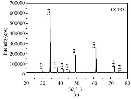
Fig.1 XRD micrograph of pure (a) CCTO and (b) BT powder
The XRD micrographs of CCTO/epoxy, BT/epoxy and CCTO-BT/epoxy composite samples are represented in Fig.2.The XRD representations for single ceramic reinforcement such as CCTO/epoxy and BT/epoxy composites exhibit several sharp peaks at approximate 2θvalues of 20.29°, 31.45°, 38.82°, 45.30°for BT/epoxy and 34.21°, 49.26°, 61.29°for CCTO/epoxy.The XRD micrographs of the CCTO-BT/epoxy hybrid composite show peaks at approximate 2θvalues of 20.29°, 31.45°, 34.21°, 38.82°, 45.30°.The detected peaks in XRD pattern resemble with the pure CCTO and BT peaks.The XRD pattern of CCTO-BT/epoxy composites shows the unique presence of both CCTO and BT ceramics.It can be observed from the figure that the peak intensity of XRD patterns varies according to the increase and decrease of CCTO and BT ceramic powder volume percentage.No traces of impurities were detected in any XRD micrographs.

Fig.2 XRD micrograph of BT/epoxy, CCTO/epoxy, 50∶50 CCTO/epoxy, 60∶40 CCTO/epoxy, 40∶60 CCTO-BT/epoxy composite samples
2.2 Dielectric Characterization
The study of dielectric characteristics is well-defined by two elementary electrical characteristics: capacitive insulating nature as the first one and the conduction nature as the second one[27].The capability of storing electrical charges is termed as capacitive insulating nature.On the other hand, the capability of transferring electric charge is referred to as conduction nature.Fig.3 illustrates the deviation in dielectric constant (ε′) of CCTO/epoxy, BT/epoxy, and CCTO-BT/epoxy composites with the variation in frequency at room temperature (30 ℃).The frequency range for dielectric properties measurement was taken in between 100 Hz-1 MHz.Comparing the dielectric constant values of single filler (CCTO or BT)-reinforced epoxy composite, the dielectric constant of CCTO/epoxy composite was obtained to be slightly more than BT/epoxy (Fig.3(a)).The obtained dielectric constant values are ~13.339 for CCTO/epoxy and ~8.957 for BT/epoxy composite at 100 Hz frequency.Further, the dielectric constants of CCTO/epoxy and BT/epoxy composites do not show much difference relative to CCTO and BT (105and 103).The prime reason for this may be the small dielectric constant value of epoxy polymer, which directly influences the dielectric property of polymer composites.A similar type of trend was also presented by Prakash et al.[28]in their studies on the difference between the dielectric characteristics of polymer ceramic materials.On the other hand, at 100 Hz frequency, the dielectric constants of hybrid filler-filled CCTO-BT/epoxy composites with CCTO to BT ratio of 40∶60, 50∶50, 60∶40 gives the higher constant value of ~11.04, 10.183, 11.357 respectively (Fig.3(b)) compared to epoxy (~4) and BT/epoxy composites while slightly lower than CCTO/epoxy composites.The 60∶40 CCTO-BT/epoxy composite has shown the highest dielectric constant among all hybrid composites at 100 Hz frequency.However, the 40∶60 CCTO-BT/epoxy composite is found to have the peak dielectric constant value of ~8.35 at 1 MHz frequency.It was detected that the dielectric constant was drastically reduced with the rise in frequency value for both single filler and hybrid filler epoxy matrix composites (Fig.3).The dielectric permittivity change is attributed mainly to dielectric polarization.At a higher frequency, dipolar polarization decreases, which means little time is needed to polarize the dipole moment of matrix and filler; and keep going on with the applied electric field[29].With higher frequency, the decreasing trend of dielectric constant value becomes constant, which corresponds to interfacial polarization and is renowned as the Maxwell-Wagner-Siller effect.The charge carriers’ displacement is accountable for the heterogeneity of the composite system that later on leads to interfacial polarization[30].
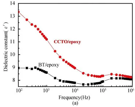
Fig.3 Dielectric constant versus frequency graph for (a) CCTO/epoxy and BT/epoxy (b) CCTO-BT/epoxy composites at room temperature (30 ℃)
The difference in dielectric loss(ε″) of both single and hybrid filler-filled epoxy composites at normal temperature (30 ℃) was shown in Fig.4.The obtained dielectric loss value for CCTO/epoxy composite (~3.1) was found relatively much higher than for BT/epoxy composite (~0.1) at 100 Hz (Fig.4(a)).Higher dielectric loss of CCTO/epoxy composite is describing the presence of CCTO ceramic filler in the epoxy matrix since CCTO ceramic powder exhibits higher dielectric loss in contrast to BT ceramic powder.On the other hand, at 100 Hz, the maximum dielectric loss values of CCTO-BT/epoxy hybrid composites were found as ~0.8, 1 and 0.15 for 60∶40, 40∶60, and 50∶50, respectively(Fig.4(b)), which attributes among the hybrid CCTO-BT/epoxy composites, 50∶50 CCTO-BT/epoxy hybrid composite has the lowest dielectric loss value.The dielectric loss of the composite samples shows a declining trend with an increase in frequency.This behavior may be due to the epoxy matrix relaxation[31].The epoxy matrix relaxation is principally affected by the interfacial polarization effect that leads to electric charge accumulation on every side of ceramic particles[32].Moreover, the decreasing trend of dielectric loss with frequency may be due to the ions’ migration inside the material at the low frequency region, conduction loss of ion migration and contribution of ion jumps and ion polarization at medium frequency region, and ion vibration at a high frequency region[33].
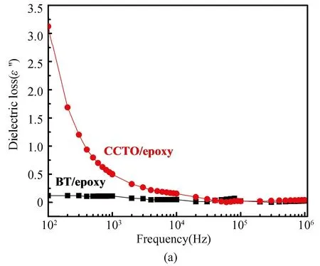
Fig.4 Dielectric loss versus frequency graph for (a) BT-Epoxy and CCTO-Epoxy (b) [(CCTO-BT)-Epoxy] at room temperature (30 ℃)
Further, it was observed that an overall increment in the volume percentage of CCTO in the composite increases the dielectric constant and loss values, while the rise in BT volume percentage decreases the corresponding values.So, the presence of BT in CCTO-BT/epoxy hybrid composite greatly improves the dielectric properties while reducing the dielectric loss values.Moreover, in contrast to single ceramic filler, hybrid ceramic fillers produce an optimistic effect on the dielectric performance of epoxy matrix-based samples due to their structural variation, and difference in span factor, and particle size[34].In the case of hybrid fillers, the size difference among the ceramic particles leads to improve packing efficiency of the composites that enhances the polarization to ameliorate the dielectric characteristics.The CCTO-BT/epoxy hybrid composite of higher dielectric constant along with less dielectric loss can be recommended for electronic storage device applications.
2.3 Conductivity Study
AC conductivity study was executed to analyze the conduction mechanism of the prepared composite samples with variable reinforcements.Fig.5 depicts the frequency response of AC conductivity (σa.c.) of CCTO/epoxy, BT/epoxy, and hybrid CCTO-BT/epoxy samples between 100 Hz-1 MHz frequency range at room temperature (30 ℃).AC conductivity of the samples can be calculated by using the equation[35]:
σa.c.=2πfε0ε′tan(δ)
(1)
wherefis the frequency,ε0is the permittivity of vacuum, and tan(δ) is the loss tangent.At low frequencies, all composites show a frequency-independent behavior whereas at higher frequencies, the composites show a frequency-dependent behavior.At room temperature, the AC conductivity value of the composite samples was showing a growing trend with the rise in frequency (Fig.5); this may be because of the amplification in the conduction mechanism[36].It is also evident that in contrast to the conductivity of CCTO/epoxy composites, BT/epoxy composites show stable conductivity values with varying frequencies.Hence, CCTO/epoxy may soon reach to dielectric breakdown stage with increasing frequency.But, BT-epoxy may not attain to dielectric breakdown stage as earlier as that of CCTO-epoxy because of its stable nature, which promotes the benefit of using hybrid composites in contrast to the individual one.It was also observed that the 50∶50 CCTO-BT/epoxy composite was found with the maximum AC conductivity value of ~(2.2×10⁻⁵) ohm-1·m-1at a high frequency of 1 MHz(Fig.5).

Fig.5 AC Conductivity (σa.c.) for BT/epoxy, CCTO/epoxy and CCTO-BT/epoxy composites at room temperature (30 ℃)
2.4 Impedance and Modulus Study
Fig.6 illustrates the real and imaginary components of impedance for CCTO/epoxy, BT/epoxy and CCTO-BT/epoxy composites on the applied field in the range of frequency from 100 Hz - 1 MHz at room temperature(30 ℃).It was detected from the study that the real as well as the imaginary impedance of both single and hybrid composites decreases with the rise in frequency.The cause may be due to the interfacial polarization at the low-frequency region, which causes charges to accumulate around the ceramic particles.It also represents the insulating nature of the material.At less-frequency region, the high impedance rate of the material indicates better insulation.40∶60 and 60∶40 CCTO-BT/epoxy composites have shown higher impedance values than single and other hybrid ceramic epoxy composites (Fig.6(a)), which attributes to their higher insulating nature.
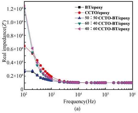
Fig.6 Impedance (frequency dependence) for BT/epoxy, CCTO/epoxy and CCTO-BT/epoxy composites at room temperature (30 ℃)
Fig.7 shows the real and imaginary sections of the electrical modulus for CCTO/epoxy, BT/epoxy, and CCTO-BT/epoxy composites at room temperature (30 ℃) with the varying frequency range from 100 Hz-1 MHz.The electrical modulus (M*) can be computed using the equation as follows[37]
(2)
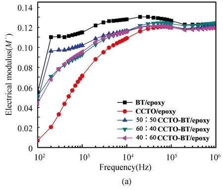
Fig.7 Variation in (a) real part and (b) imaginary part of electrical modulus(M*) for CCTO/epoxy, BT/epoxy, and CCTO-BT/epoxy composites with the variation in frequency at room temperature (30 ℃)
whereM′ andM″ are the real and imaginary parts of the electrical modulus, respectively.The calculated electric modulus values were used to analyze the frequency-dependent relaxation processes of single and hybrid ceramic epoxy composites.In the beginning, the calculatedM′ values show an increasing trend with frequency which further decreases and became constant (Fig.7(a)).
The obtained experimental data shows considerable dispersion at low temperature and frequency.Since the chosen room temperature(30 ℃) is less than the glass transition temperature (Tg) of the polymer matrix; hence it is tough to detect the relaxation behavior.The imaginary part of electric modulus (M″) peaks indicate a relaxation process not apparent in the dielectric loss value.These peak values represent α-relaxation of the relaxation process.It was also observed from the analyzed data that theM''value diminishes with rise in frequency and again increases with higher frequency (>100 kHz) which attributes to the rise in relative permittivity (ε′) of the composites as per the above Eq.(2).
2.5 SEM Analysis
Fig.8(a) and (b) represent SEM micrographs of BT/epoxy and CCTO/epoxy composites.Figure shows distribution of ceramic particles at a random manner in epoxy matrix.Fig.8 (c), (d) and (e) represent SEM micrographs of CCTO-BT/epoxy composite samples with variable volume fractions of 40-60, 50-50 and 60-40, respectively.The ceramic particles were distributed uniformly in epoxy matrix as observed from the figure.With rise in volume fraction of ceramics, the connectivity of samples increase which confirms 0-3 connectivity[38].
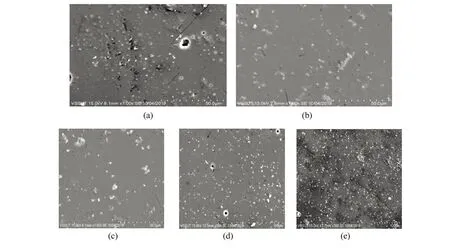
Fig.8 (a) SEM of BT/epoxy composite (b) CCTO/epoxy composite (c) 40-60, (d) 50-50 and (e) 60-40 composite
3 Conclusions
The conclusions drawn from the study are as follows:
1)The dielectric properties of hybrid CCTO-BT/epoxy composite are found relatively better than those of single ceramic filler reinforced epoxy composites such as CCTO/epoxy and BT/epoxy composites.The reinforcement of both BT and CCTO as hybrid filler form into the epoxy matrix improves the dielectric constant value while minimizing the dielectric loss.
2)The AC conductivity analysis confirms both BT and CCTO hybrid filler reinforcement in epoxy matrix-based composite significantly improves the conductive behavior of the individual ceramic (CCTO or BT) filler reinforced epoxy composite.Henceforth, 50∶50 CCTO-BT/epoxy composite has shown the maximum AC conductivity value of ~(2.2×10⁻⁵) ohm-1·m-1at a high frequency of 1 MHz.
3)Further, from impedance analysis, 40∶60 and 60∶40 CCTO-BT/epoxy composites are found to have higher insulating nature than the single and other hybrid ceramic epoxy composites.
4)The evaluation of the frequency dependence electrical properties for single and hybrid filler-filled epoxy composites confirms that the hybrid CCTO-BT/epoxy composites are proven to be an effective material for energy storage devices; and other electronic applications in contrast to single filler-filled CCTO/epoxy and BT/epoxy composite.
杂志排行
Journal of Harbin Institute of Technology(New Series)的其它文章
- Home-based Detection and Prediction of Diabetic Foot Ulcers at Early Stage Using Sensor Technology and Supervised Learning
- Erosion Wear Behaviour of Kenaf /Glass Hybrid Polymer Composites
- Intelligent Energy Utilization Analysis Using IUA-SMD Model Based Optimization Technique for Smart Metering Data
- Design of Fully Automatic Specification Selection System for Resistance Welding Equipment
- Juxtapose of System Performance for Food Calorie Estimation Using IoT and Web-based Indagation
- Comprehensive Overview and Analytical Study on Automatic Bird Repellent Laser System for Crop Protection
