Identification of time-varying system and energy-based optimization of adaptive control in seismically excited structure
2024-02-23ElhamAghabarariFereidounAminiandPedramGhaderi
Elham Aghabarari, Fereidoun Amini and Pedram Ghaderi
Department of Civil Engineering, Iran University of Science and Technology, Tehran 16844, Iran
Abstract: The combination of structural health monitoring and vibration control is of great importance to provide components of smart structures.While synthetic algorithms have been proposed, adaptive control that is compatible with changing conditions still needs to be used, and time-varying systems are required to be simultaneously estimated with the application of adaptive control.In this research, the identification of structural time-varying dynamic characteristics and optimized simple adaptive control are integrated.First, reduced variations of physical parameters are estimated online using the multiple forgetting factor recursive least squares (MFRLS) method.Then, the energy from the structural vibration is simultaneously specified to optimize the control force with the identified parameters to be operational.Optimization is also performed based on the probability density function of the energy under the seismic excitation at any time.Finally, the optimal control force is obtained by the simple adaptive control (SAC) algorithm and energy coefficient.A numerical example and benchmark structure are employed to investigate the efficiency of the proposed approach.The simulation results revealed the effectiveness of the integrated online identification and optimal adaptive control in systems.
Keywords: integrated online identification; time-varying systems; structural energy; multiple forgetting factor recursive least squares; optimal simple adaptive control algorithm
1 Introduction
Recently, the development of smart structures has been considered by researchers.Smart structures require a combination of system identification and control at the same time.Chenet al.(2010) and Huanget al.(2012) introduced the combination of building control and health monitoring in the domains of time and frequency, respectively.Since a time-varying system is clearly considered in smart structures, it is important to choose methods of system identification and control that are adapted to the needs of the time-varying system.Heet al.(2014), (2017); Amini and Aghabarari (2021)proposed the combination of vibration control and health monitoring; however, it can be employed for a time-invariant system.Yanget al.(2014) also examined the combination of health monitoring and control during an earthquake.However, the proposed methods have been offered as an offline combination.Leiet al.(2020a and 2020b) further suggested the generalized extended Kalman filter (GEKF) method and linear quadratic Gaussian (LQG) control.While in smart structures the use of online identification with optimal adaptive control that is compatible with changing conditions is required,the system identification and structural control methods of each have been extensively studied separately.In online identification, the virtual synchronization method(Ghaderi and Amini, 2020a and 2020b) and wavelet analysis (Basuet al., 2008) have been introduced.Adaptive identification with modal information has also been investigated (Amini and Ghasemi, 2018).Moreover, identification via the Kalman filter method has been performed (Suet al., 2018; Liet al., 2019).One of the most helpful methods of identification is the recursive least squares method (Jimenes-Febian and Alvarez-Icaza, 2008) improved by using the forgetting factor (Gonget al., 2014; Askariet al., 2016; Xiaet al.,2018) that confirms online parameter tracking (Vahidiet al., 2005; Liuet al., 2019).
Semi-active control systems have removed many of the challenges in the industry of structural control.Semiactive control is utilized by combining the reliability of passive methods and compatibility and adaptability of active methods.In addition, they do not require significant energy resources.
Throughout the last few decades, semi-active controllers with different algorithms (Pnevmatikos and Thomos, 2014; Pnevmatikos, 2017; Wanget al., 2019)have been proposed.One of the semi-active control algorithms, i.e., the simple adaptive control method(SAC), was introduced in 1998.Adaptive control has successfully been implemented in flight control systems and space structures.And simple adaptive control with high capability has been suggested by Kaufmanet al.and its stability has been discussed (Kaufmanet al., 1998;Barkana, 2013).This algorithm is used with acceleration feedback (Javanbakht and Amini, 2016) and backstepping control (Liet al., 2017; Ghaderi and Amini, 2018).It has also been utilized in asymmetric (Aminiet al., 2018),nonlinear (Bitaraf and Hurlebaus, 2013), and large space structures (Huet al., 2018).Based on the SAC algorithm,a method for damage detection is also suggested (Amini and Rabiepour, 2017).The control algorithms need to be cost-effective and enforceable; thus, they are optimized.Structural energy is investigated as an index of study and optimization in the structural control.The improvement of the linear quadratic regulator method (Alavinasabet al., 2006) and its use in three-dimensional structures has been examined by Yaniket al.(2014).Additionally, due to structural vibrations and the application of control force (Wong and Yang, 2001) in a 20-story benchmark model (Lynch and Law, 2004), the approaches have been taken into consideration using energy.Utilizing an energy-based algorithm has been introduced to control the structure (Minet al., 2003; Zelleke and Matsagar,2019).Therefore, one of the practical tools that can be used to optimize the structural control force in different algorithms is the calculation of structural energy at any time.
From the literature review, an approach combining the online identification and adaptive control simultaneously is needed.Thus, in this study, an integrated approach is proposed, in which the abrupt and gradual degradation in stiffness and damping parameters of each floor are identified while measurement noise is added to the seismic excitation.Furthermore, minimum information of sensors is recorded instead of full measurements of structural responses at all DOFs.The energy from the structural vibration and probability density function are calculated for each time.Optimal control command is captured using the SAC algorithm with the velocity feedback and switching scheme of the energy coefficient.Furthermore, the behavior and convergence of the proposed method is improved by embedding a first-order filter.The efficacy of the suggested approach is then investigated by utilizing a numerical study and comparing it with various cases.Finally, the performance of the proposed algorithm is evaluated by simulating the results.
In this study, an integrated approach for online estimation and optimal adaptive control is pursued.Section 2 states the problem and provides background of the proposed method for the structures under seismic excitation.Section 3 presents details of the methodology for system identification with the multiple forgetting factor recursive least square (MFRLS) and SAC algorithm while the control force is optimized by energy.In Section, the effectiveness of the proposed method is demonstrated using a numerical example and phase I IASC-ASCE benchmark building.Finally, Section 5 presents the conclusions of this work.
2 Problem formulation of the identified and controlled structure
The governing equation of motion for a structural system under seismic excitation is expressed as follows:
HerexH(t),x˙H(t)andx˙˙H(t)are the vectors of structural displacement, velocity, and acceleration responses, respectively.KeandCeare the identified stiffness and damping matrices.The mass matrixΜis known.f(t) andf*(t)denote the external excitation and optimal control force, respectively.Γis the influence matrices off*(t).At any time, the structure is subjected to seismic excitation.The structural parameter reduction is identified online, and the controller force is calculated according to the SAC algorithm with velocity feedback.The details are explained in the next section.The control force calculated from SACusacis optimized as follows:
in whichρrepresents the energy coefficient.The control force is passed through the first-order filter as:
The vibration energy of the structure is calculated at any time.The scheme of the switch for the coefficientρis determined by the designer in a way that if the structural energy is less than a certain value, the coefficientρwill be used between the values of zero to one; otherwise, the coefficientρis considered to be 1.
In the present study, the structural information is measured.In the identification block, the structural stiffness and damping elements are identified by the MFRLS method.At each time, the output of the system model is compared with the reference model to determine the controller tracking error.The value ofTandTare specified based on the purpose of the SAC algorithm, and the control command is computed by the SAC algorithm.The energy from the vibration of the structure is calculated simultaneously with the SAC algorithm.Finally, the control force optimized by the energy coefficient is passed through the first-order filter to improve the output.The proposed approach is conceptually shown in Fig.1.
3 Methodology
3.1 Stru€ctural parameters identification via MFRLS method
The recursive least square (RLS) method is a good strategy for tracking constant parameters (Vahidiet al.,2005; Askariet al., 2016; Liuet al., 2019).The linear regression model is expressed as follows:
Here at a generic time stepk,y(k) is the measurement vector of the ordern.φT(k) is the observation matrix with n×h dimension.The observation matrix includes the available values of the plant’s responses obtained from the measurements or analysis of the data.θˆ(k)is the unknown parameter vector of the plant withh×1 dimension.his the number of the unknown parameter of the plant, anndegree of freedom is for a structure withnstoriesν(k)is the noise disturbance.
In smart structures, the structural parameters of time and tracking variations are important.In the classical RLS method, the covariance matrix reaches zero as time progresses and loses its capability to keep track of changes in the parameters.
Therefore, the RLS method with forgetting factor is defined in real time, in which more weight is given to the recent data and less weight to the older data.
If the system parameter values change abruptly or gradually, it can potentially take on new values of the parameters.However, since the rate of variations of parameter estimation is different, it is necessary to adopt a different forgetting factor for each parameter.The forgetting factors are decoupled.In recent years, the improved RLS method with multiple forgetting factors has been employed in estimating time-varying systems.This method has been investigated as a constant or adaptive multiple forgetting factor in various fields of engineering (Vahidiet al., 2005; Askariet al., 2016; Liuet al., 2019).In this approach, the objective function is defined based on the error decomposition due to the different parameters in Eq.(6).The number of unknown parameters isn.
Hereλnis called the forgetting factor and is usually a number between 0 and 1.Estimationθˆn(k) is calculated by minimizing the objective function in the closed form solution as follows:
and
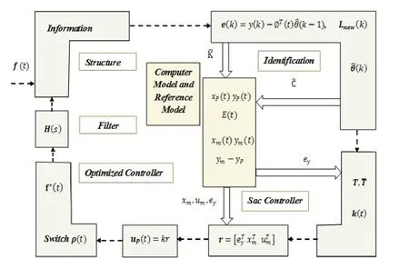
Fig.1 Schematic diagram of the proposed approach
HerePn(k) denotes the covariance matrix, andLn(k) is the gain matrix.
Eventually, the parameters are estimated with the gainLnew(k) matrix withh×kdimension as:
P(0) andθˆ (0) are the initial values of the covariance matrix and the estimation of unknown parameters,respectively, affecting the convergence rate.The initial estimate of the unknown parameters is considered to be zero.The estimateP(0) of the covariance matrix is described as:
α1in Eq.(13) is positive and has large values, andIis the identity matrix.
The parameters of the shear-type structure are moved and rearranged to take appropriate forms ofy(k) ,θˆ(k),andφT(k) matrices for the MFRLS method application.The governing equation of motion in a linear structural plant with degrees of freedom under seismic excitation is as follows:
Herex(t) ,x˙(t) andx˙˙(t) show the structural displacement, velocity, and acceleration, respectively.Μ,CandKare, respectively, the structural mass,damping and stiffness matrices withn×ndimensions.f(t) is the vector of the external excitation force.
in whichX˙˙g(t) is the ground acceleration, andgΛis the column vector of ones.
3.1.1 Minimal information of sensors
In this study, important factors, including the cost effectiveness of the number of measurement sensors and the defect of the sensors, are considered in the system health monitoring.Therefore, the number of measurement sensors in the implementation is detracted.In addition to the added noise, variations of physical parameters are identified via minimum information instead of full measurement of structural responses at all DOFs.Since there is no information of the displacement, velocity,and acceleration sensors on some floors, the responses are measured every other floor.Note that the changes of structural responses are the average of the adjacent floors.The error values of the control and displacement signal are calculated by the error(t) formula:
whereyˆ(t) shows the values with the estimated parameters, andy(t) shows the values with target parameters.
3.2 Simple adaptive control method
The reference model with an ideal behavior is defined in the SAC algorithm.The objective is to track the behavior of the reference model by the system.Hence, the output of the system is compared with the output of the reference model at any time.Then, system and model tracking errors are minimized by the control input.Equations in the form of the state space for a linear plant are:
HerePuism×1 plant control vector, andxPisnP×1 state vector.Pnis the plant’s order.PA,PB,CPandPDare the state, input, output matrices, and feed forward matrix, respectively.doanddiare the output and input disturbances, respectively.ypis the output vector of orderm.The governing equation of motion with the control force is converted to the state space form (Eqs.(22) and (23)).
in whichnis the degree of freedom of the structure, andris the number of control forces.
The system output is required to follow the output of the defined reference model.The ideal reference model is provided by the designer.The input command vector of the reference model could take a constant value or any variable and arbitrary value.The reference model is written as follows:
in whichmuism×1 input command vector,xmisnm×1 state vector, andnmis the order of the model.mA,mB,Cm, andDmare the state, input, output matrices, and feed forward matrix, respectively.ymis the output vector of the reference model.Note that thenmstate order of the model can be less than thePnorder of the plant.
One of the benefits of the SAC controller is the selection of a reference model with a lower order of the plant that is significant in the structures with a high degree of freedom or complexity.
The output tracking error of the algorithm is:
The control command vector is computed as:
and:
where
The adaptive gains containing proportionalkP(t)and integralkI(t) terms are described in Eqs.(29)and (30).In these equations,TandTare selected as positive definite scaling metrics.AsTincreases,kP(t)enhances.Therefore, the accuracy and speed of the algorithm are augmented, and theeyerror decreases.
It is assumed that close to the steady state of the system, the rate of thekI(t) change is almost zero;thus, if declines andTincreases for the specified value of the tracking error,kI(t) will also increase.At this point, the designer is obliged to take a balance between accepting a larger integral gain matrix or embracing a larger acceptable error (Kaufmanet al., 1998).Positive values of theσcoefficient are usually exploited to a number less than one to prevent the divergence of the integral gain.The stability of the SAC algorithm is justified based on the Lyapunov stability theory.To implement the asymptotic stability of the closed-loop of the algorithm in the multi-input multi output plant,satisfying the strictly positive real conditions is required in a way that the plant is in the minimum phase, the product ofCP×BPis determined by a positive definite symmetric matrix, and the value ofPDis zero (Barkana,2013; Javanbakht and Amini, 2016).
3.3 Optimization of the SAC control algorithm
The structural energy can be used as an index to obtain effective control force when controller force is optimized.In this study, the optimum control force is calculated by the energy coefficient of the structure at any time.The energy coefficient is computed simultaneously with the identified parameters, and the energy coefficient is related to the structural energy probability.It is assumed that the energy of the structure under excitation has a Rayleigh probability distribution of the structure.Based on the fact that the structural energy is always positive and the occurrence probability of minimum energy is zero (Minet al., 2003; Hwanget al., 2004);the Rayleigh probability density function is defined as:
HereEminis the minimum energy andσis the scale parameter.By placing the mean value in Eq.(31), the mean value of energy is defined as:
Then, the Rayleigh probability distribution of the structure is:
HereE(t) andE(t) are the current energy and mean energy of the structure, respectively.The energy due to the structural vibration included potential and kinetic energy at any time and it is computed as:
where
in whichxP(t) is the displacement and velocity vectors.Ke(t) andMare the structural identified stiffness and known mass, respectively.
The mean energy value is further obtained by computing the mean state of the system and placing it in the energy equation (Eq.(34)).
The operatorE[.] is the mean function, and the residual value is given as:
in whichγandnμcoefficients are regarded as less than one.HT(k) is the observation matrix withn×bdimension.
By partitioning, the system states can be divided into measured and unmeasured variables.Therefore,the structural energy of Eq.(34) can be expressed in the following terms:
HerexP1andxP2are the measured and unmeasured state variables, respectively.q11,q12,q21andq22are the elements ofQrelated to the measured and unmeasured variables.It is assumed that the measured states are exactly the same as the actual states and the unmeasured states are characterized by minimizing the structural energy in a way that the minimum ofxP2is obtained by calculating the energy derivation relative to the unmeasured variable and equal to zero (Eq.(44)).
Then,
The minimum energy is offered by placing the minimum unmeasured statexP2minin the energy equation:
The energy coefficient value1ρindicates the probability distribution of the structural energy, where the energy coefficient is changed between zero to one.The target energy valueEris defined in the energy probability distribution between the mean energy and the minimum energy.
Hereαis used to indicate the uncertainties and convergence.Theβcoefficient is chosen between values of -1 to 1.Theβandαminvalues are proposed by the designer based on the structural properties, control efficiency, and earthquake excitation (Minet al., 2003).Considering the switch scheme for the behavior of the structure, control force optimization is performed as:
HerecEis the value of the critical energy selected based on the various earthquakes entering the structure and the design of structures, as presented in Eq.(50):
Herein,E0-minis the minimum energy of the uncontrolled structure.When the structural minimum energy was less than the value of the critical energy, the energy coefficient is less than one; thus, the SAC control force is optimized.Otherwise, the energy coefficient is calculated to be one.Finally, the optimal control force is obtained using Eq.(3).
4 Numerical study
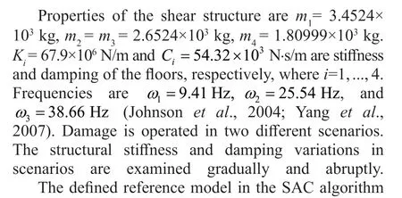
The efficiency and performance of the proposed approach in online identification of the plant parameters and optimal adaptive control are evaluated by the experimental example and benchmark structure.The structure is investigated under the El-Centro (1940)earthquake excitation with a time step of Δt=0.02 s based on the measured information.An online estimation of the stiffness parameter is implemented by the measured acceleration responses of each floor.The noise is also added to the seismic excitation.Moreover,the energy coefficient is simultaneously implemented with the identification at any time.The optimal control force is calculated through Eq.(1).Evaluation criteria are adopted for the optimization performance of the proposed method.
System stateXPcontains velocity and displacement vectors in the energy index due to structural vibrationJX.Other indices are:
TheJ1andJ2indicate the root mean square (RMS)of the displacement and absolute acceleration response,respectively.The RMS of the response time durationtfunder seismic excitation is calculated as:

4.1 3-DOF Plant simulation

3.3 × 10⁵N/m.To identify the stiffness parameters based on the formulas presented in this study, the covariance matrix and estimation of the parameters are initially considered.
Noise is added to the seismic input with intensity of RMS 5%.The forgetting factors are:

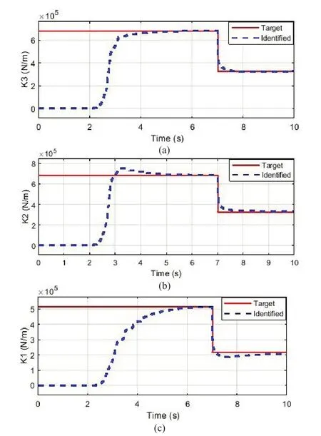
Fig.2 Comparison of the identified parameters and optimal control command performance: (a) estimated stiffness of the third floor, (b) estimated stiffness of the second floor,and (c) estimated stiffness of the first floor
The structural mean energy and minimum energy are calculated to obtain the energy coefficient.Roof floor information is considered as an unmeasured variable in computing the structural minimum energy.
In Fig.2, the stiffness decreases abruptly in each floor after 7 s.However, tracking stiffness variations of floors are well fulfilled without the initial assumption.Identified parameters converge in about 4 s.Furthermore,there is a good match between the identified stiffness and the target values.The case of the identified parameter with the optimized control as Integrated and the case of the target value with the optimized control as SAC Controlled are compared in Fig.3.On the one hand, after about 4 s, the identified value of the stiffness parameter converges to the target value.On the other hand, the stiffness variations detract abruptly after 7 s while it is well tracked.As demonstrated in Fig.3, the results are in excellent agreement in the two cases after convergence.
The energy coefficient is calculated according to Eq.(49).Since the value of the control force is optimized when the energy coefficient is employed, as shown in Fig.4, the value of the structural displacement in the combination of the parameter identification and control using the energy coefficient is greater than the value of the structural displacement in the case without using the energy coefficient.
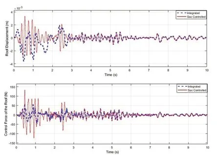
Fig.3 Comparison of the identified parameters and optimal control command performance in the roof floor:(a) structural displacement and (b) structural control force

Fig.4 Performance of the identified parameters with and without optimized control in the roof floor
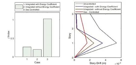
Fig.5 Comparison of the identified parameters and optimal control command performance with other cases: (a) energy index and(b) drift of floors

Table 1 Comparison of the identified parameters and optimal control performance with other cases
The integration of the parameter identification and control, indicated as Integrated, with and without energy coefficient and the integration of the target value and control with energy coefficient, indicated as SAC Controlled, are compared in Fig.5 and Table 1.
It is demonstrated in Fig.5(a) that the maximum energy from the structural vibration in the case of integrated with energy coefficient is more than the one without the energy coefficient.That is due to the fact that the value of the control force is reduced when the energy coefficient is applied.
In Fig.5(b), the proposed approach drift with the use of energy coefficient, due to applying controller, is still less than the drift of the uncontrolled structure.The vibration reduction of the structure is done satisfactorily.Table 1 confirms thatJ1andJ2indices augment in the integrated case of identification and control with the energy coefficient, and theJ3index declines.
It is assumed that there is no information regarding the displacement, velocity, and acceleration sensors of the second floor.The abrupt changes of stiffness are identified and structural vibration is adequately reduced.
Since the identified errors of parameters increased in the case without sensor information of displacement,
Fig.6 Comparison of the proposed approach performance with minimal information of sensors: (a) structural displacement error in the second floor and(b) structural control force error in the second floor velocity, and acceleration as compared with the one with full sensor information, the error(t) value is also increased in the control and displacement diagrams in Fig.6.
Yet, the error in the displacement response graphs is negligible, and the control signal with estimation values are in agreement with the control results of the target values.
4.2 Phase Ⅰ IASC-ASCE benchmark plant simulation

The structural mean energy and minimum energy are calculated to obtain the energy coefficient.Roof floor information is considered as an unmeasured variable in computing the structural minimum energy.
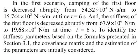
Noise is added to the seismic input with intensity of RMS 2%.The forgetting factors are:
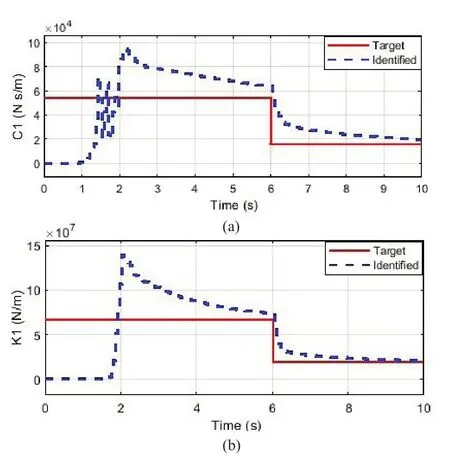
Fig.7 Comparison of the identified parameters and optimal control command performance of the first floor:(a) estimated damping and (b) estimated stiffness
In Fig.7, despite the presence of the added noise with RMS 2% to the seismic input, the structural damping and stiffness parameters converge in about 6 s and abrupt changes are well identified without the initial assumption of estimation.
As demonstrated in Fig.8, after around 3 s, the parameter identification is with a small error.Therefore,the control force in the integrated case corresponds to a value of the target of the SAC controlled case.According to Fig.9, when the energy coefficient is applied, the value of the control force decreases; thus, the value of displacement increases.Figure 10 clearly illustrates that the energy index is enhanced in the case with the energy coefficient compared to the one without optimization.Its drift, moreover, is less than the uncontrolled case.The optimization of the structural control force is carried out well via considering the values ofJ1andJ2increased indices in the integrated case with the energy coefficient(Table 2).

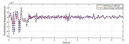
Fig.9 Performance of the identified parameters with and without optimized control in the first floor

Fig.10 Comparison of the identified parameters and optimal control command performance with other cases: (a) energy index and (b) drift of floors

Table 2 Comparison of the identified parameters and optimal control performance with other cases
To identify the stiffness parameters based on the presented formulas in Section 3.1, the covariance matrix and the estimation of the parameters are initially taken into consideration.
Noise is added to the seismic input with intensity of RMS 2%.The forgetting factors are:
In addition to the noise added with intensity RMS 2%to the seismic input, convergence of stiffness parameters is performed.Tracking the step variations in the stiffness of the floors is adequately conducted, and there is good agreement between the identified and target stiffness values in each change (Fig.11).
The diagrams in Fig.12 indicate an acceptable accuracy in the control force and displacement of the proposed method.The results in the online identification and optimal control case match the target values and optimal control case.The vibration reduction of the structure is also done satisfactorily.

Fig.12 Comparison of the identified parameters and optimal control command performance in the first floor:(a) structural displacement and (b) structural control force
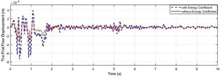
Fig.13 Performance of the identified parameters with and without optimized control in the first floor

Table 3 Comparison of the identified parameters and optimal control performance with other cases

Fig.14 Comparison of the identified parameters and optimal control command performance with other cases: (a) energy index and (b) drift of floors
The energy coefficient is calculated according to Eq.(49).It can be seen in Figs.13, 14 and Table 3 that the values of the energy index and structural displacement in the combination of identifying parameters and SAC control with the energy coefficient are higher than the case without energy coefficient since the value of the control force is reduced and optimized when the energy coefficient is employed.Furthermore, the value of RMS of displacement and absolute acceleration responses are high.However, the drift of the proposed approach is still less than the drift of the uncontrolled structure.
5 Conclusions
It is necessary to investigate an effective algorithm for the combination of online identification and adaptive control in time-varying systems.Thus, the current study evaluates an integrated approach when the control force is optimized calculating the probability density function of the structural energy so that the proposed method would be cost-effective.In the proposed method, the advantages of estimation and control methods while each performing their tasks are combined.Furthermore,the abrupt or gradual variations of structural physical parameters are identified online using MFRLS and minimal information of sensors.The noise intensity with different RMS is further added to the input measurement, and the identification is adequately conducted.Additionally, the energy from the structural vibrations is obtained, and the SAC control force can be computed simultaneously.The results reveal that as time progresses, the SAC control algorithm and energy coefficient reduce the structural vibration.Moreover,a first-order filter is employed to limit the response error of the structural control.The numerical study and phase I IASC-ASCE benchmark building is carried out to validate the effective performance of the proposed methodology.
杂志排行
Earthquake Engineering and Engineering Vibration的其它文章
- Reliability-based life-cycle cost seismic design optimization of coastal bridge piers with nonuniform corrosion using different materials
- Finite element model updating for structural damage detection using transmissibility data
- Experimental study on seismic reinforcement of bridge foundation on silty clay landslide with inclined interlayer
- A novel mitigation measure for normal fault-induced deformations on pile-raft systems
- Longitudinal vibration characteristics of a tapered pipe pile considering the vertical support of surrounding soil and construction disturbance
- Resilient performance of self-centering hybrid rocking walls with curved interface under pseudo-static loading
