A novel mitigation measure for normal fault-induced deformations on pile-raft systems
2024-02-23MohammadrezaJahanshahiNowkandehandMehdiAshtiani
Mohammadreza Jahanshahi Nowkandeh and Mehdi Ashtiani
Faculty of Civil Engineering, Babol Noshirvani University of Technology, Babol, Iran
Abstract: Evidence from recent earthquakes has shown destructive consequences of fault-induced permanent ground movement on structures.Such observations have increased the demand for improvements in the design of structures that are dramatically vulnerable to surface fault ruptures.In this study a novel connection between the raft and the piles is proposed to mitigate the hazards associated with a normal fault on pile-raft systems by means of 3D finite element (FE)modeling.Before embarking on the parametric study, the strain-softening constitutive law used for numerical modeling of the sand has been validated against centrifuge test results.The exact location of the fix-head and unconnected pile-raft systems relative to the outcropping fault rupture in the free-field is parametrically investigated, revealing different failure mechanisms.The performance of the proposed connection for protecting the pile-raft system against normal fault-induced deformations is assessed by comparing the geotechnical and structural responses of both types of foundation.The results indicate that the pocket connection can relatively reduce the cap rotation and horizontal and vertical displacements of the raft in most scenarios.The proposed connection decreases the bending moment response of the piles to their bending moment capacity,verging on a fault offset of 0.6 m at bedrock.
Keywords: normal fault rupture; failure mechanism; pile-raft system; pocket connection; finite element modeling
1 Introduction
The major consequences of ground shaking caused by earthquakes are the propagation of waves and permanent ground deformations (PGD).Engineering structures constructed near or on active faults that might be subjected to PGD and bedrock fault movement can result in heavy damage to buildings and foundations.The type of damage that occurred in the 1999 earthquakes in Turkey, the 2008 earthquake in China, and the Longmenshan fault, all of which created outcropping fault ruptures up to 9 m, have drawn many researchers’ attention to this subject.However, several cases have shown that a building was able to deviate the fault rupture away from itself (Anastasopoulos and Gazetas, 2007a; Faccioliet al., 2008; Ulusayet al.,2002).Anastasopoulos and Gazetas (2007b) provided a documented explanation of the interaction between fault rupture, soil, and an engineering structure.This type of foundation system was shown to be of significant importance in the response of the structures located in close proximity to an active fault.Extremely loaded structures that were built on contiguous and inflexible box-type foundations were more likely to cause diversion of a fault rupture.This means that engineering structures could successfully perform in the proximity of active faults, provided that the continuity and inflexibility of the foundation are considered.Experimental and numerical studies on the interaction between shallow foundation systems and dip-slip faults also have revealed that the failure mechanism of shallow foundations is primarily dependent upon foundation surcharge, width and flexibility, soil depth, and the relative space between the foundation and the outcropping rupture in the free field (Anastasopouloset al., 2009; Ashtianiet al., 2021;Bransbyet al., 2008a, 2008b; Gazetaset al., 2015; Loliet al., 2012; Ghafariet al., 2021).
Case histories of catastrophic earthquakes have shown different failure mechanisms of pile foundations subjected to PGD (Faccioliet al., 2008).This has stimulated many researchers to conduct experimental and numerical studies to secure additional insight into failure mechanisms, as well as the fault-resistant design of pile foundations subjected to dip-slip faults(Anastasopouloset al., 2013; Cai and Ng, 2016; Liet al.,2019; Linet al., 2020; Rasouli and Fatahi, 2019a; Tsatsiset al., 2011; Yao and Takemura, 2020; Yaoet al., 2021).Yaoet al.(2021) conducted two centrifuge tests to study the behavior of single pile-shallow foundations subjected to a reverse fault.It was found that the shallow foundation experienced high levels of displacement and rotation caused by the interaction of a reverse fault with single piles.Yao and Takemura (2020) studied the interaction of single piles and dip-slip faults using six centrifuge tests that were conducted in sand.The comparison between the internal forces of pile foundations caused by their interaction with dip-slip faults revealed that fault-induced forces to the piles in the reverse fault were significantly greater than those in the normal fault.
Cai and Ng (2016) investigated the interaction of pile foundations and normal faults in sand.The results revealed that the pile in the group that was located on the footwall sustained greater values of bending moment and displacement compared to a single pile because the two additional piles and the cap on the hanging wall side were dragged down sharply as the fault slip reached its maximum level.Liet al.(2019) conducted a smallscale physical sandbox test and numerical modeling to investigate the interaction of a pile group with a reverse fault rupture.They showed that fault rupture path propagation in the free field differs from that in the attendance of a pile group.Because the piles located in the shear region could detach and fail with the evolution of the fault offset at bedrock, they concluded that the relative location of pile groups must be situated away from the triangular shear area.
Damage caused by the interaction of a fault rupture with a structure has resulted in developing mitigation strategies to decrease the hazards pertaining to surface faulting (Anastasopoulos and Jones, 2019; Ashtianiet al., 2018; Bray, 2001; Fadaeeet al., 2016; Loliet al.,2018; Oettle and Bray, 2013; Rasouli and Fatahi, 2021;Sadraet al., 2020; Yanget al., 2020; Yao and Takemura,2020; Rojhaniet al., 2022).As stated, case histories have shown the successful performance of engineering structures that are constructed on stiffand continuous foundations.Nevertheless, the problem of permanent displacements has not been fully addressed, and in many cases such structures must be demolished.Moreover, the addition of extra rigidity to a foundation is not always cost-effective.Therefore, there is an increasing demand for the development of efficient fault mitigation methods(Anastasopoulos and Jones, 2019).Mitigation strategies can be classified into three categories.(1) Foundation strengthening: in this mitigation approach, which is used for dip-slip faults, a rigid foundation is placed underneath a building.Due to the rigidity of the raft, the building would revolve as an inflexible body without undergoing significant distress (Anastasopouloset al.,2009; Faccioliet al., 2008).(2) Directing fault ruptures away from the structure: with this strategy, a diaphragm wall or barrier is introduced to direct the fault rupture away from the engineering building (Anastasopoulos and Jones, 2019; Fadaeeet al., 2016; Oettle and Bray, 2013;Sadraet al., 2020; Yaoet al., 2020).This strategy seems to be of great interest because it can simply be exerted on engineering structures or monuments.(3) Diffusing fault-induced deformations: in this mitigation approach,the foundation is decoupled from the soil beneath it by installing a ductile fill below the foundation.This will spread fault-induced deformations over a broad zone and reduce fault-induced forces on the structure (Bray,2001).The earth fill must be profound and sufficiently plastic to effectively diffuse fault deformations.Because the breadth of the diffusion is strongly dependent upon earth fill expanse, an earth-fill with greater depth will result in better performance of structures subjected to fault-induced deformations (Oettle and Bray, 2013).Ashtianiet al.(2018) used high-density polyethylene(HDPE) geogrids for diffusing a reverse fault rupture.The results showed that geogrid reinforced layers could diffuse fault rupture to a broader area.Rasouli and Fatahi(2019a) proposed a novel pile-raft system to safeguard a superstructure from damages related to normal faulting.In their proposed composite foundation system the raft was decoupled from the soil by placing compacted fill of a desirable depth underneath the raft.The piles in close proximity to the hanging wall were linked to the raft through elastomeric pads.The other piles were separated from the cap by setting them beneath the earthfill layer.Numerical analysis revealed that the proposed foundation system showed acceptable/safe performance under large tectonic movement.
As stated, engineering structures built near a potentially active normal fault may undergo severe damage during an earthquake as a result of the combined effects of ground shaking and tectonic displacement.Hence, proposing a mitigation strategy protecting the structures from tectonic movements and ground shaking is of significant importance.The current study proposes a novel mitigation strategy to be used against permanent deformations of normal faults on piled raft foundations.The current work is of great value to geotechnical engineers because it introduces a practical solution to reduce normal fault-induced damage to piled raft foundations by considering the reduction of raft drift.
This research thoroughly studies the effectiveness of a novel connection between the raft and the piles,which has been proposed to mitigate normal fault rupture hazards to buildings.The single pile and pile group numerical models with a user subroutine were validated through centrifuge experiments performed to study their interaction with a normal fault.Following that validation, 3D numerical modeling of traditional and unconnected pile-raft systems was done to study the different failure mechanisms of the pile-raft systems subjected to a normal fault.This was accomplished by employing a wide-ranging parametric study on the relative distance of the raft edge to the outcropping fault rupture.The suitability of the proposed connection for reducing fault-induced damage was assessed through a comparison of raft rotation, raft vertical and horizontal displacement, and the bending moment response of the piles of traditional and unconnected pile-raft systems.
2 Problem outlines
The interaction between a fault rupture and a pileraft system has a high probability of failure.Figure 1(a)shows the worst-case scenario of the interaction between a fault rupture and a traditional pile-raft system when the fault rupture path propagates nearly underneath the raft.The strong interaction between the fault rupture and the pile-raft system in this failure mechanism can cause significant damage, including cap rotation, horizontal and vertical raft displacement, bending failure of piles and even separation of piles from the raft.However,there are two additional failure mechanisms that could occur during the interaction between a fault rupture and pile-raft systems.These include deviation of the fault rupture path from the right-hand side of the raft in the hanging wall, and outcropping of the fault rupture at the top surface away from the left-hand side of the raft due to the embedment of the entire pile-raft system in the hanging wall.These two mechanisms are associated with minimum damage to the pile-raft system compared to the failure mechanism (shown in Fig.1(a)).
In order to improve the performance of traditional pile-raft systems during faulting, an unconnected pileraft system with a pocket connection between the raft and the piles is proposed (Fig.1(b)).After installing circular drilled concrete piles in this pile-raft system, a nonfrictional mold is set on the peripheral and top surfaces of the piles head to prevent cap concrete from touching the piles.In order to connect the top of the pile head to the cap non-structurally, elastomeric bearing pads can be placed on top of the piles and underneath the molds.On the inner surface of the non-frictional mold, two lowfriction covers, such as polytetrafluoroethylene (PTFE)sheets are placed, covering the peripheral surface of the embedded length of the pile in the raft (Fig.1(c)).This can reduce the structural damage caused by the interaction between the normal fault and the pile-raft system.A low-friction cover should be glued to the peripheral surface of the embedded length of the pile in the cap, and another should be placed on the first cover to facilitate slippage at the pile-cap interface during faulting.Sadraet al.(2020) reported that PTFE sheets have a maximum friction coefficient of 0.1.In this type of pile-raft system,as the fault slip increases the piles can move downward without experiencing remarkable distress due to the lack of a structural connection between the raft and the piles.This leads to a reduction in the differential settlement of the raft (see Fig.1(b)).However, in traditional pileraft systems, as the fault slip increases the raft moves downward as a result of downdrag forces on the piles,which could cause excessive differential settlement in the raft as well as considerable distressing in the piles.This study emphasizes the performance of a novel pocket connection between the raft and the piles in order to mitigate normal fault-induced damage to piled raft foundations.
All piles and the cap were modeled as concrete,with Young’s modulus of 25 GPa, Poisson’s ratio of 0.2,and mass density of 2500 kg/m3.The pile-raft system consists of a group of 4 × 4 circular drilled concrete piles with diameters ofd= 1 m and length ofD= 15 m.The center-to-center distance of the piles is three times the diameter of each (3 m).The cap of the piles is square,with a thickness of 1 m and a width of 12 m.The thickness of the soil medium above the bedrock is 20 m.The mechanical characteristics of typical dense sand used for the parametric study of the interaction of the pile-raft systems and normal faults are shown in Table 1.
To simulate the normal fault used in numerical models, displacement was exerted to the boundaries with a dip angle ofα= 60° and a vertical displacementh.Fault displacement levels vary from 1% of soil medium thickness (0.2 m) to a maximum of 5% (1 m).As a result of the interaction between the fault rupture path and the pile-raft system, the cap will experience rocking and displacement.
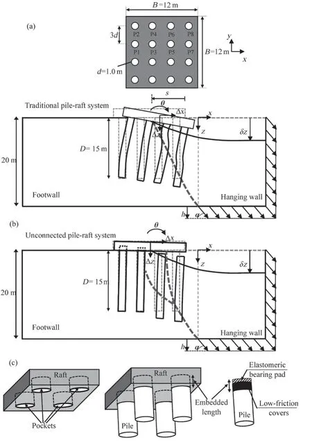
Fig.1 Schematic display of: (a) interaction between traditional pile-raft system and normal fault; (b) interaction between unconnected pile-raft system and normal fault;(c) details of the pocket connection
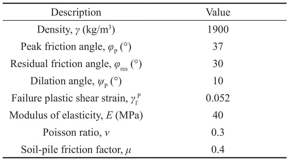
Table 1 Characteristics of sand utilized for parametric study of interaction of normal fault with pile-raft systems
Because in reality the position of the fault scrap will be unknown, the relative space between the pileraft system edge and the outcropping fault is the most important variable parameter in this study.When no structure exists at the top surface, the fault rupture path propagates through the soil medium without deviation or outcrops at the topsoil surface.Therefore, the location of the fault outcrop at the ground surface can be considered as the indicator of the variable parameter.The space between the right edge of the cap and the outcropping fault (s) should be taken into account as another indicator of this variable parameter.
3 Numerical modeling
Over the past few years, different numerical procedures have been used to simulate fault propagation in soil as well as the interaction of dip-slip faults with engineering structures (Anastasopouloset al.,2007; Oettle and Bray, 2017).Anastasopouloset al.(2007) developed a strain-softening constitutive law to investigate the propagation of dip-slip faults in sand.They concluded that the dip angle of a normal fault could vary regarding the fault rupture path outcrops,depending upon sand peak friction and the dilation angle.The developed constitutive model has been used in other studies, including Loliet al.(2011, 2012), to study the interaction between caisson foundations and dip-slip faults.Loliet al.(2011, 2012) concluded that the failure mechanisms were susceptible to the relative space between the caisson foundation and the outcropping fault rupture.Loliet al.(2018) used this FE code in another study for FE validation of hybrid foundations against experimental models.They concluded that the accuracy of numerical models in the prediction of centrifuge tests was strongly dependent upon using theφ,ψ-σVrelationship.
In this work the finite element (FE) software ABAQUS was utilized to simulate 3D models in order to investigate the interaction between traditional,unconnected pile-raft systems, and normal faults that propagate inside a sand layer.The coefficient ofK0in all numerical models was determined through the use of Jaky’s formula (i.e.,K0= 1 - sinφ, whereφis the internal friction angle of sand).The pile-raft system was placed at the ground surface, and then the entire model was subjected to gravity loading.The cap surface was applied to a load of 120 kPa to simulate the load of a 12-story building.The bottom and side boundaries (only for the hanging wall) of the models were released and then subjected to a degree of displacement that simulated a normal fault, with a dip angle ofα= 60° and an offset ofh= 1 m at bedrock.
3.1 Properties of numerical models

Fig.2 Typical FE mesh of models: (a) soil and pile-raft system; (b) hybrid pile
Figure 2 shows the typical FE mesh utilized for the discretization of a pile-raft system and soil medium in the numerical models.In order to model the soil medium,cap, and piles, solid eight-node reduced-integration continuum elements (C3D8R) were used.While the piles are modeled as solid elements, the bending moment of the piles cannot be acquired directly from this type of element; thus, the hybrid approach was used to overcome this limitation (Zhang and Liu, 2017; Zhang,2014; Anastasopouloset al., 2013).In this approach, a column of beam element (B31) is embedded along the central axis of piles, as shown in Fig.2(b).The flexural rigidity of the beam elements was set at 10-6times less than that of the solid elements of the piles so that they do not affect the structural response of the piles.The bending moments of piles are obtained by multiplying the bending moment resulting from the beam element,using a scaling factor of 106(Banerjeeet al., 2014).The essential advantages of this approach are that: (1)this approach is able to consider the influence of pile volume (pile’s periphery) and (2) the pile bending moment is readily calculated by means of the beam elements (Zhang, 2014).
The size of the elements close to the pile-raft system and fault rupture path and along the soil-pile interface was the smallest in size (0.5 m).However,as the distance from the piled raft and the potential fault rupture path increased, larger meshes were used.Different distances of the pile-raft system edge from the fault outcrop resulted in varying paths of fault rupture in the soil medium.The meshes used for numerical models should be the finest along these paths.As a result, the meshes utilized in numerical models ranged from 62525 (ats/B= 0.5) to 69440 (ats/B= 1.5).The soil medium thickness was 20 m and the edge-to-edge length of the models was 2.5 times the thickness of the soil and four times the breadth of the cap (50 m), as shown in Fig.2.Because the numerical model was symmetric with respect to theXZplane, only half of the model was taken into account in order to reduce the analysis time.
Because this work aims to study the interaction between a pile-raft system and a normal fault, only the bottom boundary face was used to simulate the underlying bedrock movement.To simulate the fault rupture propagation from the bedrock, the bottom boundary was split into two parts: (1) the left side remained stationary in the numerical models, which is representative of the footwall, and (2) the right side was subjected to tectonic movements which are representative of the hanging wall.The boundaries with which the hanging wall moved downwards at a dip angle ofα= 60° and vertical displacement ofh= 1 are shown in Fig.2(a).
The pile and cap were assumed to be elastic, and the characteristics of concrete were assigned to them.In order to numerically model the proposed connection,the places of the piles in the cap were first extruded.Next, the piles were placed within the holes in the raft.The soil-pile, soil-raft, and pile head-raft (solely for the pocket connection) interface were assumed to follow the hard contact algorithm, which allows for the surfaces between pile, raft, and soil to slide and detach during analysis.To model the tangential movement between the stated surfaces, Coulomb’s frictional method was utilized.Such tangential displacement occurs as surface traction overtakes the threshold interface shear strength.This method converts interface pressure into shear strength by means of a predetermined friction factor(Nowkandeh and Choobbasti, 2021).
3.2 Constitutive model
In recent years, many researchers have demonstrated that one of the most crucial factors affecting the propagation of fault rupture in sand, as well as the emergence of fault rupture at the topsoil surface, is the post-peak behavior of soil (Anastasopouloset al., 2007;Oettle and Bray, 2017).Generally, when dense sandy soils experience large values of shear stress they show post-peak, strain-softening behavior.In this work the Mohr-Coulomb constitutive model in ABAQUS was modified by employing a user subroutine that considers the post-peak softening behavior of sand, similar to a study done by Anastasopouloset al.(2007).In this particular FE code, the ultimate mobilized friction angle(φP) and dilation angle (ψP) of the soil decrease linearly to their residual amounts (φresandψres= 0) as the octahedral plastic shear strain () increases:
in whichDis the depth of the direct shear test,dFEis mesh size, andNis centrifugal acceleration.The horizontal displacements (δxy,δxp, andδxf) are determined by using the direct shear test at the end of strain-softening.
3.3 Validation of numerical models
The validation of numerical models through centrifuge tests can provide insight into the capacity of the programming software to simulate and obtain similar experimental and field responses (Ziotopoulou,2018).The interaction between pile foundations and a normal fault was validated by using centrifuge model tests conducted at the Hong Kong University of Science and Technology (Cai and Ng, 2016).The tests were carried out at a centrifugal acceleration of 50 g, using a model container to study the efficacy of fault-induced permanent ground deformation on the behavior of a single pile and a group of 3 × 1 piles.A normal fault was exerted to the model boundaries at a dip angle ofα=70° and a vertical displacement component of 42 mm(2.1 m at prototype scale).The width, length, and height of the soil model were 350 mm × 1170 mm × 400 mm,respectively, which were equal to 17.5 m × 58.5 m × 20 m at the prototype scale.The general characteristics of the experimental test are shown in Fig.3.The piles used in the experiments consisted of aluminum with a hollow,square cross-section, some of which had been coated with epoxy resin for the installation of a strain gauge.The width and thickness of the piles were 10 mm and 0.7 mm, respectively, and they were coated with an epoxy resin with a thickness of 1.5 mm, and Young’s modulus of 2 GPa was applied.All piles in the pile group were perpendicular to the axis of the normal fault and were connected to a flexible cap.As Fig.3 shows, the position of the PF in the pile group model (or PS in the single pile model) was chosen such that the fault rupture path intersected the center of the embedded pile shaft in the soil.The spacing between the piles was 78 mm and the cap consisted of aluminum, with a thickness of 13 mm.
Toyoura sand (Ng and Lu, 2014) with a relative density of 65% was used under dry conditions to prepare the sample by using the dry pluviation method.The soil properties are shown in Table 2.The friction angle of the soil-pile interface was 29°.
The comparison between the experimental test images and the numerical displacement contours of the interaction of the single pile and pile group with a normal fault are shown in Figs.4 and 5, respectively.The results demonstrate that the numerical model simulated the propagation of a normal fault and its interaction with a single pile and pile group.As found in the experimental centrifuge tests, the numerical results showed that the fault rupture path propagated through the soil at an angle that was greater than the dip angle of the bedrock(Figs.4(b) and 5(b)).
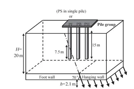
Fig.3 Characteristics of centrifuge model test used to investigate pile-normal fault interaction at prototype scale (Cai and Ng, 2016)
The comparison of the numerical modeling and the experimental model of ground displacement profile caused by the interaction of the normal fault with a single pile and pile group are shown in Fig.6.This comparison was performed for different vertical displacement levels of a normal fault at bedrock (h).The comparison revealed that the numerical model showed relatively good agreement with the experimental results and has been able to model the effect of the presence of piles on the ground surface profile.The piles head rotation and their bending moment response resulting from the normal fault slip are shown in Fig.7.As seen in Fig.7(a), the numerical model was able to estimate the amount of pile rotation and its increase with the evolution of normal fault slip at bedrock.Figure 7(b) represents the bending moment response of two piles of the pile group in both the centrifuge test and numerical model at a fault offsetof 2.1 m.As seen in Fig.7(b), the maximum bending moment of both the piles in numerical and experimental models was positive, representing that the piles are bending toward the hangingwall.
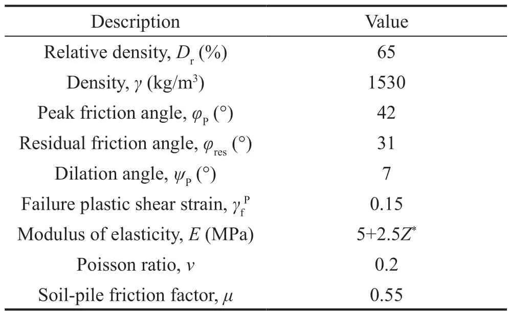
Table 2 Strength and deformation properties of sand used for numerical validation (Ng and Lu, 2014)

Fig.4 Experimental and numerical models of single pile interaction with normal fault at dip angle of α = 70°:(a) deformed centrifuge model test (Cai and Ng, 2016);(b) deformed vertical displacement contour of numerical model
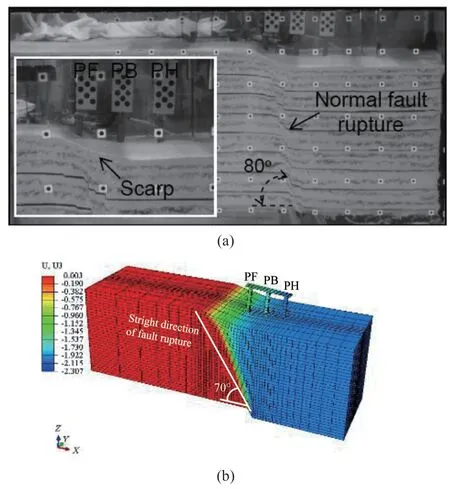
Fig.5 Experimental and numerical models of pile group interaction with normal fault at a dip angle of α = 70°:(a) deformed centrifuge model test (Cai and Ng, 2016);(b) deformed vertical displacement contour of numerical model
4 Results and discussion
In recent years, many researchers have shown that the failure mechanism and fault-induced deformations of the deep and shallow foundations, buried pipelines,and tunnels are primarily dependent upon the distance of such engineering structures to the fault rupture path(Ghalandarzadehet al., 2016; Rasouli and Fatahi, 2019a,2019b; Caiet al., 2019; Fadaeeet al., 2020; Sabagh and Ghalandarzadeh, 2020; Ashtianiet al., 2021; Agalianos and Anastasopoulos, 2021; Naeij and Soroush, 2021).In the current work, the space between the right edge of the raft and the outcropping fault rupture in the free field (s) was made dimensionless by dividing it by the width of the raft (B).At first, a free field model was numerically analyzed to specify the location of the outcropping fault rupture without considering the pileraft system.Subsequently, the pile-raft systems were placed at various relative spaces between the raft and the outcropping fault rupture in the free field (s/B=0.5, 1, 1.5) in order to investigate various interaction mechanisms between the traditional and unconnected pile-raft systems and the normal fault.Next, the piles were placed in the soil medium such that the right row piles were either inside or near the hanging wall, and the left row piles were either in or nearby the footwall.In this section, the predictions for the fault rupture propagation path, differential settlement of the raft, horizontal and vertical displacement of the raft center, and bending moment of the piles are presented and discussed.

Fig.6 Experimental and numerical ground surface vertical displacement profile for: (a) single pile; (b) pile group model
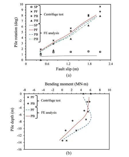
Fig.7 Experimental and numerical responses of single pile(SP) and pile group (PF, PB, and PH): (a) piles head rotation for different values of fault offset at bedrock;(b) bending moment response of piles of pile group (PF and PB) at fault offset of 2.1 m at bedrock
4.1 Outcropping fault rupture at s/B = 0.5
In this scenario the pile groups were located such that, if undisturbed, the fault rupture would propagate through piles P5 to P8 and emerge in front of the center of the raft.As Fig.8 shows, the fault rupture path was modified by the pile groups in the traditional and unconnected piled raft and deviated upward along piles P7 and P8.Furthermore, the cap detached from the surrounding soil at the right-hand edge of the raft in both pile-raft systems.A similar failure mechanism was reported by Rasouli and Fatahi (2019a) when the fault rupture path intersected the left row piles ats/B= 0.75.
The hanging wall’s downward movement was highly likely to downdrag the right row piles in both pile-raft systems.Nonetheless, because the fault rupture was deviated by the pile groups in both the traditional and unconnected pile-raft systems (see Fig.8), the piles experienced slight displacement (the 3D settlement of pile groups is shown in Fig.9).It should be noted that the piles at the left (P1 and P2) underwent a small downward movement that caused a decrease in the differential settlement of the pile-raft systems.

Fig.8 3D deformed FE plastic strain contours of interaction between pile group and normal fault at fault offset of h = 1 m at s/B = 0.5: (a) traditional pile-raft system;(b) unconnected pile-raft system
Figure 10(a) shows that the differential settlement of the traditional and unconnected pile-raft systems added to a maximum value of 0.047 m as the fault slip reached 1 m.However, as shown, the differential settlement of the rafts in the traditional and unconnected pile-raft systems rarely increased beyond the fault offset of 0.1 m.This occurred because, as the numerical results indicated, for a fault slip of about 0.1 m, the ruptured fault had already outcropped before reaching the center of the rafts (see Fig.8).Therefore, any further increase in the fault offset at bedrock would simply increase the height of the fault scrap and would not noticeably affect the differential settlement or rotation of the caps.Even though pile-raft systems can somehow act as a mitigation measure when subjected to a normal fault ats/B= 0.5, Liet al.(2019)concluded from numerical modeling of the interaction of pile-raft systems and thrust faulting that maximum cap rotation is highly likely to occur at this scenario for reverse faults.

Fig.9 Five times scaled-up 3D FE vertical displacement contours of pile group before and after fault rupture at fault offset of h = 1 m at s/B = 0.5: (a) traditional pile-raft system; (b) unconnected pile-raft system
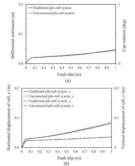
Fig.10 Effect of evolution of fault slip at bedrock on the raft response at s/B = 0.5: (a) raft rotation and differential settlement; (b) horizontal and vertical displacement of raft center
As shown in Fig.10(b), when the fault offset at bedrock increased to 1 m, the horizontal and vertical displacement of the center of the traditional and unconnected pile-raft systems increased to maximum amounts of 0.083 m and 0.035 m, respectively.Nevertheless, the ultimate displacements of the rafts occurred only during the primary levels of fault propagation at bedrock.This means that the piles were forced to experience a downdrag movement by the propagation of the fault rupture from the bedrock level,as long as it reached the ground surface.After that they did not experience any further downward movement.Similarly, Loliet al.(2018) found that when dip-slip faulting intersects hybrid foundations in the footwall side corner, the structure experiences a minor degree of displacement.
Figure 11 shows the bending moment response of the piles for traditional and unconnected pile-raft systems corresponding to the fault offset of 1 m at bedrock ats/B= 0.5.As shown, the bending moment of the piles in both pile-raft systems was well below the maximum capacity, even for a fault offset of 1 m due to the deviation of the fault rupture when it struck piles P7 and P8.As seen in Figs.11(c) and 11(d), the bending moment of most of the piles barely increased after the early stages of fault propagation.This is exactly the same result as was the differential settlement and displacements of the center of the rafts, as displayed in Fig.10.
4.2 Outcropping fault rupture at s/B = 1

Fig.11 Response of piles to interaction between pile group and normal fault at s/B = 0.5: (a) bending moment of traditional pileraft system piles and; (b) unconnected pile-raft system piles; (c) evolution of bending moment of traditional pile-raft system piles and; (d) unconnected pile-raft system piles
In this scenario-case the pile group was set near the hanging wall, so that, if undisturbed, the fault rupture would propagate nearly beneath the center of the raft and emerge at the left-hand edge of the raft.As Fig.12(a)shows, the fault rupture experienced a bifurcation when it reached the piles of the traditional pile-raft system,such that one fault rupture branch appeared along the soil-pile interface of the piles on the right (P7, P8).The second propagated between the two rows of the piles on the right (P5, P6 and P7, P8), and intersected P5 and P6 at about mid-height and were slowly diffused.As seen in Fig.12(b), the first branch of the fault rupture experienced a similar bifurcation to the traditional pileraft system.However, the second fault rupture branch emerged along the P5 and P6 soil-pile interface and rapidly propagated to the ground surface, which caused plastic deformation of the soil below the raft at the heads of piles P5 and P6.In addition, a third fault path emerged beneath piles P5 and P6, propagated through the soil below the center of the raft, and finally intersected with P3 and P4 at about mid-height.Although the proposed cushioned piled raft foundation presented by Rasouli and Fatahi (2019a) made the fault rupture path experience the same bifurcation undergone by pocket connection in this study, this bifurcation almost occurred around the piles head.The clockwise rotation of the foundation in the traditional and unconnected pile-raft systems caused extensive soil yielding along the soil-pile interface of piles P1 and P2.However, as Fig.12(b) shows, this plastic deformation seems to be less for the unconnected pile-raft system because of the decrease in the cap rotation in the unconnected pile-raft system.
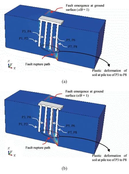
Fig.12 3D deformed FE plastic strain contours of interaction between pile group and normal fault at fault offset of h = 1 m at s/B = 1: (a) traditional pile-raft system;(b) unconnected pile-raft system
As Fig.13 shows, the right row of piles, including P5 to P8, was exposed to extreme downdrag when the hanging wall moved downward, although piles P1 to P4 seemed to resist the movement because they became fixed to the footwall.Hence, as seen in Fig.13(a), the fixed connection between the piles and the cap made the cap track the piles’ movements, which resulted in a considerable differential settlement of the raft.However,as Fig.13(b) shows, the pocket connection between the piles and the raft acted to disconnect piles P7 and P8 from the raft, forcing them to follow the hanging wall movement.As a result, the differential displacement of the raft decreased without generating notable distress in piles P7 and P8.Figure 13 also shows that, in both traditional and unconnected pile-raft systems, piles P1 and P2 were pulled out owing to being essentially fixed on the footwall.
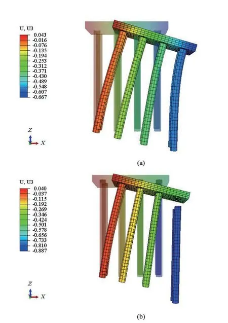
Fig.13 Five times scaled-up 3D FE vertical displacement contours of pile group before and after fault rupture at fault offset of h = 1 m at s/B = 1: (a) traditional pile-raft system; (b) unconnected pile-raft system
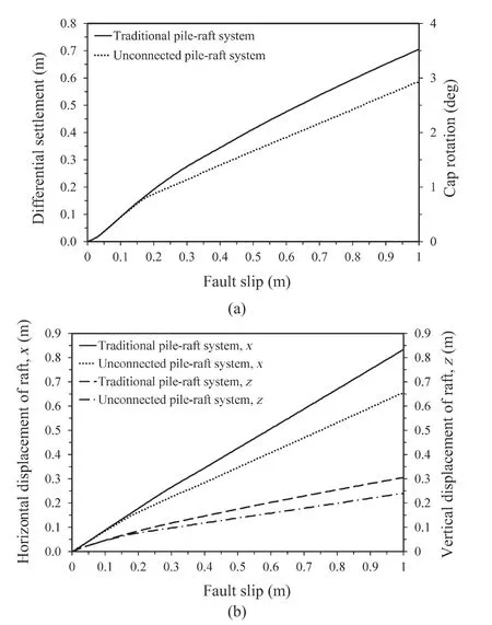
Fig.14 Effect of evolution of fault slip at bedrock on the raft response at s/B = 1: (a) raft rotation and differential settlement; (b) horizontal and vertical displacement of raft center
Unlike the previous scenario, in which the pile groups diverted the fault rupture ats/B= 0.5, the differential settlement of the traditional pile-raft system(including cap rotation) experienced a constant increase in its amount as the fault offset reached 1 m at bedrock(0.704 m), as shown in Fig.14(a).Similar observations were reported in the work of Cai and Ng (2016) and Caiet al.(2022), in which the tilting of the cap of the pile group towards the hanging wall rose continuously as the fault offset at bedrock increased to its maximum value in the centrifuge and numerical models, respectively.In addition, as shown in Fig.14(b), the horizontal and vertical displacement of the center of the raft of the traditional pile-raft system increased continuously to maximum amounts of 0.832 m and 0.305 m, respectively,as the fault offset at bedrock (h) reached 1 m.
Figure 14(a) illustrates that the differential settlement of the unconnected pile-raft system was similar to that for the traditional pile-raft system, as the fault offset reached 0.2 m.This indicates that the pocket connection between the piles and the cap must reach a critical fault slip value in order to become activated.In other words,the piles should experience a specific fault-slip threshold to disconnect from the raft and be entirely released.However, the differential settlement of the unconnected pile-raft system was less than the correspondent amounts for the traditional pile-raft system.After a fault offset of 0.2 m, it increased gradually to 0.582 m as the fault offset (h) reached its maximum value at bedrock (1 m).This value was 17% lower than the corresponding amount for the traditional pile-raft system.Figure 14(b)represents that when fault offset at bedrock reached 1 m,the horizontal and vertical displacement of the center of the unconnected pile-raft system increased continuously to 0.653 m and 0.241 m, respectively, which were nearly 21% lower than the corresponding values for the traditional pile-raft system.This difference is due to the disconnection of piles P7 and P8 from the raft (see Fig.13), thereby reducing the vertical and horizontal displacement of the cap.
Figure 15 shows the bending moment responses of piles for the traditional and unconnected pile-raft systems corresponding to a fault offset ofh= 1 m ats/B= 1.As seen in Fig.15(a), the maximum structural response of piles P1, P2, P5, and P6 was higher than the bending moment capacity, and it was much higher for piles P7 and P8.In addition, as Fig.15(a) indicates, the maximum structural response of piles P5 to P8 fixed on the hanging wall appeared at the pile head.For those embedded in the footwall (P1 to P4), the maximum bending moment occurred at about mid-depth.This was similar to the observation of Anastasopouloset al.(2013) wherein the fault rupture path propagated between two rows of a group of 2 × 4 circular piles.Nevertheless, as shown in Fig.15(b), the bending moments of piles P7 and P8 in the unconnected pileraft system decreased to their minimum values for a fault slip of 1 m.Furthermore, the maximum bending moments of piles P5 and P6 decreased to their bending moment capacity below the pile head.This could have occurred because of the different failure mechanisms of the unconnected pile-raft system.The second branch of the fault rupture propagated to the ground surface (see Fig.12) and caused milder stressing of piles P5 and P6.
Figures 15(c) and 15(d) show the evolution of the maximum bending moments for the piles of the traditional and unconnected pile-raft systems.As Fig.15(c)represents, the bending moments of piles of the traditional pile-raft system gradually increased as the fault slip reached 1 m.Furthermore, the bending moments of piles P5 to P8 exceeded their maximum capacity at a fault slip of about 0.2 m.By contrast, the bending moments of all piles were well below their maximum capacity before a fault offset of 0.5 m at bedrock in the unconnected pile-raft system.In the same way, the proposed cushioned pile-raft system presented by Rasouli and Fatahi (2019a) noticeably reduced the bending moment response of the piles.In addition, as shown in Fig.15(d), the bending moments of piles P7 and P8 slowly increased to a maximum value at a fault slip of 0.3 m and then gradually decreased to a minimum value when the fault offset reached 1 m.This again reveals that the pocket connection between the raft and the piles requires a minimum fault slip in order to totally disconnect from the raft and relax the bending moment of the piles.However, the bending moment response of the piles in the proposed cushioned piled raft foundation,as put forth by Rasouli and Fatahi (2019a), experienced a continuous increase as the fault offset reached 0.6 m at bedrock whens/B= 1.1.This is because in their proposed mitigation strategy the piles were completely disconnceted from the raft.

Fig.15 Response of piles to interaction between pile group and normal fault at s/B = 1: (a) bending moment of traditional pile-raft system piles and; (b) unconnected pile-raft system piles; (c) evolution of bending moment of traditional pile-raft system piles and; (d) unconnected pile-raft system piles
4.3 Outcropping fault rupture at s/B = 1.5
In this scenario-case, the pile groups were set much closer to the footwall, such that, if undisturbed, the fault rupture could have passed underneath the pile toes and outcropped at the ground surface away from the left-hand edge of the raft.Similar to the results of the previous case fors/B= 1 (see Fig.12), Fig.16(a) shows that the fault rupture path branched as soon as it intersected the piles beneath the traditional pile-raft system.The two bifurcations of the fault rupture appeared along the soilpile interface of piles P3, P4 and P1, P2, then intersected them at about mid-height and slowly diffused.A third branch propagated between the two rows of the piles on the left (P1, P2 and P3, P4), intersected P1 and P2 at about their toes, and outcropped in the ground surface well beyond the foundation.Figure 16(b) shows that the first and third branches of the fault rupture displayed a similar bifurcation of the traditional pile-raft system.The second fault rupture bifurcation appeared along piles P1 and P2 at the soil-pile interface and propagated slowly towards the pile heads, resulting in plastic deformation of the soil at the ground surface.

Fig.16 3D deformed FE plastic strain contours of interaction between pile group and normal fault at fault offset of h = 1 m at s/B = 1.5: (a) traditional pile-raft system;(b) unconnected pile-raft system
As Fig.17 represents, the piles in both the traditional and unconnected pile-raft systems were dragged down extremely because they were essentially embedded in the hanging wall.As Fig.17(a) shows, the raft in the traditional pile-raft system was forced to track the downward displacement of the piles, resulting in a noticeable vertical displacement of the raft.By contrast,because piles P5 and P6 were disconnected from the raft in the unconnected pile-raft system, vertical displacement decreased at the center of the raft.This led to a rather straightforward movement of piles P5 and P6,which experienced milder distress.Figure 17(b) shows that the vertical displacement of the left-hand edge of the raft in the unconnected pile-raft system decreased after the propagation of the second bifurcation of the fault rupture path to the top surface of the ground (see Fig.16).However, the right-hand edge of the raft experienced a similar vertical displacement of the traditional pile-raft system, as it essentially was sitting on the hanging wall.As a result, the differential settlement of the unconnected pile-raft system in this scenario was slightly greater than that of the traditional one.
Figure 18(a) shows that the level of differential settlement of the traditional pile-raft system underwent a constant increase in its value, as the fault offset level ended at 1 m at bedrock (0.476 m).Unlike the previous scenario in which the pocket connection between the raft and the piles caused a decrease in the differential settlement of the raft ats/B= 1, Fig.18(a) shows that the differential settlement of the unconnected pile-raft system (including a clockwise cap rotation) increased to 0.531 m at a fault offset ofh= 1 m at bedrock.This value was 11% higher than the corresponding amount for the traditional pile-raft system.Nevertheless, the cushioned pile raft system that was suggested by Rasouli and Fatahi (2019a) could significantly reduce the differential steelement of the raft in the same scenario.This may be regarded as the most important advantage of the cushioned piled raft foundations when they are subjected to a normal fault ats/B= 1.5.As reported in the previous scenario-case, the differential settlement of the unconnected pile-raft system was similar to that of the traditional pile-raft system before the fault offset reached 0.2 m at bedrock.Figure 18(b) shows that the horizontal and vertical displacement at the center of the traditional pile-raft system increased linearly to 0.732 m and 0.822 m, respectively, as the fault offset reached 1 m,which was nearly 6% less than the corresponding values for the unconnected pile-raft system.This agrees with the results of a series of centrifuge tests conducted by Yaoet al.(2021), Yao and Takemura (2020), and Ashtianiet al.(2016), in which single piles and shallow foundations underwent a constant displacement while the fault slip increased.

Fig.17 Five times scaled-up 3D FE vertical displacement contours of pile group before and after fault rupture at fault offset of h = 1 m at s/B = 1.5: (a) traditional pile-raft system; (b) unconnected pile-raft system
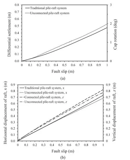
Fig.18 Effect of evolution of fault slip at bedrock on the raft response at s/B = 1.5: (a) raft rotation and differential settlement; (b) horizontal and vertical displacement of raft center
As shown in Fig.19(a), the bending moments of most piles were higher than their moment capacities.The maximum bending moment of piles P3 to P8, which was essentially fixed on the hanging wall, occurred at their heads, and they experienced similar bending behavior throughout their lengths.This was similar to the results of the work of Rasouli and Fatahi (2019a), Anastasopouloset al.(2013), and Liet al.(2019), in which the maximum value of the bending moment of the piles was where those piles head when most of the piles of the pile groups are embedded in a hanging wall during faulting.The structural response of the piles in the unconnected pile-raft system experienced milder distress at a fault slip of 1 m, especially at piles P5 and P6, which became disconnected from the raft during faulting.Figure 19(c)indicates that the maximum bending moments of piles P3 to P8 in the traditional pile-raft system greatly exceeded their bending moment capacities, as the fault offset (h) reached 0.4 m.However, in the unconnected pile-raft system, the maximum bending moments of the piles were well below their capacity, with a fault slip of about 0.6 m.It should be noted that when piles P5 and P6 became disconnected from the raft, their bending moment response with the evolution of the fault slip experienced a significant decrease (see the shallower slope of curves shown in Fig.19(d).
4.4 Further investigation into faulting
The numerical results showed that pile groups exerted a considerable influence on the fault rupture path, with a fault offset of 1 m at bedrock, causing a bifurcation or diffusion.Nevertheless, the crucial factor affecting the failure mechanism and the performance of the piles was the relative space between the cap and the outcropping fault rupture (s/B).Therefore, a parametric study was done to assess the response of the pile groups to this variable parameter.Differents/Bvalues were chosen so that the fault rupture pathed between every two rows of piles when propagated exactly beneath the rafts.Subsequently, the corresponding differential settlement values of the raft, horizontal and vertical displacement of the center of the raft, and the maximum bending moment of the piles for the traditional and unconnected pile-raft systems were compared.Figure 20 shows the response of the traditional and unconnected pile-raft systems to varying values ofs/Bfor different fault offsets, which ranged from 0.1 m to 1 m at bedrock.
As Fig.20 represents, the differential settlement, as well as horizontal and vertical displacement at the center of the raft for both the traditional and unconnected pile-raft systems, experienced a minor increase ass/Bincreased from 0 to 0.5.This happened because the fault rupture path intersected the right row piles and deviated away from the piled foundation.As a result, the piles remained rather fixed on the footwall without undergoing considerable flexural stress.Figures 20(a) to 20(d) show that as the intersection of the fault rupture approached the left row piles (1.2 ≥s/B> 0.5), the differential settlement and horizontal displacement of the raft noticeably increased, reaching a maximum value ats/B= 1.2 (the worst-case scenario), gradually decreasing tos/B= 1.5.When the interaction of the fault rupture path and the piles Fig.19 Response of piles to interaction between pile group and normal fault ats/B= 1.5: (a) bending moment of traditional pileraft system piles and; (b) unconnected pile-raft system piles; (c) evolution of bending moment of traditional pile-raft system piles and; (d) unconnected pile-raft system piles became negligible (s/B= 2), the raft experienced an anticlockwise rotation.This is because only the soil beneath the left row piles (P1 and P2) underwent considerable plastic strain, leading to a significant settlement of the right-hand edge of the rafts.As a result, in this scenario(s/B= 2), the differential settlement (rotation) of the rafts in both pile-raft systems was in direct contrast with other scenarios (1.5 ≥s/B> 0.5).Ats/B= 2.5, the differential settlement of both rafts was the least marked because the entire system was embedded in the hanging wall, resulting in the movement of the system with the hanging wall without experiencing any rotation.The peak differential settlement and horizontal displacement of the raft of the unconnected pile-raft system, at a fault offset of 1 m (s/B= 1.2), decreased by 14% and 20%,respectively, compared to the corresponding amounts of the traditional pile-raft system.Despite the fluctuation of the differential settlement of the rafts for varying values ofs/B, the vertical displacement of the raft for both the traditional and unconnected pile-raft systems increased continuously ass/Brose from 0 to 2.5 at different levels of fault slip, ending at 1 m whens/Barrived at 2, for a fault offset of 1 m at bedrock.

Fig.20 Effect of s/B on the raft response at different levels of fault offset at bedrock: (a) differential settlement of traditional pile-raft system; (b) unconnected pile-raft system; (c) horizontal displacement at center of raft of traditional pile-raft system; (d) unconnected pile-raft system; (e) vertical displacement at center of raft of traditional pile-raft system;(f) unconnected pile-raft system
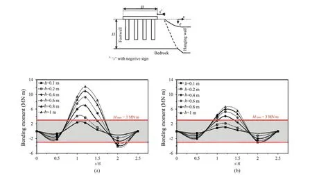
Fig.21 Effect of s/B on the pile response of piled raft foundations at different fault offset values at bedrock: (a) maximum/minimum bending moment in the pile of traditional pile-raft system; (b) unconnected pile-raft system
Figure 21 shows the bending response of piles in the traditional and unconnected pile-raft systems at different fault offset levels for different values ofs/B.As Fig.21 shows, the maximum bending moment response of piles occurred ats/B= 1.2 (the worst case) where the fault rupture path propagated primarily between the two rows of piles at the center of the raft (P3, P4 and P5, P6).In this case, the right row piles were dragged downward as the hanging wall moved and the left row piles resisted movement.As a result, the piles experienced remarkable distortion and bending moment response in the traditional pile-raft system, although this response was much less for the piles of the unconnected pile-raft system due to the disconnection of the piles from the raft during hanging wall movement.It was noted that the peak bending moment of the pile in the unconnected pileraft system at a fault offset of 1 m (s/B= 1.2) decreased by 50% compared to that of the corresponding pile in the traditional pile-raft system.
It could be concluded from studying Fig.21(b) that the bending moment response of all piles for all scenarios was nearly reduced to their bending moment capacity of 3 MN.m at a fault offset of 0.6 m in the unconnected pile-raft system.In addition, the piles experienced structural yielding ats/B= 1, 1.2, and 1.5 at higher fault slip values (h> 0.6).However, it is expected that the piles could escape this structural yielding with a rather extreme reinforcement ratio.
5 Conclusions
In the current study, a novel connection between the raft and the piles has been proposed to protect the piled raft systems from severe structural damage caused by normal fault rupture.In this proposed connection,the piles are separated from the raft by the elastomeric bearing pads and low-friction sheets.Because the failure mechanism and the response of the foundation systems are primarily dependent upon the exact location of the piled raft foundation with regard to the outcropping fault, different scenarios were numerically studied.The results obtained from the fault-induced responses of the unconnected pile-raft system were compared with those of a traditional pile-raft system, such as the differential settlement of the raft, horizontal and vertical displacement at the center of the raft, as well as the bending moments of the piles.The following conclusions may be drawn from the results of this study:
(1) The traditional and unconnected pile-raft systems experienced similar failure mechanisms ats/B= 0.5 because the fault rupture path deviated away from the piled foundations as soon as it struck the right row piles.This resulted in minor differential displacement in both rafts, as well as the smallest bending moment response of the piles.
(2) The worst-case scenario for the foundation systems occurred when the fault rupture path propagated approximately underneath the raft (s/B= 1.0-1.2), leading to extensive distress in the piles, as well as large differential settlement and horizontal displacement values for the raft in the traditional pile-raft system.However, the bending moment response of most piles significantly decreased regarding their bending moment capacity in the unconnected pile-raft system due to the disconnection of the piles from the raft.This novel connection could also decrease the cap rotation as well as the horizontal and vertical displacement of the raft by almost 20%.
(3) When the piles became essentially embedded in the hanging wall and the propagating fault rupture intersected the left row of piles (s/B= 1.5), the right edge of the rafts was dragged substantially downward in both traditional and unconnected pile-raft systems because they were essentially sitting on the hanging wall.However, the left edge of the raft in the unconnected pile-raft system saw in itself a reduction in its vertical settlement in this scenario due to the disconnection of the piles from the raft.As a result, the differential settlement of the raft rose slightly.This could be regarded as the most significant limitation of the proposed connection,judging solely from this scenario.
(4) The unconnected pile-raft system successfully decreased the bending moment response of the piles to below their bending capacities in all scenarios, as the fault slip reached 0.6 m at bedrock.Beyond a fault slip value of 0.6 m, milder distress in the piles of the unconnected pile-raft system was observed compared to the bending moments of the correspondent piles of the traditional pile-raft system, which could be resolved with greater reinforcement of the piles.
Acknowledgment
The authors would like to acknowledge the financial support provided by Babol Noshirvani University of Technology under Grant No.P/M/1102.
杂志排行
Earthquake Engineering and Engineering Vibration的其它文章
- Resilient performance of self-centering hybrid rocking walls with curved interface under pseudo-static loading
- Longitudinal vibration characteristics of a tapered pipe pile considering the vertical support of surrounding soil and construction disturbance
- Liquefaction susceptibility and deformation characteristics of saturated coral sandy soils subjected to cyclic loadings - a critical review
- Reliability-based life-cycle cost seismic design optimization of coastal bridge piers with nonuniform corrosion using different materials
- Experimental study on seismic reinforcement of bridge foundation on silty clay landslide with inclined interlayer
- Finite element model updating for structural damage detection using transmissibility data
