Study on a conical bearing for acceleration-sensitive equipment
2024-02-23PangHuiXuWenDaiJunwuandJiangTao
Pang Hui, Xu Wen, Dai Junwu and Jiang Tao
1.Key Laboratory of Earthquake Engineering and Engineering Vibration, Institute of Engineering Mechanics,China Earthquake Administration, Harbin 150080, China
2.Key Laboratory of Earthquake Disaster Mitigation, Ministry of Emergency Management, Harbin 150080, China
3.School of Civil Engineering and Transportation, Beihua University, Jilin 132013, China
Abstract: Seismic isolation effectively reduces seismic demands on building structures by isolating the superstructure from ground vibrations during earthquakes.However, isolation strategies give less attention to acceleration-sensitive systems or equipment.Meanwhile, as the isolation layer’s displacement grows, the stiffness and frequency of traditional rolling and sliding isolation bearings increases, potentially causing self-centering and resonance concerns.As a result, a new conical pendulum bearing has been selected for acceleration-sensitive equipment to increase self-centering capacity, and additional viscous dampers are incorporated to enhance system damping.Moreover, the theoretical formula for conical pendulum bearings is supplied to analyze the device’s dynamic parameters, and shake table experiments are used to determine the proposed device’s isolation efficiency under various conditions.According to the test results, the newly proposed devices have remarkable isolation performance in terms of minimizing both acceleration and displacement responses.Finally, a numerical model of the isolation system is provided for further research, and the accuracy is demonstrated by the aforementioned experiments.
Keywords: seismic isolation; acceleration-sensitive equipment; the conical pendulum bearing; shake table tests; isolation performance, numerical model
1 Introduction
Seismic isolation is a useful technique for minimizing seismic loads on structures.The fundamental principle of seismic isolation is to decouple a structure from ground motions during earthquakes by shifting the structure’s fundamental natural period to a relatively long period range, and the strategy is placing structural elements with low horizontal stiffness (“isolators”) at the structure’s base.
In 1870, Touaillon (1870) proposed the first isolation device, which consisted of twin concave spherical surfaces in the middle with a rolling ball in the center.The appearance of this doubled spherical concave rolling-ball bearing, which is located between the superstructure’s base and foundation, is comparable to that of double concave friction pendulum bearings.Kawai (1891) invented a foundation isolation method based on alternating concrete and tree trunk layers in 1891.This technique was painstakingly created to improve the seismic performance of the structure at the foundation plan level.Many seismic isolation bearings have been built and placed since then, including those by Zayaset al.(1987), Mengaet al.(2017), Kelly(1990), and others (Cheng and Chao (2017); Ismail and Rodellar (2018); Xionget al.(2018); Hanet al.(2020)).In this study, the applications mentioned in the above literature will not be discussed in detail, since the focus of this work is on seismic isolation of acceleration sensitive equipment.
Although the principles of acceleration sensitive equipment isolation and building isolation are similar, the processes used to isolate acceleration sensitive equipment are not simply extensions of those used to isolate civil buildings.The following considerations should be made when it comes to equipment isolation.(a) The masses and sizes of typical equipment are substantially smaller than those of structures.Rubber bearings, for example,are ineffective at isolating equipment.The lateral relative displacements of the isolation layer during earthquakes are not evident for structures, but when compared to the equipment sizes, they can appear fairly large.(b) Instead of being anchored, most fragile objects or equipment are put directly on the support.Internal stresses, as well as overturning, rocking, and sliding, are all signs to look out for.(c) In addition to ensuring isolation efficiency,aesthetic criteria are critical, especially for those showing artifacts.Isolation bearings should be constructed to work in tandem with the environment, artifacts, and isolation bearing.
Due to their high value not only economically, as in the case of specialized medical or industrial equipment,but also culturally or historically, as in the case of museum contents and art objects in general, seismic isolation has gradually been used for the protection of critical and nonstructural components over the last few decades(Harveyet al., 2014; Foti, 2019; Reyes and Almazán,2020).Nonstructural items, such as equipment that is sensitive to displacement and acceleration, are frequently too susceptible to resist even moderate earthquakes.Unlike displacement sensitive components, acceleration sensitive components are unaffected by inter-story drift and can be mounted directly to the building without causing any undesirable interactions.Accelerationsensitive components include electrical and mechanical equipment, cultural items, and free-standing equipment.Because they are prone to flipping, swaying, and sliding,they require proper connections and bracing mechanisms to retain their integrity (Yanget al., 2019; Najafijozaniet al., 2020; Hsu and Chang, 2021).
Passive isolation bearings are presently available in three fundamental types: (1) elastomeric (Skinneret al., 1993), (2) sliding-based (Hamidiet al.,2003),and (3) rolling-based (Lin and Hone, 1993, 1995;Jangid and Londhe, 1998; Kasalanatiet al., 1997;Zhouet al., 1998; Tsaiet al., 2007; Leeet al.,2010;Ouet al.,2010; Mahmood and Amirhossein, 2011;Ismailet al., 2009; Wanget al., 2014; Chenget al., 2018;Kavyashreeet al., 2021).Implementing seismic isolation devices instead of traditional restraints (Lopez and Soong, 2003) to equipment or facilities, similar to the successful applications of seismic isolation technologies to building and bridge structures, may be one of the most practical and effective seismic risk mitigation strategies.Considering less dependence on the weight of to-be-protected objects and minimal impact on the existing working conditions, sliding-based and rollingbased metallic bearings (Hamidi and El Naggar, 2007)with adequate self-centering and energy capacities are more frequently used to prevent critical equipment or facilities from malfunctioning or being damaged by seismic attacks.A “Ball-in-Cone” (BNC) device was presented by Kestiet al.(2010), which consisted of two conical steel surfaces and a steel sphere.During earthquakes, the rolling-ball was designed to move between the two surfaces, resulting in lateral restoring forces proportionate to the mass of the isolated object.Fotiet al.(2013) proposed unique rolling seismic isolators consisting of two tiers of steel cylinder pieces rolled in the same direction to decouple any component of the seismic force for seismic isolation of lightweight structures and equipment.
Note that the sliding surface of classic rolling- and sliding-type isolation bearings is spherical so that its time period of oscillation remains constant.Unfortunately,the use of a spherical sliding surface results in several practical disadvantages.One main disadvantage is that the rolling- and sliding-type of isolation bearing with a spherical surface needs to be designed for a specific level (intensity) of ground excitation.Meanwhile, as the isolation layer’s displacement grows, the stiffness and frequency of classic rolling- and sliding-type of isolation bearings rise, potentially producing recentering and resonance problems.Given this, Pranesh and Sinha (2000) proposed the variable frequency pendulum isolator (VFPI) to shift the fundamental period of the base-isolated structure further away from the predominant periods of near-fault ground motions.The difference between the VFPI and classic rolling- and sliding-type isolation bearing is that the isolator’s radii of curvature can be lengthened with an increase of the isolator displacement.According to Kavyashreeet al.(2021), a structure with a variable-curvature surface transmits less earthquake energy than a structure with classic rolling- and sliding-type isolation bearings because it has a stiffness softening mechanism that allows the pendulum’s stiffness to be easily lowered as displacement increases.Studies on the usage of variablecurvature surface rolling bearings in sensitive equipment are rare compared to those on variable-curvature friction pendulum bearings in building structures.
Hence, a conical pendulum bearing for accelerationsensitive equipment has been developed in this research.As shown in Fig.1, the upper and lower support plates,rolling-balls, and dampers are the three key components of this unique device.It is an attempt to integrate several passive mechanisms into a single unit, to overcome the main drawbacks of present-day passive isolators.The conical pendulum bearing is a rolling-based type which offers great horizontal flexibility.Moreover, it can resist minor excitations, exhibits no uplift and incorporates damping.It has a built-in re-centering mechanism and buffers for severe earthquakes.The variable-curvature surface was chosen to avoid the risk of resonance that might occur with traditional pendulum bearings with a fixed natural period.On the other hand, in the roller type of bearings, it is difficult to include friction and damping to control displacement.The conical pendulum bearing’s rolling friction, in other words its damping,is negligible.Thus, the conical pendulum bearing is employed in parallel with viscous dampers to reduce its seismic displacement and consequently its size.The mass of the isolated equipment determines the viscous damper settings, allowing the displacement response to be changed while maintaining outstanding isolation performance.Moreover, its cone apex is often rounded for smooth response without impact and for effects such as temperature movement.
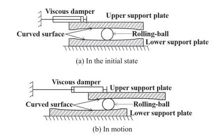
Fig.1 Two typical states of the proposed device
The integration of three groups of rolling balls and curved surfaces is the most significant enhancement over standard friction pendulum systems used in the literature,as three rolling balls can work together to safeguard acceleration-sensitive equipment from seismic damage.If designed properly, all three rolling balls can perform reliably even if individual balls are slipping.Meanwhile,the conical pendulum bearing is not weight dependent.It can prevent rocking, and the gravity restoring force provides recentering of the system.The conical pendulum bearing has no natural period.Resonance is impossible for the system isolated with conical pendulum bearings.Moreover, the components employed in this device are inexpensive and easy to implement, allowing for mass production.Steel support plates permit the efficient connecting of seismically isolated equipment.
The formulation of theoretical motion formulas for the conical pendulum bearing is the first step in this study,which is followed by a detailed discussion of the essential parameter assessments.Prototypes with various surface characteristics are generated and manufactured.The isolation performance of this unique device is verified using shake table tests.The responses to acceleration and displacement are measured and compared.Finally,a numerical model of the isolation system is provided for future research, and the accuracy of the model is demonstrated by the aforementioned tests.
2 Theoretical analyses of the device
2.1 Analytical model of the device
Due to manufacturing and assembly problems, some of the rolling balls in a pendulum bearing with more than three sets of rolling balls and curved surfaces may not be able to fully contact the upper support.As a result,three sets of single pendulum systems are included in the novel suggested device, each of which is designed to behave independently.Meanwhile, these three sets of single pendulum bearings meticulously preserve the horizontal translation of the upper support plate.To further understand the dynamic behavior of this unique pendulum bearing, a simpler analytical model of a single pendulum system is developed first, exploiting the symmetrical arrangements.The ball will continue to roll between the higher and lower support plates (in the pure rolling state) during an earthquake, as seen in Fig.2.
2.2 Restoring force
All of the members in the analytical model are assumed to be rigid bodies, meaning they are unaffected by deformation.The lower support plate is fastened to the ground directly, whilst the higher plate relies on extra connection procedures to keep the equipment or cultural items in place.Given that the ball’s contact with the curved surface is pure rolling, the upper support plate’s(1x,1x˙) and the ball’s (2x,2x˙) displacement and velocity should both be in the same direction.To express this common relationship, the sign-function is used:
As previously stated, the device is constructed using velocity-related type (viscous) dampers, and the typical force-velocity constitutive model is as follows:
whereFcis the damping force,cis the damping coefficient,vis the velocity of the piston, andβis the velocity index.Considering the linear damping, the velocity index is set to one.

Fig.2 Analytical model
To determine the mechanism within the single pendulum system, the analytical model must be divided into three separate balanced bodies.As indicated in Fig.3,M,m1andm2represent the mass of the isolating equipment, the upper plate, and the rollingball, respectively;gis the gravitational acceleration;˙x˙gand ˙z˙gare, respectively, the horizontal and vertical seismic accelerations;1x˙˙ and ˙x2˙ represent the relative horizontal accelerations of the higher plate and the ball, respectively; and1z˙˙ and ˙z2˙ represent the relative vertical accelerations of the upper plate and the ball,respectively.The tangential contact forces between the ball and the upper and lower plates are denoted byT1andT2, respectively.The normal contact forces between the ball and the upper and lower plates are denoted byN1andN2, respectively.Ffrepresents the rolling friction force between the ball and the curved surface;crepresents the damping coefficient;Iis the ball’s inertia moment;αis the ball’s angular acceleration; andθis the tangent contact angle between the ball and the curved surface.
The following equations can be constructed by considering the force and geometry relationships between the three independent components:

Fig.3 Free body diagram

The maximum horizontal absolute acceleration of the upper support plate can be expressed using Eq.(13),as follows:
If the rolling friction force and viscous damping force are ignored, the horizontal restoring force of the upper plate can be calculated as follows:
The horizontal restoring force of the upper plate is dependent on the angleθ, the total mass of the upper plate and the equipment (Mandm1), based on Eq.(23).
The properties of the curved surfaces, i.e.,the geometric relationship between the horizontal displacement of the top platex1and the angleθ, should be established in the following sections after the horizontal restoring force has been computed.
2.3 Surface characteristics
Traditional pendulum bearings have spherical and elliptic surfaces.To make comparisons with the unique conical surface, standard spherical surfaces are provided.The radius of curvature affects the natural period of a pendulum-type bearing.As a result, the surface function and the slope associated with it are chosen as comparison indicators.
2.3.1 Traditional spherical surface
The following are the functions of the spherical surface and the accompanying slope:
where the radius of curvature is denoted byR.According to Eq.(25), as the slope increases, the surface tends to flatten.
2.3.2 Traditional elliptic surface
The following are the functions of the elliptic surface and the corresponding slope:
whereaandbrepresent the ellipse’s major and minor axes, respectively.According to the mathematical theories, the elliptic surface tends to become flatter as the major axis or minor axis increases or decreases.
2.3.3 Conical surface
The following expressions can be used to describe the functions of the conical surface and its related slope:
The conical surface’s function is divided into two components.In the initial phase, the function of the conical surface is the same as that of the spherical surface.When the device’s displacement surpasses the critical displacementdb, the surface transforms into a slope with the same gradient as at the critical displacementdb.There is no question that whendbchanges, the smoothness and maximum gradient of the surface will change as well.Meanwhile, the device’s first period is determined by the conical surface’s initial gradient, which is dictated by the radius of curvatureR.
2.4 Characteristics comparisons between different curved surfaces
Previous sections described the spherical, elliptic,and conical curved surfaces.Assuming the secondorder derivative of the surface function exists, the relationship between the angleθand the displacement of the lower platex2can be derived from the gradient.Then, the relationship between the angleθand top plate displacementx1can be also computed.The first period is set to 2.5 seconds, corresponding to a radius of curvature of 750 mm, to make a valid comparison between the different pendulum bearings.When it comes to the conical surface, special attention should be given to the parameter selection in order to maintain the same restoring force.Meanwhile, two sets of elliptic surfaces are introduced to account for the effect of the limit displacement.The key parameters of the four pendulum bearings are listed in Table 1.In addition, as shown in Fig.4, the geometry and slope of the four pendulum bearings are compared.
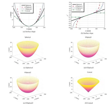
Fig.4 Comparison of geometrical slope and slope of four surfaces

Table 1 Essential characteristics of pendulum bearings(unit: mm)
2.5 Mechanical property of the four pendulum bearings
2.5.1 Stiffness, natural period and horizontal restoring force
The restoring force of the upper plate in the horizontal directionF′ can be reproduced by the variable-stiffness spring if the rolling friction force and viscous damping force are ignored.The stiffness and period of the pendulum bearing can be stated as follows using Eq.(23).
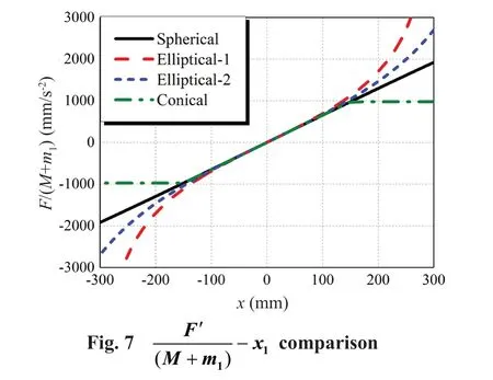
It is important to note that the proposed device’s natural period is unaffected by the overall mass of the separated equipment and upper support plate.The comparisons ofbetween the four pendulum bearings mentioned in Table 1 are shown in Figs.5-7 using Eqs.(30)-(31).
The stiffness and period of the spherical surface remain essentially unchanged asx1grows, as shown in the three comparison charts; however, the horizontal restoring force increases linearly.The stiffness of the elliptic surface rises when the period decreases.The elliptic surface stiffness increases as the period decreases.When the rolling-ball reaches the curved surface’s border, the restoring force of the elliptic surface is identical to that of the spherical surface to some extent,and it changes swiftly.The features of the conical surface are nearly identical to those of the spherical surface when the displacementx1is less thandb.The radius of curvature becomes infinite when the displacementx1exceedsdb, and the horizontal restoring force tends to be fixed.Furthermore, as the period lengthens, the conical surface’s stiffness gradually decreases.
In summary, the stiffness softening mechanism in the proposed conical pendulum bearing reduces stiffness as displacement increases.The conical pendulum bearing,as compared to spherical and elliptic surfaces, has the ability to eliminate unwanted resonance effects caused by low-frequency ground motion amplification.
2.5.2 Hysteretic performance
Note that the influence of rolling friction was ignored in the preceding sections for the purpose of simplicity.Equations (16)-(17) can be rewritten as follows when the rolling frictionFfis taken into account while calculating the horizontal force:


Fig.6 T- x1 comparison
whereμis the rolling friction coefficient.The rolling friction coefficient is normally low, and it can be set to 0.005.Because the sum of the masses of the upper plate and separated equipment (M+m1) is significantly greater than the mass of the rolling ballm2, Eq.(32) has been simplified.The rolling friction is dependent onM,m1andμ,according to Eq.(32).
The theoretical hysteresis curves of the four pendulum bearings (shown in Fig.8) can be derived when the rolling friction force is added to the horizontal force (the viscous damping force is removed).

Fig.8 Comparison of theoretical hysteretic curves
Even when rolling friction is taken into account, the energy dissipation performance of the four pendulum bearings is inadequate, as shown in Fig.8.As a result,more dampers are fitted to improve system damping and energy dissipation.In addition, when the displacements increase, the conical pendulum bearing stiffness decreases and the horizontal restoring force becomes saturated, preventing high shear forces from being transferred.
2.5.3 Self-restoring performance
It is commonly known that after an earthquake, a pendulum bearing with a detailed configuration can return to its original position.The pendulum bearing may create a self-restoring forceFr.due to the dead load and the features of the curved surface.At moderate speeds,the rolling ball can only return to its original place if the self-restoring forceFris greater than the friction forceFf.Because the rolling ball’s velocity is usually low, the viscous damping force can be ignored, and the horizontal and vertical seismic accelerations are zero.
Only if sinθ≥μcan the pendulum bearing return to its original position, according to Eq.(33).Given thatθis usually small, Eq.(33) can be rewritten as tanθ≥μ,i.e.,
Equation (34) can be rewritten byy′(xc)=μif the theoretical maximum residual displacement isxc.As a result, the four pendulum bearings’ theoretical maximum residual displacements are 3.75 mm, 3.75 mm,3.77 mm, and 3.79 mm, respectively.The minimal residual displacements of all four pendulum bearings are fairly small, indicating exceptional self-restoring performance.
3 Shake table tests
As previously stated, the conical pendulum bearings proposed in this study can aid in reducing the peak acceleration response of the equipment.Shake table tests are conducted to determine the seismic performance of the bearings in a variety of configurations.Several techniques are used during the test to handle the excessive displacements caused by long-period ground vibrations, including stiffening system damping, and self-restoring force.The following sections will illustrate these measures in detail.
3.1 Design process of pendulum bearings
3.1.1 Crucial parameters
The initial radius of curvatureRand the critical displacementdb, according to Eq.(28), control the surface function of the conical pendulum bearing.As previously stated, the critical displacementdbdetermines the conical surface’s maximum self-restoring force and smoothness,whereas the parameterRdetermines the initial radius of curvature.There are three more parameters to consider in addition to the velocity-related damping coefficientc.As a result, four sets of conical pendulum bearings have been configured in detail to investigate the impact of the three parameters on the pendulum bearings’ seismic reaction.The precise information for the four conical pendulum bearings is listed in Table 2, with damping taken into consideration when calculating the period.In addition, Fig.9 and Fig.10 show stiffness and period comparisons of the four conical pendulum bearings.
3.1.2 Support plates and curved sphere
Three sets of curved surfaces are consistently distributed throughout the upper and lower support plates, which have a diameter of 300 mm, as shown in Fig.11.The top and lower support plates are both720 mm in diameter.Q345 high-strength steel is used to make the support plate.The depth of the curved surface has also been raised by 5 mm to help with the rolling ball constraint.The maximum depth of the curved surface should be less than 15 mm, according to the conical surface function.As a result, the support plate’s thickness is adjusted to 25 mm to ensure that the narrowest section’s thickness is greater than 5 mm.
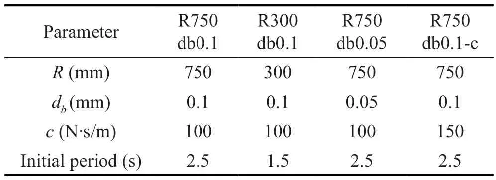
Table 2 Crucial characteristics of conical pendulum bearings
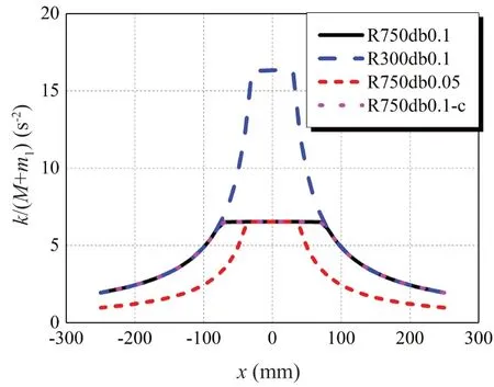
Fig.9 Stiffness comparisons
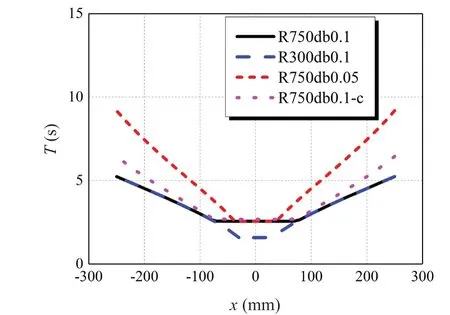
Fig.10 Natural period comparisons
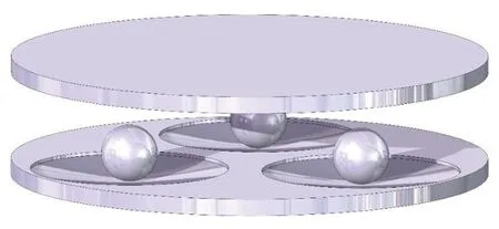
Fig.11 Schematic diagram of the device
Complementary finite element simulation using Ansys software was used to check the strength and deformation capacity of the upper support plate.The device is modelled using Solid45 elements, with equal surface pressure supplied to the upper plate to simulate the weight of the isolated equipment (200 kg).In the meantime, the lower plate is secured to the ground,creating a static boundary condition.The simulated results (see Figs.12-13) show that the upper support plate’s stress and deformation are relatively minor,meeting the performance requirements.
3.1.3 Viscous damper
The energy dissipation capabilities of the pendulum bearing, as previously noted, are insufficient.As a result,the pendulum bearings are equipment with viscous dampers.The rolling-ball design displacement is set to 125 mm, while the top plate design displacement is set to 250 mm, based on the curved surface’s diameter of 300 mm.In the meantime, due to the high diameter and design displacement of the upper plate, a damper system is developed by connecting two sets of bidirectional viscous dampers with a single stroke of 150 mm (see Fig.15) in tandem, rather than a standard 300 mm damper (see Fig.14).
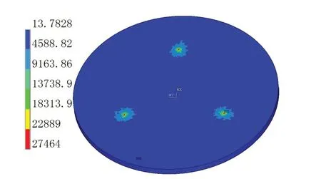
Fig.12 Stress contours (kPa) of upper plate

Fig.13 Deformation contours (mm) of upper plate

Fig.14 Schematic design of single damper
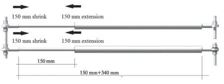
Fig.15 Schematic diagram of damper system
The isolation bearing’s size should be small as possible while still providing adequate performance to permit implementation in actual engineering projects.As a result, the dampers are designed to link the support plate’s center.Fisheye and flat round joints (see Figs.16-17) are used in the connection zones to allow the device to move freely.In the meantime, casing clamps (see Fig.18) are installed to lock the dampers to the upper plate and keep them from colliding with the rolling balls.In addition, the pendulum bearing is fitted with three distinct damping transmission mechanisms to ensure proper damping in all directions (see Fig.16).Rubber gaskets are also used at the damper-to-lower-plate interface to minimize the upper plate's in-plane torsional reaction.Figures 19 to 21 show the damper and support plate layouts in detail.
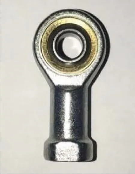
Fig.16 Fisheye joint
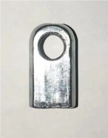
Fig.17 Round and flat joint
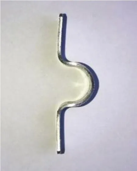
Fig.18 Casing clamp
3.1.4 Rolling ball and rolling friction force
The steel rolling ball measures 85 mm in diameter,and is designed to fit the dampers located between the top and bottom support plates.As shown in Fig.22, the rolling ball’s surface is sanded to keep it from slipping against the curved surface.
Because there is no model that can determine the rolling friction coefficient properly, it is usually calculated indirectly.Liet al.(2017) proposed a method for calculating the rolling friction coefficient exactly utilizing variables easily extracted from standard distance angle measurement devices.Statistical process control (SPC) testing is used to confirm the data’s validity throughout the measurement process.The method’s correctness was also tested using discrete element simulations.
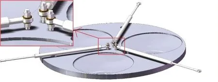
Fig.19 Connection between the damper and the lower support plate

Fig.20 Connection between the damper and the upper support plate
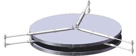
Fig.21 Overall connection diagram

Fig.22 Rolling ball
The rolling friction coefficient is calculated in this work using the method suggested by Liet al.(2017).The lengthL, angleθand height of the inclined planeh1,height of the cabineth2, and horizontal distance between the ball drop point and the cabinetHare all measured throughout the test, as shown in Fig.23(a).Each test should be carried out at least 30 times before the data is standardized.Finally, the rolling friction coefficient can be expressed as follows:
A slope is created using the same material and surface roughness as the isolation bearing to simulate the rolling ball’s surroundings (see Fig.23(b)).The series tests are carried out with a smaller ball of the same material and roughness since the rolling ball in the isolation bearing is too large to directly determine the rolling friction coefficient.The test was repeated 44 times following the aforementioned procedure, and the SPC method was used to determine whether the data was normally distributed using MATLAB software.According to experimental results, the rolling friction coefficient between the ball and the support plates is 0.005.
3.2 Shake table tests
3.2.1 Shake table apparatus
The shake table tests were carried out at the Key Laboratory of Earthquake Engineering and Engineering Vibration of the China Earthquake Administration.The shake table used in this test (see Fig.24) has a table size of 3.5 m by 3.5 m with a maximum horizontal and vertical displacement of 0.025 m and 0.02 m, respectively.Horizontal and vertical top speeds are 2.4 and 1.8 m/s,respectively.Meanwhile, maximal accelerations in the longitudinal, transverse, and vertical directions are 4 g,4 g, and 3 g, respectively.It has a payload capacity of 60 kN and a maximum overturning moment of 400 kN·m.This facility’s parameters are presented in detail by Ninget al.(2017).The configuration of the test models on the shake table is shown in Fig.25.
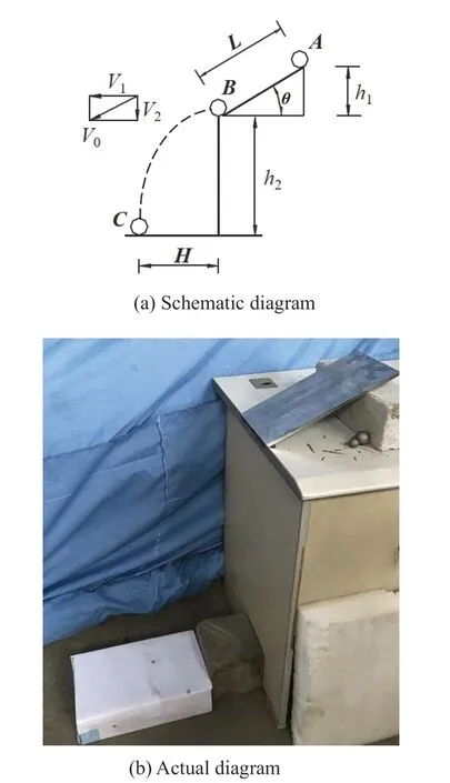
Fig.23 Actual rolling friction coefficient measurement
3.2.2 Arrangement of sensors
Two different types of sensors, including accelerometers and displacement transducers, were put on the model to assess the pendulum bearing’s isolation efficiency.The isolation efficiency of a pendulum bearing is as follows:
The natural period of the proposed device is independent of the total mass of the separated equipment and top support plate, according to Eqs.(30) to (31).Meanwhile, the equipment is frequently attached to the higher plate, resulting in the isolated equipment and the upper plate experiencing equal acceleration reactions.As a result, for the sake of simplicity, the equipment model was not fitted individually throughout the test.The seismic reactions of the higher plate are used in this scenario to conduct the following investigation.
There were five piezoelectric acceleration sensors in all, one included inside the laboratory shake table system and four external acceleration sensors used to monitor the pendulum bearings’ acceleration responses(see Fig.26).The acceleration sensors were attached to the shaking table and the upper support plates of the shake table.Meanwhile, the trajectory of the isolated equipment’s center was studied using 12 drawing displacement sensors with ranges of ±200 mm.The distributions of multiple accelerometers and drawing displacement sensors are shown in Fig.27.

Fig.24 Shake table
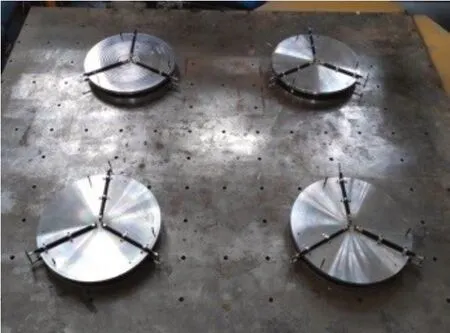
Fig.25 Layout of test models
3.2.3 Input ground motion records
To test the device’s isolation efficiency, three distinct types of ground motions were used as input accelerations: (a) short-period (high-frequency) ground motions, (b) intermediate-frequency ground motions,and (c) long-period (low-frequency) ground motions.The main ground motion frequencies are used to classify these three ground motions.Table 3 shows the ground motions in detail.Meanwhile, time histories,acceleration frequency spectrums, and acceleration,velocity, and displacement response spectrums are shown in Figs.28 to 32 (damping 5%).As illustrated in Fig.29,high-frequency ground motion has a predominant frequency larger than 1.5 Hz, intermediate-frequency ground motion has a predominant frequency roughly between 1 Hz and 1.5 Hz, and low-frequency ground motion has a predominant frequency less than 1.0 Hz.
According to the Chinese Code for Seismic Design of Buildings (GB 50011-2010, 2010), shake table tests were conducted using three-dimensional inputs and a PGA ratio of 1: 0.85: 0.65 for the major direction (xaxis in Fig.26) to the other two directions.Based on a seismic intensity of 8(9), the peak accelerations (PGAs)associated with minor, moderate, and large earthquakes were calculated to be 0.07 g (0.14 g), 0.2 g (0.4 g), and 0.4 g (0.62 g), respectively.To test isolation performance under extreme situations, a severe earthquake with a PGA of 1.0 g was used.Meanwhile, white noise stimulation experiments were conducted to determine the specimens’ dynamic properties.During the testing,a total of 42 instances were conducted, and Table 4 summarizes the inputs used in each test.

Table 3 Detailed information of input ground motions
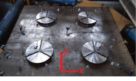
Fig.26 General arrangement of measuring points
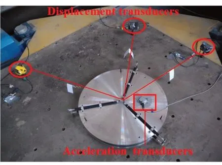
Fig.27 Precise location of measurement points
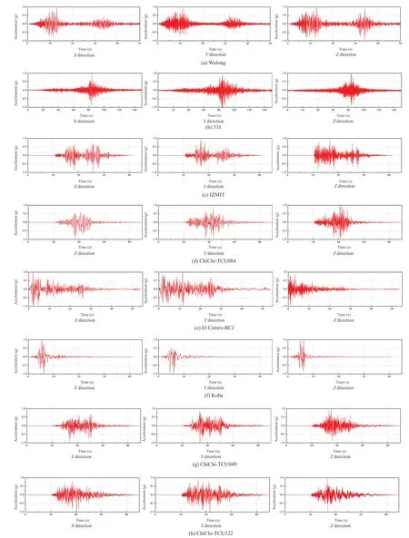
Fig.28 Time histories of input ground motions

Fig.28 Continued

Fig.29 Frequency spectrums of input accelerations
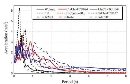
Fig.30 Response spectrums of input accelerations
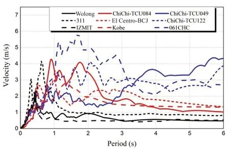
Fig.31 Response spectrums of input velocities
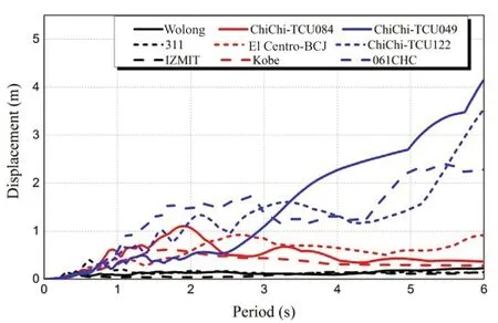
Fig.32 Response spectrums of input displacements
3.3 Shake table test results
3.3.1 Test phenomenon
The upper support plate was swaying at the start of the test due to the vibration noise from the shaking table facility.Meanwhile, as the PGA expanded, the upper support plate’s displacement responses became more obvious (see Fig.33 to Fig.35).Furthermore,the displacement response of the top support plate rose when the major frequency of the ground vibrations decreased while maintaining a constant PGA.There was no overturning or twisting during the test while the pendulum bearing was within the specified displacement threshold.As a result, the damper system proposed in the previous sections adequately addressed the damper travel issue.
The rolling-ball could almost completely recover to its original position after each test, while the pendulum bearings demonstrated an amazing ability for self-restoration after each test.Several rolling-balls,however, were unable to entirely return to their former places in a few instances due to a severe displacement response.The phenomenon could be explained by the rolling-ball slipping on the curved surface.Furthermore,if the support plates are unable to be positioned due to significant manufacturing flaws, the ball will move easily around the curved surface.
3.3.2 Acceleration responses of the devices
Because the shaking table did not respond accurately to the input accelerations, the accelerations measured by the acceleration sensor attached to the shake table were used as input accelerations.The effects of three elements on acceleration isolation efficiency will be investigated in the following sections, based on these data: (1) ground motions, (2) damping parameters, and (3) surface function parameters.Due to the limited amount of space available, only a few common tests will be described in depth.
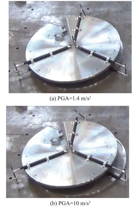
Fig.33 Maximum displacement response of the same device under 311 ground motion for various PGAs
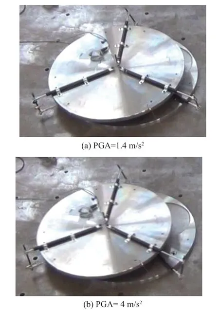
Fig.34 Maximum displacement response of the same deviceunder ChiChi-TCU084 ground motion for various PGAs
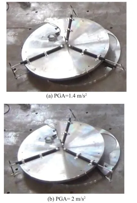
Fig.35 Maximum displacement response of the same device under 061CHC ground motion for various PGAs
The horizontal accelerations in Fig.36 are compared between equipment with and without R300db0.1 bearing when subjected to three high-frequency ground motions(Wolong, 311, and IZIMIT) at PGAs of 0.7 m/s2and 10 m/s2.When the PGA is set to 0.7 m/s2, the device’s maximum acceleration response in thexdirection is reduced by 66%, 60%, and 64%, respectively, while the acceleration response in theydirection is reduced by 67%, 57%, and 56%, respectively; when the PGA is set to 10 m/s2, the device’s maximum acceleration response in thexdirection is reduced by 74%, 71%,and 85%, respectively, while the acceleration response in theydirection is lowered by 76%, 61%, and 75%,respectively.As a result, conical pendulum bearings have better isolation performance when subjected to highfrequency ground motions, and the isolation efficiency improves as the PGA increases.
When equipment with and without R300db0.1 bearings is subjected to three intermediate-frequency ground motions at PGAs of 0.7 m/s2and 4 m/s2, the horizontal accelerations are shown in Fig.37.When the PGA is set to 0.7 m/s2, the maximum acceleration response of the device in thexdirection when subjected to ChiChi-TCU084, El Centro-BCJ, and Kobe ground motions decreases by 21%, 37%, and 20%, respectively,while the acceleration response in theydirection decreases by 20%, 21%, and 23%, respectively;when the PGA is set to 4 m/s2, the device’s maximum acceleration response in thexdirection is reduced by 68%, 45%, and 38%, respectively, while the acceleration response in theydirection is reduced by 34%, 33%, and 30%, respectively, when subjected to ChiChi-TCU084,El Centro-BCJ, and Kobe ground motions.As a result,it can be concluded that conical pendulum bearings provide adequate isolation against intermediatefrequency ground vibrations, with the isolation efficiency increasing as the PGA increases.
Figure 38 shows the horizontal accelerations of equipment with and without R300db0.1 isolation when subjected to three low-frequency ground motions with PGA of 0.7 m/s2and 2 m/s2.It can be seen that when the PGA is set to 0.7 m/s2, the maximum acceleration of the device in thexdirection subjected to ChiChi-TCU049,ChiChi-TCU122, and 061CHC ground motions decreases by 46%, 41%, and 7%, respectively, while the acceleration response in theydirection decreases by 42%, 41%, and 10%, respectively; when the PGA is set to 2 m/s2, the device’s maximum acceleration response in thexdirection is reduced by 37%, 38%, and 8%, respectively, when subjected to ChiChi-TCU049,ChiChi-TCU122, and 061CHC ground motions, while the acceleration response in theydirection is reduced by 60%, 51%, and 14%, respectively.As a result, the conical pendulum bearings operate satisfactorily in the presence of low-frequency ground motions, and their isolation efficiency nearly keeps constant as the PGA grows.
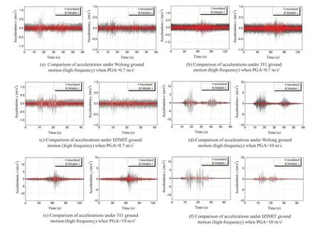
Fig.36 Comparisonofaccelerations betweentheequipmentwithR300db0.1 bearing and without isolation subjected to three highfrequencyground motionswith PGAof0.7m/s2 and10 m/s2

Fig.37 Comparisons of accelerations between the equipment with R300db0.1 bearing and without isolation subjected to three intermediate-frequency ground motions with PGA of 0.7 m/s2 and 4 m/s2
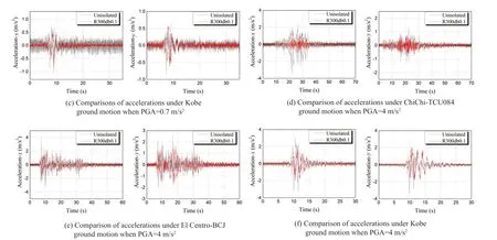
Fig.37 Continued

Fig.38 Comparison of accelerations between equipment with R300db0.1 bearing and without isolation subjected to three low-frequency ground motions with PGA of 0.7 m/s2 and 2 m/s2
As the frequency of ground motion rises, the R300db0.1 bearing becomes more efficient in terms of PGA decline.When subjected to the 061CHC ground motion, the R300db0.1 bearing exhibits poor isolation performance, which can be attributed to: (a) the steep slope and considerable displacement causing sliding between the rolling-ball and the curved surface; and (b)the R300db0.1 device’s frequency near to the 061CHC ground motion.
In addition, certain sample ground motions are chosen to assess the impact of surface features and additional damping on the acceleration response.Figures 39 to 42 demonstrate the maximum acceleration responses of the four conical pendulum bearings and the shaking table with varied PGAs when subjected to Wolong, El Centro-BCJ, ChiChi-TCU122, and 061CHC ground movements.As previously stated, two parameters define the surface of the conical pendulum bearing:Randdb.The R750db0.1 bearing outperforms the R300db0.1 bearing under high-frequency ground motions, whereas the R750db0.1 bearing outperforms the R300db0.1 bearing under intermediate-frequency and low-frequency ground motions, especially as the PGA rises.When comparing the isolation efficiency of the R750db0.1 and R750db0.05 bearings in terms ofdb,it is clear thatdbhas no influence.
The influence of the damping parametercis further investigated by comparing the R750db0.1 and R750db0.1-c pendulum bearings.Both devices have excellent isolation performance under high-frequency ground vibrations, and there is no obvious difference between them.For medium and low-frequency ground motions, the R750db0.1 bearing outperforms the R750db0.1-c bearing with the development of the PGA.Table 5 displays the isolation efficiency of conical pendulum bearings in a range of test circumstances.
There are always some high-frequency sounds present in the shake table and specimen acceleration responses,as shown in Figs.39 to 42.The maximum acceleration responses of the shake table and the specimens may notbe accurately recovered when the acceleration input is small because of the high-frequency noise coverage,resulting in little variance between the four conical pendulum bearings.The reasons for the high-frequency hits are as follows: (a) point-surface contact between the rolling ball and the curved surface; (b) misalignment of the support plate due to installation issues or rollingball sliding during the test; and (c) viscous dampers with unstable energy dissipation performance at low acceleration input levels.
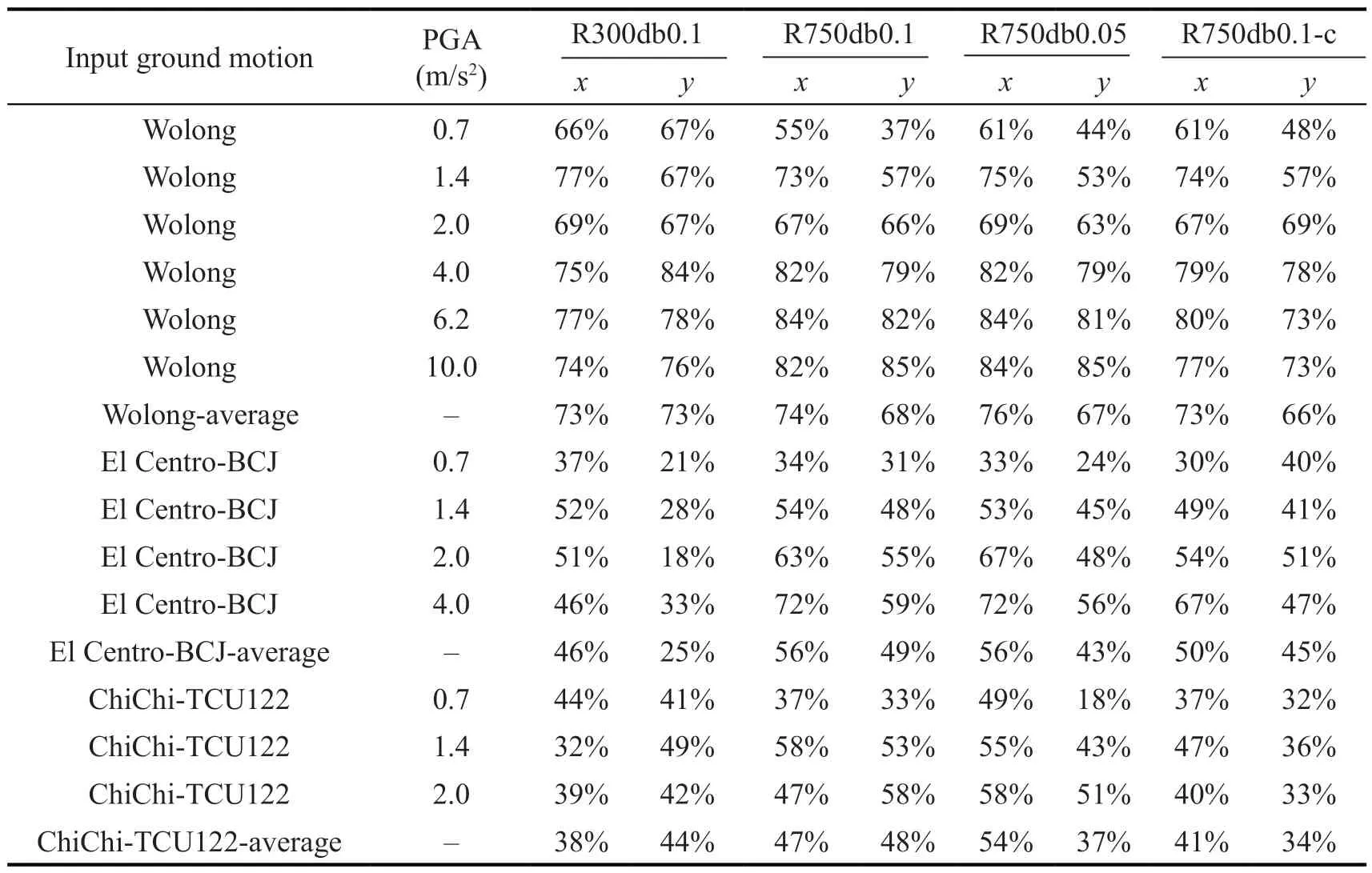
Table 5 Isolation effectiveness of conical bearing in a number of illustrative tests

Fig.39 Maximum acceleration responses and isolating effectiveness during Wolong (high-frequency) ground motion

Fig.40 Maximum acceleration responses and isolating effectiveness during El Centro-BCJ (medium-frequency) ground motion

Fig.41 Maximum acceleration responses and isolation efficiency during ChiChi-TCU122 (low-frequency) ground motion

Fig.42 Maximum acceleration responses and isolation efficiency during 061CHC (low-frequency) ground motion
3.3.3 Displacement responses of the devices
The displacement gauge data can be used to determine the relative displacement responses of pendulum bearings.The impact of the ground motions, the damping coefficient, and the surface function parameters on the isolation efficiency can then be assessed using the relative displacement responses.
The two-horizontal relative-displacement responses and the movement locus are shown in Figs.43 to 46 when the R750db0.1 bearing is subjected to Wolong (highfrequency), ChiChi-TCU084 (intermediate-frequency),ChiChi-TCU122, and 061CHC (low-frequency) with PGA of 2 m/s2.As the primary frequency of the ground motions rises, the relative displacement amplitudes decrease.The outstanding self-restoring abilities of the R750db0.1 bearing are further supported by the displacement responses, which show virtually little residual displacement.
The four conical pendulum bearings’ maximum relative displacement responses (in thexdirection)to Wolong, ChiChi-TCU084, ChiChi-TCU122, and 061CHC ground movements with varied PGAs are shown in Figs.47 to 50.It is found that the R300db0.1 bearing has a significant displacement, which might be the result of sliding between the rolling ball and the curved surface.In addition, the maximum displacement response can be lowered by appropriately increasing the damping coefficient.However, the maximum displacement responses of the conical pendulum bearings will not noticeably differ whether the parameterR/dbis set to 0.1 or 0.05.
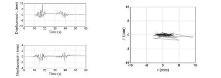
Fig.43 Relative-displacements and movement locus of the R750db0.1 bearing under Wolong (high frequency) ground motion when PGA=2 m/s2

Fig.44 Relative-displacements and movement locus of the R750db0.1 bearing under ChiChi-TCU084 (intermediate frequency)ground motion when PGA=2 m/s2
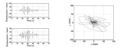
Fig.45 Relative-displacements and movement locus of the R750db0.1 bearing under ChiChi-TCU122 (low frequency) ground motion when PGA=2 m/s2
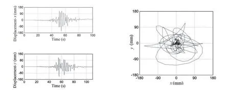
Fig.46 Relative-displacements and movement locus of the R750db0.1 bearing under 061CHC (low frequency) ground motion when PGA=2 m/s2

Fig.47 Maximum relative-displacements under Wolong(high-frequency) ground motion
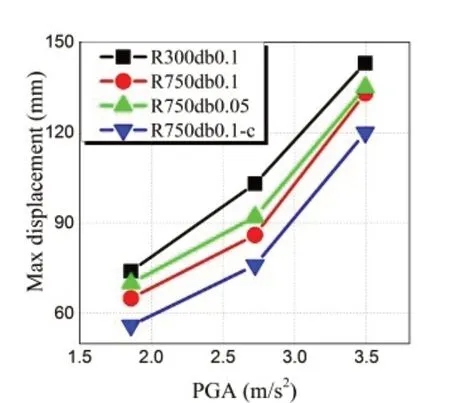
Fig.48 Maximum relative-displacements under ChiChi-TCU084 (intermediate-frequency) ground motion
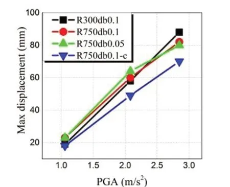
Fig.49 Maximum relative-displacements under ChiChi-TCU122 (low-frequency) ground motion
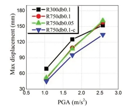
Fig.50 Maximum relative-displacements under 061CHC(low-frequency) ground motion
4 Numerical analysis
Shake table tests cannot be performed in every situation.Tests are a great addition to numerical analysis.When working with complex models, universal finite element tools like Ansys and Abaqus can be time-consuming.For future study, a MATLAB-based numerical model of the isolation system is suggested.Equation (22) states that the supplied variables can be used to directly compute the upper plate’s relative acceleration response1x˙˙.Numerical integration can be used to determine the top plate’s relative velocity and displacement (1x˙,1x) once has been established.Note that the relative velocity1x˙˙ and the tangent contact angleθchange as the device moves rather than staying the same.Thus, the following can be used to rewrite Eq.(22):
The device is taken to be at rest prior to the earthquake.Once the upper plate is moving, Eq.(34)will always hold true, making it possible to calculate the differential Eq.(37) numerically.The first order Runge-Kutta-method (Euler-method), Newmark’s-βmethod, and the method of central differences are just a few of the numerical techniques available for resolving the initial value problems of differential equations.In this study, the differential Eq.(37) is solved using Newmark’s-βapproach.Assume that the top plate’s relative displacementxt, velocitytx˙, and accelerationtx˙˙ at timetiare all known.
With the aid of the parametersβandγ,which control how the time integration behaves, it is possible to calculate the displacementxt+1, velocityx˙t1+, and acceleration ˙x˙t1+atti+1using Newmark’s-βmethod.
Iftxis known,θtcan be found by the surface function.
In addition, special attention should be given to the moment the upper plate starts to move.The relative displacementxtand relative velocitytx˙ of the upper plate at timetimust both be zero, and the horizontal seismic acceleration ˙x˙g,tmust be smaller thanμg, for the upper plate to remain at rest in the initial condition.If the higher plate is motionless for a brief length of time,the relative acceleration and velocity of the top plate at the subsequent instant should be zero, and the relative displacement should be constant.
After the upper plate starts to move, the time period should be divided into two parts: during the first part,the upper plate remains stationary, and during the second part, it keeps moving.A fake relative acceleration ˙x˙t,pat timetiand a real relative acceleration ˙x˙t+1can be roughly expressed in terms ofx˙g,tandx˙g,t+1, respectively,according to Eq.(37).Negative numbers make up the product of ˙x˙t,pand ˙x˙t1+.Assume that the relative acceleration varies linearly across the time period in order to pinpoint the precise time at which ˙x˙1,s= 0,or the start timets.The numerical integration can be finished by changingtstotibecause the device’s initial state and the state attiare consistent.
The upper plate’s relative velocity must at some point be zero if the top plate changes from motion to stillness.The upper plate will stop moving if its relative acceleration ˙x˙g,tis less thanμgduring the transition interval; otherwise, it will keep moving.In this case,the relative velocity’s sign affects the damping force,which changes the damping force.It’s important to remember that the damping force should remain consistent throughout the brief period.At the start of each integration step, the damping force is added to the motion equation; it then stays there throughout the step.The equation of motion stays constant during this integration step even if the damping force’s sign changes over this time period.At the following integration stage,the actual damping force can then be ascertained.
In light of this, it is crucial to identify the time instant at which the relative velocity of the upper plate is zero.The following formula can be used to compute this special time instantt+tδ:
Meanwhile, the relative displacement of the top plate and the ground motionxt tδ+can be written as follows:
Considering the relative velocity of the top plate att+tδis zero, the starting values of the relative acceleration ˙x˙t tδ+can be obtained by the equation of motion, written as follows:
Hence, given thatxt tδ+is known,θt tδ+may be determined using the surface function.The numerical integration can be finished by changingtiwitht+tδafter calculating (xt tδ+,x˙t tδ+, ˙x˙t tδ+).
With the flow chart shown in Fig.51, the entire numerical analysis can be summed up as follows given the prior explanation.
(1) The known solution dependent variables, such as,tx,tx˙,tx˙˙can be read from the previous step at the start of the integration, whereasx˙˙g,t, ˙z˙g,tcan be read from the input accelerations.The surface function states thatθtcan be expressed in terms oftx.The damping force can be updated in terms oftx˙ in the interim.
(2) The relative acceleration ˙x˙t1+can be updated using Eq.(37).The motion status of the upper plate should now receive specific attention.This integration phase will be completed withandwhen the top plate is at rest.
(3) When the top plate begins to move, the solution dependent variables (xt+1,x˙t1+) can be solved by employing the fake relative acceleration ˙x˙t,pTo determine whether the product oftx˙ andx˙t+1is positive or negative in this situation, extra judgment is needed.This integration stage will be finished right away if the outcome is positive.Equations (42) to (45) should be used to identify the solution dependent variables, such asxt1+,x˙t1+, ˙x˙t+1, if the product is negative.
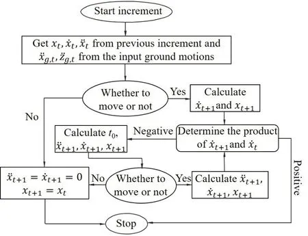
Fig.51 Numerical analysis flow chat
(4) The motion condition of the top plate should be reconfirmed after determining the product oftx˙ andx˙t1+.This integration phase will be finished withif the upper plate is stationary, andxt+1is compatible with the relative displacement determined in Step (3).The product oftx˙ andx˙t+1determined in Step (3) needs to be recalculated if the upper plate keeps moving.The procedure that follows adheres to Step (3).
(5) Repeat the previous steps until the numerical analysis is finished.
The numerical analysis is done using MATLAB techniques.Each conical pendulum bearing was tested 42 times on the shake table.Only a few typical ground motions are chosen as input accelerations to compare with the experimental data, due to the space limitations,the R750db0.1 bearing is used for the comparisons.To precisely reflect experimental circumstances, the seismic acceleration recorded from the shaking table is applied in the numerical analysis.The damping coefficient is set to 110 N·s/m, and the rolling friction coefficient is set to 0.005 (see Section 3.1.4).Table 6 also contains the bearing’s parameters, which were employed in the simulation.
The comparisons of the R750db0.1 bearing’s actual and simulated performance under three different ground motions with various PGAs are depicted in Figs.52 to 54.As can be observed, the simulated results for the top plate movement locus, relative acceleration responses,and relative displacement responses are comparable to the test results.The comparative findings show that the test results can be trusted and that the simulated outcomes are effective.
The R750db0.1 bearing’s experimental and simulated performance under three different ground motions with various PGAs are compared in Tables 7 to 9.The objects of comparisons are between the recorded peak displacements or peak accelerations in two directions and the simulated results at the samemoment.The simulated peak acceleration responses and peak displacement responses are very close to the test results.The comparison results verify the accuracy of the simulated results as well as the reliability of test results, both of which can be applied to further research.

Table 6 Conical pendulum bearing specifications: R750db0.1

Table 7 Comparison between experimental and simulated results of R750db0.1 bearing under Wolong ground motion (high-frequency) with PGA of 6.2 m/s2

Fig.52 Comparisonbetween experimental and simulated results of the R750db0.1 bearing during Wolong ground motion (high frequency) with PGA of 6.2 m/s2
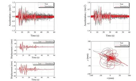
Fig.53 Comparison between experimental and simulated results of the R750db0.1 bearing during El Centro-BCJ ground motion(medium frequency) with PGA of 4 m/s2

Fig.54Comparison between experimentaland simulated results of the R750db0.1 bearing during ChiChi-TCU122 ground motion(lowfrequency) with PGA of2 m/s2

Table 9 Comparison between experimental and simulated results of R750db0.1 bearing under ChiChi-TCU122 ground motion (low-frequency) with PGA of 2 m/s2
5 Conclusions
A new type of conical pendulum bearing is introduced herein that is appropriate for use in electronics or other equipment that is sensitive to acceleration.To examine the dynamic properties, intricate arrangements and related theoretical calculations are made.The four proposed devices were tested on a shake table utilizing a variety of surface properties.Various ground motions, such as short-period (high-frequency), intermediate-frequency,and long-period, are employed (low-frequency).Small, moderate, and large earthquakes in areas with basic seismic intensity degrees of 8 or greater (9) are represented by the accompanying PGAs, which are set at three different levels.For further study, a complementary numerical model of the proposed isolation mechanism is recommended.In-depth research is also carried out to determine how different types of ground motion, surface characteristics, and damping factors affect the devices’acceleration and relative displacement responses.The following conclusions are obtained:
(1) While the maximum relative-displacement responses show a clear inverse relationship, the isolation efficiency of the isolation bearings decreases as the predominant frequency of the ground motions increases.The maximum relative-displacements of the R750db0.1 bearing are approximately 8 mm, 60 mm, and 90 mm,when subjected to low, intermediate, and high frequency ground motions, respectively.With the increase in input peak ground accelerations, the suggested devices display more noticeable isolation performance.
(2) While there is no discernible difference between the R750db0.1 and R750db0.1-c bearings under highfrequency ground motions, the R750db0.1 bearing becomes more efficient than the R750db0.1-c bearing with the increase of the PGA, whereas the maximum displacement responses demonstrate that increasing the isolation system damping could reduce the maximum displacement responses of the device at the expense of isolation efficiency.
(3) The performance of the isolation is obviously impacted by changes in the surface properties.In reality, increasing the parameterRenhances isolation effectiveness but has little impact on thedb/Rratio.
(4) Complementary numerical algorithms for the novel isolation system are proposed, and the simulated peak acceleration responses, peak displacement responses, and peak response times are nearly consistent with test results: under different ground motions, the differences between the peak displacement responses are within 17%, while the differences of the peak acceleration responses are within 20%.The comparison results demonstrate both the value of the simulated results for use in future study as well as the dependability of the test results.
杂志排行
Earthquake Engineering and Engineering Vibration的其它文章
- Reliability-based life-cycle cost seismic design optimization of coastal bridge piers with nonuniform corrosion using different materials
- Finite element model updating for structural damage detection using transmissibility data
- Experimental study on seismic reinforcement of bridge foundation on silty clay landslide with inclined interlayer
- A novel mitigation measure for normal fault-induced deformations on pile-raft systems
- Longitudinal vibration characteristics of a tapered pipe pile considering the vertical support of surrounding soil and construction disturbance
- Resilient performance of self-centering hybrid rocking walls with curved interface under pseudo-static loading
