Failure analysis of the needle valve body of R18CrNi8 steel
2024-01-11,
,
Research Institute,Baoshan Iron &Steel Co.,Ltd.,Shanghai 201999,China
Abstract:A needle valve is a key component of a diesel injector.The needle valve body of the diesel engine,made of R18CrNi8 steel,cracked and failed during the working process.The cracking failure reasons for the carburized injector valve body through chemical composition analysis,metallographic examination,scanning electron microscope(SEM) analysis,and energy spectrum analysis,were investigated.The results reveal that the original material of the needle valve is in conformity with the manufacturing requirement.Due to the high carburizing quenching temperature,the best carburized layer structure was not obtained,and the machining defect from which the crack emanated was not identified.The cracks expanded and eventually led to fracture under the action of altered stress and the high-temperature combustion environment during the operation of the engine.
Key words:injector valve body; failure analysis; R18CrNi8 steel
1 Introduction
The diesel injection system is the heart of a diesel engine,comprising a needle valve and a needle valve body.The main function of this system is to spray the fuel needed for combustion into the combustion chamber after forming a good spray through the injector at a certain time interval,pressure,and oil supply speed according to the working condition of the diesel engine[1].There-fore,the nozzle plays a vital role in the combustion process of diesel engine fuel,such as oil atomiza-tion,heating,evaporation,diffusion,oil and gas mixing,ignition,combustion,heat release,carbon smoke,the formation of harmful components of exhaust gas,and the intensity of combustion excitation wave and noise[2].The needle valve body is a key component of the nozzle that works under extremely harsh conditions,such as high temper-ature,high pressure,impact,and corrosion,for a long duration and requires the needle valve body to have sufficient strength,stiffness,high wear resis-tance,contact fatigue performance,good tempering stability (tempering softening resistance,300-400 ℃),and certain high-temperature corrosion resistance[3-4].Simultaneously,the design and the heat treatment technology of the needle valve body material also require extremely high standards.
The brand of needle valve body steel mainly inclu-des 18Cr2Ni4WA,18CrNi4WA,18CrNi8,and R18CrNi8 to adapt to different types of engines and meet the requirements for different national emission stan-dards[5].According to the requirements of the current national Ⅳ and national Ⅴ emission standards for motor vehicle pollutants,the present working pressure on the needle valve body is more than 160 MPa[6].Therefore,the steel used for the needle valve body needs to undergo carburizing heat treatment to obtain a surface layer with increased hardness and an inner layer of low carbon toughness to meet the perfor-mance requirements of the steel under the working conditions[5].However,the failure of the needle valve body is inevitable due to poor working conditions.
Failure analysis of the needle valve body for a certain type of nozzle is conducted in this paper.The transverse fracture of the needle body occurs during the working process of a diesel engine,and the needle valve body that failed was made of R18CrNi8 steel.The processing flow of the needle valve body is as follows:bar cutting→processing of the internal and external cavity surfaces→carburi-zing→quenching→cryogenic aging treatment→tem-pering→super finishing of the internal and external sealing surfaces.A transverse fracture occurred when the needle valve body was operated,and this fracture was observed at the small shoulder surface of the needle valve body.The crack was transversely pen-etrated along the needle valve body,and the fracture surface was flush and perpendicular to the axial diameter.The macromorphology of the sample is shown in Fig.1.This paper performed a series of tests and introduced the corresponding improvement measures to determine the cause of the needle valve body failure and avoid similar accidents.

Fig.1 Macrographs of the failed needle valve body
2 Research objects and research methods
The chemical composition of the fracture failure sample was determined by inductively coupled plasma emission spectrometry.The fracture morph-ology of the fracture samples was observed and analyzed by a type and scanning electron micro-scopes.The samples were cut lengthwise along the center line,and the inner wall of the failed needle valve body was analyzed under a microscope.The metallographic sample was polished with #180 to #1 200 sandpaper from coarse to fine,polished using 2.5 pm diamond abrasive paste,and etched with 4% (volume fraction) nitrate alcohol solution.After-ward,the surface and core of the sample were an-alyzed by a metallographic microscope.
3 Results and analysis
3.1 Chemical composition and nonmetallic inclu-sion
Chemical composition analysis was carried out on the failed needle valve body sample,and the results are shown in Table 1.The chemical composition results show that all element content of the failed needle valve body is within the range of the R18CrNi8 steel standard composition requirements.

Table 1 Chemical composition of the failed injector valve body made of steel Unit:%
The sample was cut along the longitudinal path,and the metallographic sample was prepared for inclusion analysis.The nonmetallic inclusions in steel were rated in accordance with the national standard GB/T 10561,“Steel-Determination of content of nonmetallic inclusions-Micrographic method using standards diagrams”,and the results are shown in Table 2.The results indicate that the severity levels of A (thin series),D,and Ds in steel are grade 0.5,and other nonmetallic inclusion types are grade 0,meeting the requirements of the needle valve body steel.
The chemical composition and inclusion analysis result of the failed sample show that the steel specifications of the failed needle valve body meet the requirements for manufacturing the needle valve body.

Table 2 Nonmetallic inclusion results of failed injector valve body made of steel
3.2 Fracture morphology analysis
The fracture surface of the failed needle valve body was observed under a microscope,and the macromor-phological characteristics of the fracture surface were analyzed.The results are shown in Fig.2.According to the radiation region,shear lip,and fracture morphology of the fracture surface,the fracture source region is located in the raised region of the fracture surface,as indicated by the arrows in Fig.2(b).Simultaneously,traces of overheating were observed on the fracture surface.The fracture surface was analyzed using a scanning electron microscope to determine the fracture pattern.Analysis results reveal that the fracture is dark gray and the crack expands along the grain boundary,which is a typical characteristic of intergranular fracture.Zooming in on the blue area of the fracture surface,Figs.2(c) and (d) show the presence of several white oxidation spots on the surface of this area,which are traces of heating oxidation,proving the overheating of the fracture surface.
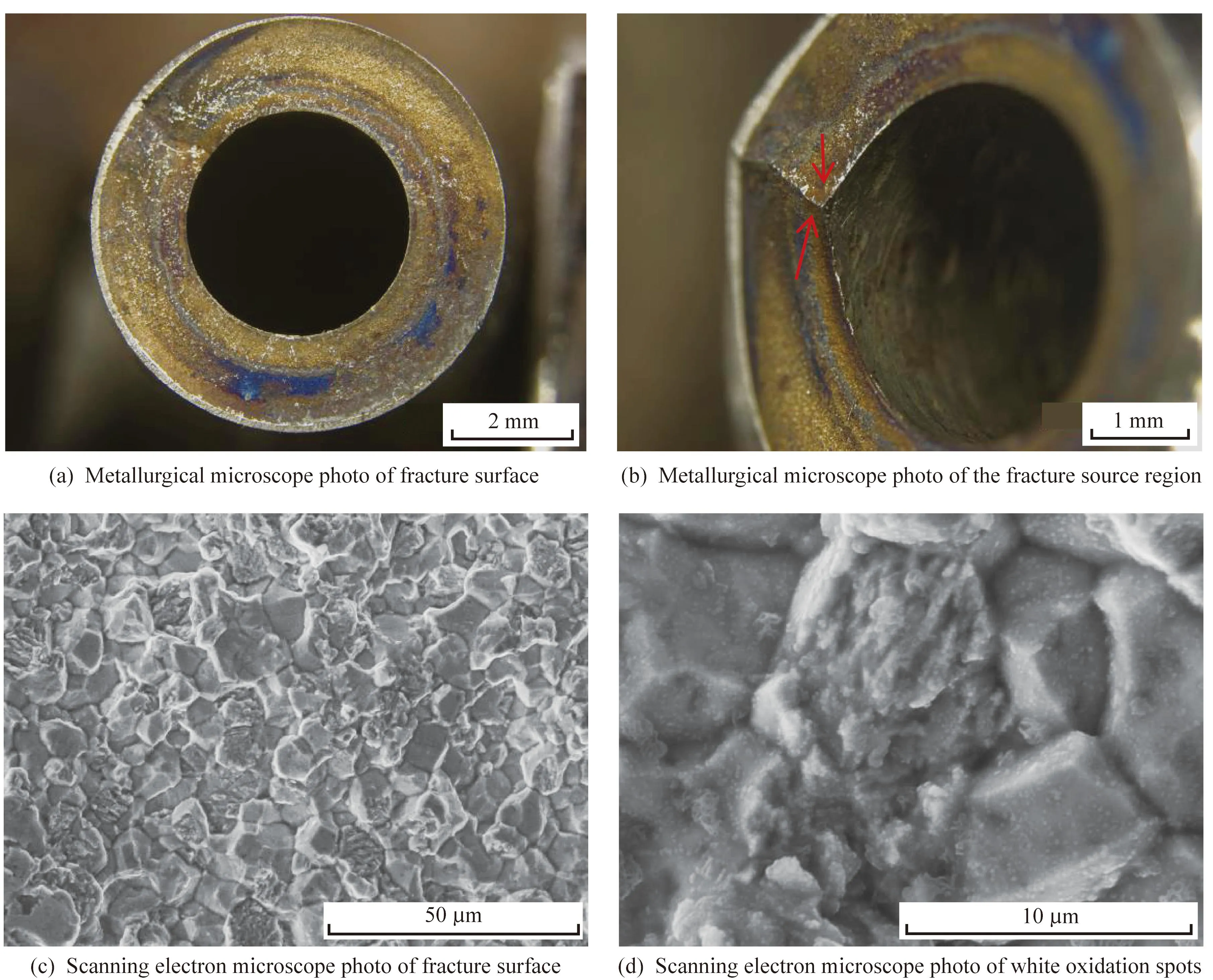
Fig.2 Fracture micrographs of the crack extending area in the needle valve body
The area indicated by arrows in Fig.2(b) demon-strates the considerably rough inner wall of the crack source and several uneven areas.Both parts of the failed needle valve body were opened longitudinally to further analyze the relationship between this region and the causes of cracking,and the micro-scope results are shown in Fig.3.This figure demon-strates the considerably rough inner wall of the needle valve body,with numerous areas revealing fish-scale damage,several pits,and local plastic deformation,as well as rough marks of machining with a depth of 1-2 mm.The inner wall of the needle valve body must be repeatedly rubbed with the needle valve and diesel oil during needle valve operation;thus,the inner wall is regarded as a working surface.Therefore,local damage,such as pitting or machining marks,can easily cause stress concentration on the inner surface of the needle valve body.In addition,Fig.1(b) shows the occur-rence of transverse fracture on the small shoulder surface of the needle valve body,which is an area of stress concentration due to the outer diameter reduction of the needle valve body in this area.The crack propagation morphology of the fracture surface indicated that the crack originated from the inner wall of the needle valve body and then cracked along the small shoulder surface of the needle valve body.This crack then expanded along the wall of the needle valve body,finally forming a transverse fracture.
The insides of the pits were observed by scanning electron microscopy to confirm the cause of inner wall pits,as shown in Fig.3.The inner surface of the pit is remarkably rough,and corrosion traces could be observed.The corrosion trace was con-firmed to be iron oxide by energy spectrum analysis.The working environment of the needle valve is considerably harsh,and the needle valve body has been eroded in the fuel for a long time,with a working pressure of 160 MPa and a tem-perature of approximately 200 ℃.The change in fluid pressure causes the fluid microjet to impact the inner surface of the needle valve body.This repeated impact pressure causes wavy plastic deformation and pitting on the surface of the failed parts,leading to cavitation erosion damage to the inner wall[6].When the local pressure of the fuel reaches a certain level,cavitation tends to occur in a rapidly flowing or vibrating liquid.Bubbles collapse and cause an explosive impact on the surface when they encounter high-pressure areas.These impacts will cause local deformation and pitting of the needle body surface,which eventually coalesce to roughen the surface and cause material loss.The process of material loss is called cavitation erosion,and the resulting damage is referred to as cavitation damage[7-8].Fig.3(a) shows that cavitation damage mainly occurs at the intersection of the inner holes of the needle valve body,where fuel is prone to accumulate and accelerate material corrosion.Addi-tionally,Fig.3 shows numerous blue overheating marks on the inner wall.The main reason lies in the mechanical vibration and repeated temperature changes of the needle valve body when the injector injects the high-pressure fuel supplied by the injection pump into the combustion chamber,affecting the free contraction and expansion of the needle valve body.The temperature gradient and cyclic stress are generated inside the needle valve body,resulting in thermal stress inside the material.Under the alternating load of temperature and mech-anical vibration,stress concentration occurs in the inner wall of the defect area,leading to the germin-ation of cracks at the stress concentration area and propagation under the action of thermal cycle load.
3.3 Metallographic structure and carbide analysis
The working environment of the needle valve body involves high pressure and temperature;thus,the sample surface requires considerable heat and wear resistance.Therefore,the internal and external sur-faces of the needle valve body must be carburized.The metallographic sample of the failed needle valve body was observed with a metallographic microscope,and the results are shown in Fig.4.The microstructure of the uncarburized part mainly comprises lath martensite and a small amount of ferrite,while that of the carburized layer comprises acicular martensite,residual austenite,and network carbide.
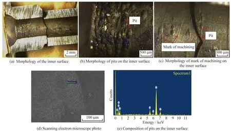
Fig.3 Fracture micrographs of the crack extending area on the inner surface of the needle valve body
The ideal structure state of the carburizing layer should be cryptocrystalline martensite and dispersed fine carbide.The carbide morphology of the carburi-zing layer plays a crucial role in the wear resistance and durability of the needle valve body.The car-bides in this paper form a network structure along the grain boundaries of the local carburizing layer.The network carbide leads to poor interfacial binding force and a cleavage effect on the matrix,which destroys the continuity of the matrix,substan-tially weakening the grain boundary strength and leading to material embrittlement[9-11].Carbide is a brittle phase:when the hard and brittle carbide in-creases and forms a network aggregation,the strength,contact fatigue strength,and wear resistance of the surface carburizing layer will decrease,and the brittleness will increase considerably,leading to stress concentration and the formation of crack sources.
The working environment of the needle valve body is mainly comprised of high-temperature fuel oil at around 200 ℃,which can produce sulfide after the decomposition of mercaptan,thioether,and disulfide in the fuel oil.Consequently,sulfides react with water and oxygen,which are combined to form polysulfide and sulfite during the diesel combustion process[12],accelerating the corrosion of the needle valve body material.The sulfide is easily invaded in the presence of a network carbide precipitation on the grain boundary.Considering the infiltration layer with the network carbide,the crack is highly likely to propagate along the grain,which is con-sistent with the conclusion of fracture surface analysis by scanning electron microscopy.
The formation of network carbide is generally due to the high carburizing carbon potential or the slow cooling rate of the sample cooled in a carburizing tank during carburizing heat treatment.This analysis revealed that the primary carburizing heat treatment failed to austenite the carburizing layer of the sample completely,resulting in the integration failure of the carbide into the austenite.Therefore,the optimal carburizing layer structure could not be obtained.Cracks were also generated on the inner surface of the carburized layer,and then the transverse crack propagation led to the fracture of the needle valve body during its working process.
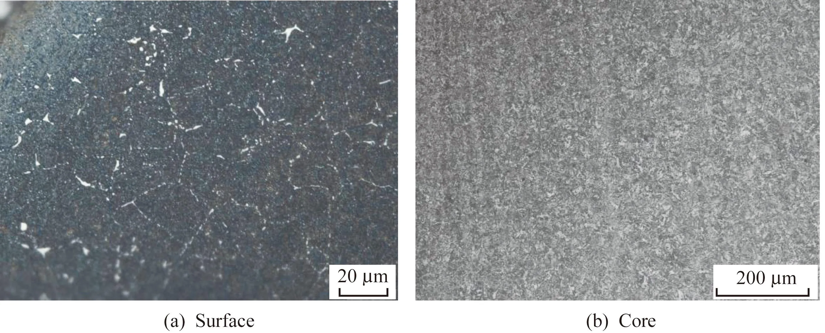
Fig.4 Microstructures of the surface and core of the needle valve body
4 Conclusions
The fracture mode of the R18CrNi8 needle valve body is a transverse fracture.The analysis results reveal that the fracture cracks originate from the inner surface of the small shoulder of the needle valve body.Cavitation damage and local machining defects observed on the inner surface and cracks initiated under the high-temperature and mechanical vibration working environment were observed due to the poor carburizing layer,thus markedly reducing the service life of the product.
This paper introduced some improvement measures according to the aforementioned failure reasons:① improve the machining quality of the needle valve body as far as possible,especially the finish-ing quality of the inner hole;② reduce the carbon potential during the carburizing process of the needle valve body to avoid the production of mesh carbide;③ prolong tempering time to reduce the influence of internal stress,resulting in a dense carburized layer structure.Cracking of the needle valve body after taking the above measures was not observed in accordance with the user feedback.
杂志排行
Baosteel Technical Research的其它文章
- Research progress on protective coatings against molten nitrate salts for thermal energy storage in concentrating solar power plants
- Effect of quenching and tempering processes on properties and microstructure ofG115 steel
- Study on gas metal arc welding of two types of TMCP steels
- Accuracy analysis of iron content of galvanized coating using an X-rayfluorescence spectrometer with an L-spectrum
- Effect of lump ore ratio on the metallurgical properties of blast furnace charge
- List of winners of excellent papers of Baosteel TechnicalResearch in 2023