A multithreaded parallel upwind sweep algorithm for the SN transport equations discretized with discontinuous finite elements
2024-01-10ZhiWeiZongMaoSongChengYingChiYuZhiMinDai
Zhi-Wei Zong · Mao-Song Cheng,2 · Ying-Chi Yu,2 · Zhi-Min Dai,2
Abstract The complex structure and strong heterogeneity of advanced nuclear reactor systems pose challenges for high-fidelity neutron-shielding calculations.Unstructured meshes exhibit strong geometric adaptability and can overcome the deficiencies of conventionally structured meshes in complex geometry modeling.A multithreaded parallel upwind sweep algorithm for SN transport was proposed to achieve a more accurate geometric description and improve the computational efficiency.The spatial variables were discretized using the standard discontinuous Galerkin finite-element method.The angular flux transmission between neighboring meshes was handled using an upwind scheme.In addition, a combination of a mesh transport sweep and angular iterations was realized using a multithreaded parallel technique.The algorithm was implemented in the 2D/3D SN transport code ThorSNIPE, and numerical evaluations were conducted using three typical benchmark problems:IAEA, Kobayashi-3i, and VENUS-3.These numerical results indicate that the multithreaded parallel upwind sweep algorithm can achieve high computational efficiency.ThorSNIPE, with a multithreaded parallel upwind sweep algorithm, has good reliability, stability, and high efficiency, making it suitable for complex shielding calculations.
Keywords Shielding calculation · Discrete ordinates method · Discontinuous Galerkin finite element method · Unstructured meshes
1 Introduction
High-fidelity neutron-shielding calculations are an essential part of advanced nuclear reactor system design.The discrete ordinate (SN) method is one of the most popular deterministic particle transport methods owing to its high angular resolution [1].Reliable modeling and simulation of SNtransport depend on two key essential conditions and fundamental components: reasonable spatial discretization schemes and mesh distributions with sufficient modeling fidelity.The two key factors interacted with and supported each other throughout the process.
Conventional Cartesian structured grids are widely used and implemented because of their regular arrangement and friendliness to finite-difference (FD) spatial discretization schemes [2–4].However, there is no general robust meshing algorithm for acquiring exact descriptions of complex structures for realistic modeling and simulations [5].Adaptive mesh refinement techniques retain the original mesh distribution features and mark cells with large errors for refinement [6].Local error estimation techniques and geometric data structures play significant roles in determining the stabilities and computational efficiencies of these systems.Unstructured grids use piecewise flat or curved surfaces to provide complicated geometries with the highest possible flexibility.With the development of the finite element method (FEM), unstructured grids have been widely applied to reactor physical analyses [7], multiphysics simulations[8], and thermal-fluid dynamics [9].Combining finite element numerical methods and the SN method with unstructured meshes has become a trend in nuclear shielding design.
Unfortunately, the first-order SN equation cannot be solved stably using the continuous FEM [10].However,while the solutions to this hyperbolic equation are smooth along the streamlines, they may be discontinuous perpendicular to the chosen direction.To obtain a robust solution,several Petrov–Galerkin (PG) approaches that update the test function as the sum of the trial functions and introduce an additional stabilization term [11–13].It was observed that the free stabilization parameter affects the convergence of the SNequation and raises uncertainty because it is usually considered as a matter of experience.Additionally, PGs cannot generally produce symmetric positive-definite coefficient matrices or inherit the best approximation property when the transport equations contain nonself-adjoint operators.
The discontinuous Galerkin finite element method(DGFEM) is a different category of stability improvement.This was pioneered by Reed and Hill for neutron transport problems in the early 1970s [14].The DGFEM connects adjacent elements through the incoming interface fluxes from the upwind (upstream) meshes and applies the usual FEM procedure to a single mesh.However, the number of unknowns in the DGFEM is much larger than that in the continuous FEMs, which demands a matrix assembly and solution method.The standard matrix assembly procedure looks for a reliable iterative solver for a banded sparse system matrix solution and must handle the storage brought on by the increased freedom [15].The matrix-free strategy stores the diagonal blocks and realizes the inversion of the transport operator by means of the matrix–vector product;however, a sum factorization technique to enable translation between vector entries and values or gradients in quadrature points is required [16].Another commonly used technique is the conventional sweeping procedure, such as FDs, in which parallelization of the sweeping procedure is implemented to reduce the computing time, which may become important in a large SN order.
In terms of parallelization, complex grid connection relationships and irregular element sweep orders pose challenges to the algorithms.In 2000, Plimpton described an asynchronous, parallel message-passing algorithm that simultaneously performs sweeps from many directions across unstructured grids [17].In 2002, Pautz used a lowcomplexity list-ordering heuristic to determine sweep ordering on a partitioned mesh [18].The essence of these two algorithms is the conversion of the abstract element sweep order into a directed acyclic graph (DAG).Since 2010, several research institutions have conducted extensive studies on high-performance architectural applications [19, 20].
A multigroup 2D SN transport code, ThorSNIPE, with unstructured meshes was developed and validated [21].This code was extended to 3D SN transport calculations and employed a multithreaded parallel upwind sweep algorithm to achieve a more accurate description and improve the reliability and efficiency of transport calculations in complex geometries.The finite element method was implemented using an open-source finite element library deal.II-9.4.0[22].The deal.II is an open-source C++ program library targeted at the computational solution of partial differential equations using adaptive finite elements and focuses on generality, dimension-independent programming, parallelism, and extensibility.It includes many state-of-the-art programming techniques for solving partial differential equations, linear algebra problems, and computer science strategies and offers users a modern interface for complex data structures and algorithms.With the assistance of this library, ThorSNIPE can be made dimension-independent,supporting different mesh sizes and types of finite elements.
The remainder of this paper is organized as follows.In Sect.2, the main theory and methodology of the ThorSNIPE code are described in detail, including the SNweak-form equation based on DGFEM theory and the multithreaded parallel upwind sweep algorithm.The numerical results are presented and discussed in Sect.3.The conclusions are summarized in Sect.4.
2 Theory and methodology
2.1 Weak form of the discrete ordinates method equations
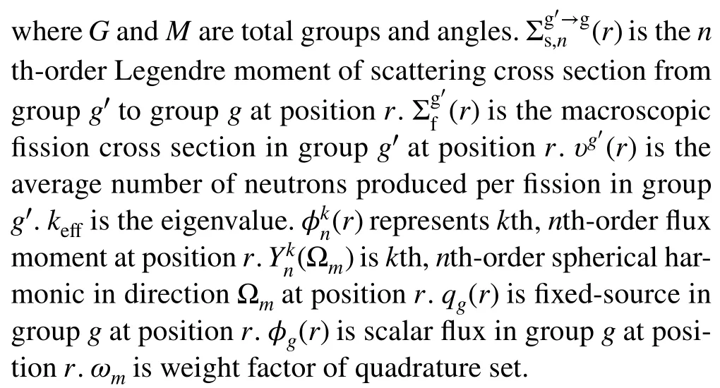
The SNform was obtained by solving the Boltzmann transport equation along discrete directions and replacing the integrals over the unit sphere with quadrature sets.The steady-state multi-group SNneutron transport equation can be written as
whereDis the domain.(r) is the angular flux in groupg, direction Ωmand positionr.is the macroscopic total cross section in groupg.(r) is a source term in groupg,direction Ωmand positionr.For fixed source problems, it can be expressed as:
and for eigenvalue problems, it can be expressed as:
Equation (1) is a linear hyperbolic equation: It is necessary to transform this “strong form” differential-integral equation into “weak form” for solving.The spatial domainDis decomposed intoKelements, which can be unstructured because the FEM is independent of the space dimension and grid choice.Consider∂Vkas the surface of thekth element andVkas the volume of thekth element, wherek=1,...,K.To obtain the weak form, Eq.(1) is multiplied by an arbitrary test functionψ∗m(r) and integrated into any elementk.Equation (1) can be rewritten in monoenergetic form as
The divergence theorem is then applied to Eq.(5),yielding:
wheren(r) is the unit normal vector to the surface of cell∂Vkat positionr.Inner products on the volume and surface of any element are introduced to express the bilinear form [23].
Substituting Eq.(7) and (8) in (6),

2.2 The discontinuous Galerkin finite element discretization scheme
The Galerkin method is theoretically based on the weighted residual method, which multiplies the original partial differential equation by a test function.Seeking a numerical approximation of the angular flux term using Lagrange polynomials of degreeP
wherebj(r) is the Lagrange shape function andφm,jis an unsolved coefficient.The matrix form is convenient for solving Eq.(10), which expressesφm,jandbj(r) in row vector notation, and Eq.(11) can be written as
In Galerkin discretization schemes, test functions share similar function space as basis functions,
Substituting Eq.(12) and (13) in (10),
The upwind scheme is the essence of the DGFEM.Notably, although the test functions on the edges are always taken from within the element, the primal functions on the edges are taken upwind with respect to the streaming direction.For outgoing edges, the primal functions are taken from within the element itself, whereas for incoming edges, the primal functions are taken from the upwind neighbor element.
2.3 Multithreaded parallel upwind sweep algorithm
2.3.1 Cell-based sweep algorithm
In the SNmethod, a transport sweep was performed for all elements along each discrete direction.The ordering in which the elements and degrees of freedom (DOF) traverse affects the speed of convergence.As mentioned in Sect.1,the DGFEM makes it possible to use a cell-based sweeping procedure in SNmethods rather than assembling a global matrix.
The element sweep order for each discrete direction in the ThorSNIPE code was developed using an upwind scheme based on the deal.II library.In our case, an array with all relevant cells is created and sorted in the upwind direction using a “dealii:: DoFRenumbering:: CompareDownstream” object in the deal.II FEM library.A straightforward 2D model with three material regions and various sweep schemes is shown in Fig.1.Cells in a conventional scheme are often categorized from edge to center to make it easier to facilitate the creation of a global matrix.The downwind system performs renumbering in the direction opposite to the discrete direction, whereas the upwind scheme manages renumbering alongside it.The definitions of “upwind” and“downwind” are determined by multiplying the unit normal vector to the cell's surface by the cosines of the corresponding discrete direction.In reality, the mesh location, discrete direction, and sweep define the order of each element.The sweep solution technique also complies with neutron transport laws.Not all pathways are mutually exclusive, and each distinct direction results in a unique order in which this solution technique can be applied.
From the perspective of solving the equations, various sweep schemes also affect the calculation of the incoming angular fluxesin Eq.(14).Primal functions obtained from neighboring elements require numerical values with a certain precision.The calculation error was gradually reduced when the transport equation was solved along the direction of particle motion using the upwind scheme.However, other schemes must process nondirectional data, adapt,and learn based on the data received.This process can be laborious and error-prone, and the accumulation of errors inevitably affects the robustness of the numerical calculation method.Thus, the entire solution procedure required more iterations.
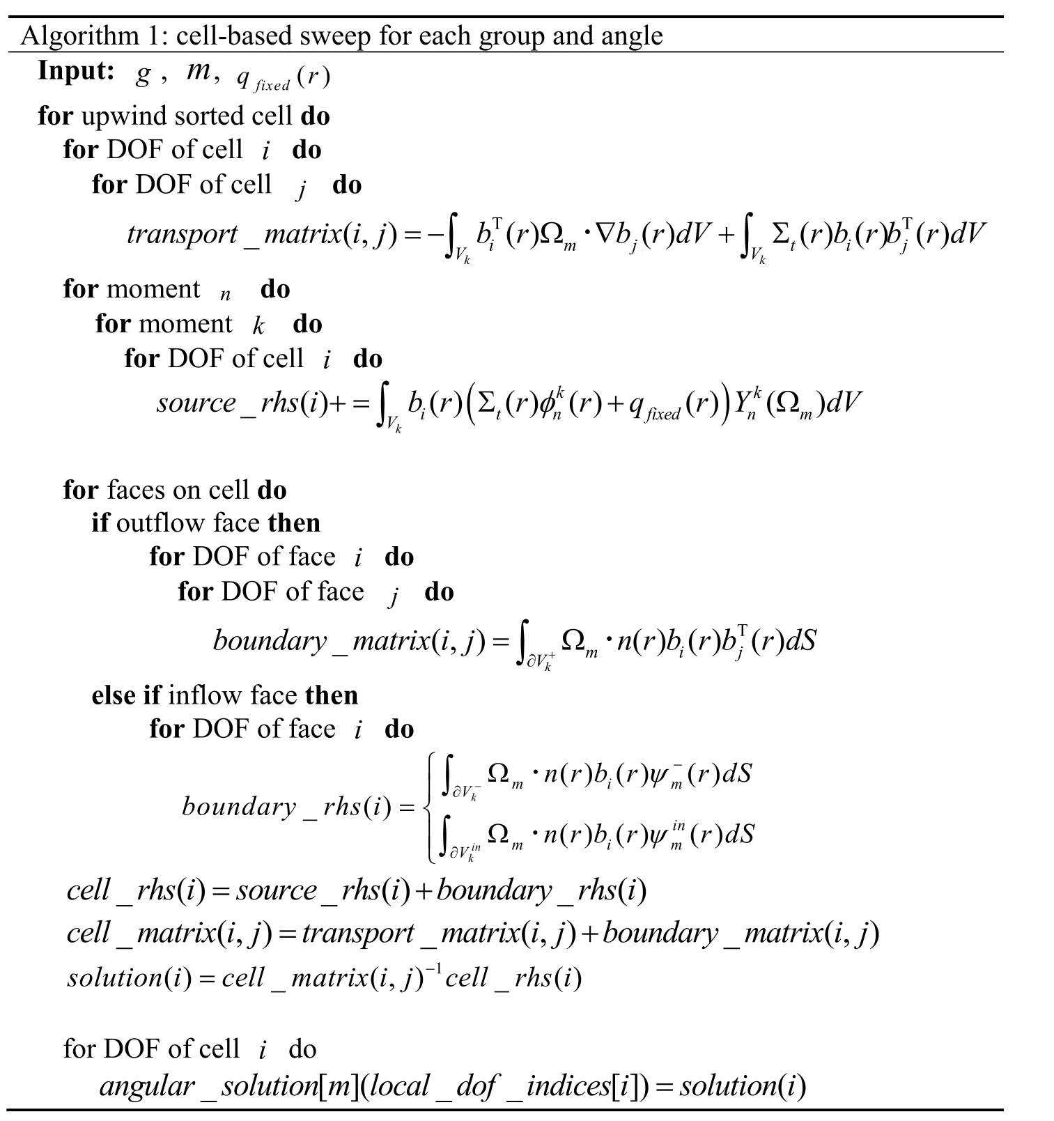
Algorithm 1 displays the cell-based sweep algorithm for each group and angle once the sweep order has been determined.The local equation can be divided into two parts as follows: The transport matrix first makes contributions from the streaming and removal operators determined by the fixed mass matrix and total cross section.Second, the right-hand side (RHS) vector includes contributions from scattering source operations and fixed source or fission source operators.The in-group and cross-group couplings comprised the contributions of the scattering sources.Lastly, a “dealii::types:: global dof index” object translates the local solution to the global angular solution.This cell-based sweep technique delivers the DGFEM solution to all cells in a single sweep order without coupling integral terms, fully utilizing the key benefits of DGFEM approaches.
The following two steps were employed to compute the local contributions of an individual cell and RHS: First, the integral is transformed from an actual cellkinto a unit/reference cell^k.For example, the streaming operator is transformed into
where the hat indicates the reference coordinates, andJ(^r) is the Jacobian of the mappingr=Fk(^r).Second, this integral is approximated using the Gauss–Legendre quadrature.This yields the formula
images/BZ_352_942_1309_988_1342.png

Fig.2 Flowchart depicting multithreaded parallel strategy
whereqis the index of the quadrature point,̂rqis the location of the reference cell, andwqis the Gaussian quadrature weight.In this study, triangular and tetrahedral grids were used for the 2D and 3D cases, respectively.
2.3.2 Multithread parallel strategy
Parallel transport computation has gained popularity in the nuclear field because of the emergence of high-performance computing clusters [24].How the processors schedule parallel jobs significantly affects the performance of code using parallel computing.The two basic techniques are spatial-domain decomposition (SDD) [25]and angular-domain decomposition (ADD) [26].SDD techniques subdivide the spatial domain into subdomains,such that the common mesh-sweep method is performed concurrently in numerous subdomains at diverse angles.However, parallelizing the SNspatial sweep is more challenging because of the upwind-downwind dependencies between the domain boundaries.
ADD techniques are frequently considered more expandable and require less memory [27].They entail a mesh sweep along a similar quadrant and are the same for all angles in the chosen quadrature [28].All operations are statically scheduled to the participating processors without negatively affecting the load balance and are ideally suited for personal computers (PCs).In shared memory machines, the traditional approach to parallelism is to break code down into threads.The deal.II leverages the threading building blocks (TBB) library [29] as basic wrappers to build an object called “tasks”.TBB offers transferable interfaces across many different platforms and abstracts the specifics of run-state signals onto individual threads.
The entire procedure for the multithreaded parallel approach in the ThorSNIPE code is shown in Fig.2.Both inner and outer iterations contain an angular loop.The number of CPU cores determines the total number of tasks in a PC system.The angular loops were divided into a specific number of subranges that were evenly distributed across the threads.A cell-based sweep sequence is used for each angular loop.A subrange is a task.The tasks are essentially independent during the iterations.They performed the calculations using the same mesh and equation structure as the respective quadrature set.However,the storage of angular fluxes is based on the local DOF indices calculated using sweep schemes.The calculation results for different subranges were collected to update the scattering source.Following the execution of the subranges, threads keep themselves busy by stealing complete portions of the subranges from other threads if they have finished their work.Thus, the code can fully exploit the system thread resource, which requires frequent interruptions by the operating system to allow other threads to execute on the available processor cores.
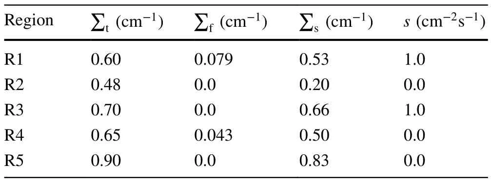
Table 1 Cross section of the IAEA 5-region fixed problem

Fig.3 (Color online) Geometry of the IAEA 5-region fixed problem

Table 2 Comparison of average flux of the IAEA benchmark
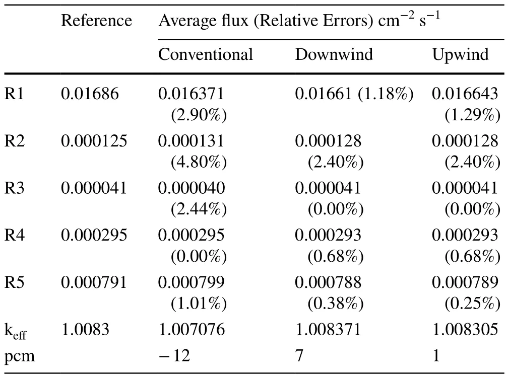
Table 3 Comparison of average flux and keff of the IAEA benchmark
3 Results and discussions
The multithreaded parallel upwind sweep algorithm is validated using three typical benchmark problems.The IAEA benchmark with five different regions was used to test the performances of the different sweep schemes.The Kobayashi-3i benchmark with cavities and bend ducts was adopted to evaluate the performance of the parallel computation for different mesh sizes and angular quadrate sets.The VENUS-3 benchmark was used to validate the algorithm’s capabilities for realistic transport calculations.In all benchmarks, convergence criteria are 10-5for the eigenvalue and 10-4for the average flux in each space interval.

Fig.4 Number of iterations with the change in the number of elements for different sweep schemes
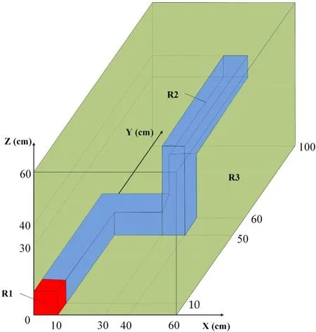
Fig.5 (Color online) Geometry of the Kobayashi-3i benchmark
3.1 IAEA benchmark
The IAEA benchmark is a 2D five-region calculation problem consisting of two large source zones and two large absorber zones surrounded by light water [30] and is designed for IAEA advanced reactor neutron transport computation.There is a strong nonuniformity in the fuel region,as shown in Fig.3.The cross sections are given in Table 1,and all boundary conditions are vacuum.

Table 4 Cross section of the Kobayashi-3i benchmark
This benchmark problem is mainly used to analyze the effect of the element sweep order on the cell-based algorithm efficiency and assert the superiority of the upwind sweep scheme.Under the PNTN-S8angular approximation,comparisons of the numerical results for the fixed source and eigenvalue cases simulated with 2338 elements are presented in Tables 2 and 3, respectively.The relative deviations in the average flux were within 2.50% in the fixed-source case and within 5.00% in the eigenvalue case.All the numerical results show excellent agreement with the references, demonstrating the accuracy and validity of the algorithm and modeling approach for such strongly heterogeneous problems.The change in the element sweep order does not make a large difference to the results.This is because the transport sweep operations were performed individually on each element, and the results were added.Because matrix addition is commutative and these operators in the equation can be described as applying a sum of matrices, the orders of various components will not impact the final result.
As shown in Fig.4, the number of iterations was compared with the change in the number of elements in the fixed-source calculation.The numerical results indicated that the upwind sweep scheme had a stable convergence speed, regardless of the number of elements.The relationship between the number of iterations and elements grows exponentially in both types of sweep schemes.The primary functions on the edges are determined based on the upwind edges with regard to the streaming direction, and transport problems involve a directional flow of information.The upwind scheme fully uses the initial boundary conditions and provides spatial flux moments for the neighboring elements.The other sweep schemes increased the number of source and power iterations required to meet the convergence criteria in the subsequent matrix calculations to compensate for the lack of constraints.In addition, no overhead cost of assembling and solving the stiffness matrix in the current framework was observed for the three sweep schemes mentioned above.Therefore, the upwind sweep algorithm can save significant computational costs with fewer iterations and is suitable for DGFEM simulations.

Fig.6 a Root-mean-square of Scalar flux L2-error versus the order of quadrature sets for the Kobayashi-3i benchmark;b speedup ratio versus the order of quadrature sets for the Kobayashi-3i benchmark

Fig.7 (Color online) Mesh distribution and scalar flux of the Kobayashi-3i benchmark

Table 5 Total flux comparison in the Kobayashi-3i benchmark
3.2 Kobayashi-3i benchmark
The Kobayashi-3i benchmark [31] is a bend duct-type problem with void regions in a highly absorbing medium, as shown in Fig.5.The cross sections used in this benchmark problem are listed in Table 4.This problem was set up to analyze the features of spatial and angular discretization and demonstrate the parallel efficiency of the multithreaded strategy.
Angular flux distribution over full domain with mesh sizes of 5 cm, 4 cm, 3 cm, 2.5 cm, and 2 cm are modeled and simulated.The quality of the quadrature sets was quantified by taking the root-mean-square (RMS) of the relative scalar flux of allNpoint detectors.

Fig.8 (Color online) Geometry of the Venus-3 benchmark

Fig.9 (Color online) Mesh distribution and fast neutron fluxes of the VENUS-3
where the reference solutionsφrefwere obtained using an analytical method [31].The RMS of the relative errors in the scalar flux using different quadrature sets versus the number of ordinates is presented in Fig.6a.It should be noted that the various approximations in the DGFEM with different mesh sizes converged at variable speeds and started to flatten as the number of ordinates increased under S20angular approximations.
The ThorSNIPE code runs on a PC with 8 cores/16 threads (one 11th Gen Intel(R) Core(TM) i7-11700F CPU running at 2.5 GHz) to demonstrate the performance and gain of the multithread technology.The speedup ratio with respect to serial mode versus the order of quadrature sets is presented in Fig.6b, where the parallel implementation efficiency exceeds 100% when the S12 angular approximations are attained, and the mesh size is less than 3 cm.The comparative results show that the proposed method can achieve a better acceleration effect as the number of meshes increases.It can also be observed that the speedup ratio increases more slowly when the S20 angular approximations are attained.In this case, each thread has over 30 parallel tasks, and memory access becomes a bottleneck in the matrix solvers for partial differential equations.The numerical results are shown in Fig.7, and the neutron fluxes at the key points are listed in Table 5.Compared with MCNP [31], the ThorSNIPE code effectively reduces angular discretization errors and fulfills the transport computational requirement to a certain degree.
3.3 VENUS-3 benchmark
The VENUS-3 benchmark was proposed to validate the capabilities of the calculation methodologies and cross-section libraries for predicting fluence rates in RPVs because it has a very clean structural geometry representing standard PWR pressure vessel conditions [32].Figure 8 illustrates the geometric configuration and material distribution of the VENUS-3 facility.The VENUS-3 model includes two types of fuel rods: the PLSA, core baffle, water reflector,barrel, Pyrex control rods, barrel, neutron pad, three types of grids, bottom support, reactor vessel, and jacket inner walls.Detailed descriptions and qualifications were obtained from the benchmark document.The benchmark arranges 386 dosimeters, with 24458Ni(n, p)58Co dosimeters, 104115In(n,n’)115mIn dosimeters, and 3827Al(n, a)24Na dosimeters placed in 268 different spatial locations.The experimental rate sets are provided as a ratio of the calculated reaction rate to the average dosimeter cross section, named the equivalent fission flux.
The numerical results shown in Fig.9 were modeled and simulated using the PNTN-S8angular discretization, 199 KASHIL-E70 neutron groups multigroup cross sections[33], and 407,819 tetrahedral elements.Figure 10 shows a C/E comparison of the equivalent fission fluxes at the three detector positions.For the115In(n, n’)115mIn dosimeters, almost all the equivalent fission flux deviations are included within ± 10%, except for a detector position (No.31 located in the core barrel with 0.7° angle) where the equivalent fission flux numerical value is affected by reflective boundary.For the27Al(n, a)24Na dosimeters, 92% of the equivalent fission flux deviations were within ± 10%, and the remaining three dosimeters overestimated the corresponding experimental values by approximately 11.9%.For the58Ni(n, p)58Co dosimeters, 95% of the equivalent fission flux deviations are limited within ± 10%, except for 11 detector positions where the equivalent fission flux numerical values overestimated the corresponding experimental values by about 10.1%–20.7%.They are concentrated at the junction of the PLSA region, outer baffle, and core barrel.The scalar flux distribution is not smooth because of the strong spatial nonuniformity of the geometry model, and higher requirements are proposed for local mesh refinement, which significantly degrades the simulated accuracy of these regions.The overall agreement between the numerical results from the ThorSNIPE code and the experimental results was very good, which shows that the ThorSNIPE code is highly reliable and stable for complex shielding calculations.

Fig.10 C/E comparison of equivalent fission fluxes at detector positions: a 58Ni(n,p)58Co from No.1 to 139; b 58Ni(n,p)58Co from No.140 to 244; c 115In(n,n’)115mIn; d 27Al(n,a)24Na
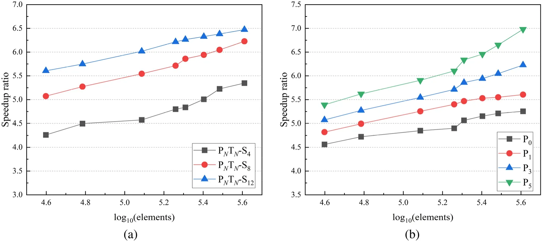
Fig.11 Speedup ratio with the change in the a order of quadrature sets; b order of Legendre expansion
The numerical results [32] from TORT-3.2 with 1,004,295 hexahedral grids and 26 BUGLE-96 neutron energy groups were selected as comparative references.For the uniformly distributed 3.3% fuel regions, TORT-3.2 with hexahedral structured meshes achieved better results.The ThorSNIPE code with tetrahedral unstructured meshes can decrease the numerical oscillation for complex regions.For the27Al(n, a)24Na dosimeters, the numerical results of ThorSNIPE tended to be lower than those of TORT-3.2 in the core barrel.This underestimation might have been caused by an error in the average dosimeter cross section.
In Fig.11, the speedup ratios of the three quadrature sets with the P3Legendre expansion order and the four Legendre expansion orders with PNTN-S8angular discretization are shown.The test conditions were consistent with TORT-3.2 code.Overall, the behavior of the proposed algorithm was similar to that of the Kobayashi-3i benchmark.For PNTN-S12, the acceleration ratio was 6.47 with 407,819 elements.Comparing the results of different expansion orders,the P5expansion order has the steepest upward trend, and the maximum speedup ratio achieved was 6.98.The numerical results indicate that the proposed algorithm achieves a favorable speedup ratio as the scale of the mesh increases,as expected.
4 Conclusion
In this study, a multithreaded parallel upwind algorithm to solve the first-order Boltzmann neutron equation is proposed and implemented in the multigroup 2D/3D SNtransport code ThorSNIPE.The cell-based upwind sweep algorithm realizes angular flux transmission between neighboring meshes and achieves a stable solution by applying DGFEM spatial discretization.The multithread parallel strategy automatically manages the angular sweep stack of each thread and improves the quality and efficiency of the ThorSNIPE code.The performance and accuracy of the proposed algorithm were tested using several typical benchmark problems.In the IAEA benchmark, the upwind sweep algorithm was proven to be the optimal method for DGFEM calculations and can save significant computational costs.The results show that the ThorSNIPE code agrees well with the reference, with a deviation of 1 pcm in eigenvalue and within 2.50% for flux distribution.In the Kobayashi-3i benchmark, the results for angular flux simulations over the full domain in different mesh sizes and quadrature set orders indicate that the multithreaded parallel algorithm has potential extensibility.In the VENUS-3 benchmark, 96% of the equivalent fission flux deviations are limited within ± 10%, except for 15 detector positions where the equivalent fission flux numerical values overestimated the corresponding experimental values by about 10.1%–20.7%.The maximum speedup ratio was 6.98 with 407,819 elements.The results of the VENUS-3 benchmark show that this robust algorithm can play a reliable role in practical engineering applications and improve computational efficiency.
In the future, angular and algebraic multigrid methods planned to solve discretized equations to overcome the reduced convergence speed of the iteration method will be investigated.Furthermore, we plan to address more complex problems to assess the accuracy and effectiveness of the proposed method and present a rigorous mathematical convergence analysis of the new scheme.
Author contributions All authors contributed to the study conception and design.Material preparation, data collection, and analysis were performed by Zhi-Wei Zong and Mao-Song Cheng.The first draft of the manuscript was written by Zhi-Wei Zong and all authors commented on previous versions of the manuscript.All authors read and approved the final manuscript.
Data availability The data that support the findings of this study are openly available in Science Data Bank at https:// doi.org/ 10.57760/ scien cedb.13607 and https:// cstr.cn/ 31253.11.scien cedb.13607.
Declarations
Conflict of interest The authors declare that they have no competing interests.
杂志排行

Nuclear Science and Techniques的其它文章
- A machine learning approach to TCAD model calibration for MOSFET
- BL02U1: the relocated macromolecular crystallography beamline at the Shanghai Synchrotron Radiation Facility
- Coin-structured tunable beam shaping assembly design for accelerator-based boron neutron capture therapy for tumors at different depths and sizes
- Simulation study of BESIII with stitched CMOS pixel detector using ACTS
- Advances in nuclear detection and readout techniques
- Enhancing betavoltaic nuclear battery performance with 3D P+PNN+multi-groove structure via carrier evolution