The biosafety level-2 macromolecular crystallography beamline(BL10U2) at the Shanghai Synchrotron Radiation Facility
2024-01-10QinXuHuaTingKongKeLiuHuanZhouKunHaoZhangWeiWeiWangMinJunLiQiangYanPanXingYaWangYuZhuWangFengYuXingYuGaoQiShengWang
Qin Xu · Hua-Ting Kong · Ke Liu · Huan Zhou · Kun-Hao Zhang · Wei-Wei Wang · Min-Jun Li ·Qiang-Yan Pan · Xing-Ya Wang · Yu-Zhu Wang · Feng Yu,2,3 · Xing-Yu Gao,2,3 · Qi-Sheng Wang,2,3
Abstract BL10U2 is an undulator-based macromolecular crystallography (MX) beamline located at the 3.5-GeV Shanghai Synchrotron Radiation Facility.BL10U2 is specifically designed for conducting routine and biosafety level-2 (BSL-2) MX experiments utilizing high-flux tunable X-rays with energies from 7 to 18 keV, providing a beam spot size of 20 µm (horizontal) × 10 µm(vertical) at the sample point.Certification by the Shanghai Pudong Municipal Health Commission confirmed the capability to perform BSL-2 MX experiments.The beamline is currently equipped with an Eiger X 16 M detector and two newly developed in-house high-precision diffractometers that can be switched to perform conventional or in situ crystal diffraction experiments.An automatic sample changer developed in-house allows fast sample exchange in less than 30 s, supporting high-throughput MX experimentation and rapid crystal screening.Data collection from both the diffractometer and detector was controlled by an in-house developed data collection software (Finback) with a user-friendly interface for convenient operation.This study presents a comprehensive overview of the facilities, experimental methods, and performance characteristics of the BL10U2 beamline.
Keywords Shanghai Synchrotron Radiation Facility · BSL-2 · MX beamline · BL10U2
1 Introduction
Resolving high-resolution three-dimensional structures of pathogens is crucial for an in-depth understanding of their mechanisms of replication, infection, and immune response,which holds great significance in the development of drugs,antibodies, and vaccines [1–3].Macromolecular crystallography (MX) is a key technique used to investigate the three-dimensional structures of pathogens with a resolution higher than 5 Å [4].Using MX to study pathogens is important not only for fundamental biological studies, but also for the urgent global demand for preventing and controlling infectious diseases.In China, the MX beamline at the Shanghai Synchrotron Radiation Facility (SSRF) is the primary site for MX research [5, 6].Internationally, several biosafety-capable MX beamlines have been established in advanced third-generation synchrotron radiation facilities to study the structure of pathogens [7–9].For instance, beamline 14-ID-B of BioCARS at the Advanced Photon Source and Beamline I03 at the Diamond Light Source were specifically designed to facilitate BSL-2/3 operations [10, 11].In China, SSRF is the only third-generation advanced synchrotron light source currently in operation [12, 13].Given the lack of an MX beamline with biosafety in China using which researchers can to study the three-dimensional structure of pathogens, the expert user community proposed constructing an MX beamline with BSL-2 at the SSRF.
As part of the SSRF Phase-II project launched in December 2016, the BL10U2 was established as China's first MX beamline with a biosafety protection function, facilitating the acquisition of structural data on pathogens by structural biologists [14].BL10U2 was specifically designed for crystallographic analysis of macromolecular and small-molecule crystals with various sizes and unit cells, facilitated by the high flux (2 × 10¹²photons/s @12.7 keV, 300 mA), small beam divergence (1.5 mrad × 0.2 mrad), and reasonably small beam size (20.0 µm × 10.0 µm) [15, 16].The monochromator in the BL10U2 was designed to deliver X-rays in the energy range of 7–18 keV, enabling multiple/singlewavelength anomalous dispersion (MAD/SAD) experiments.The performance of the BL10U2 was reviewed and verified by international review committees.The pilot run of BL10U2 commenced in June 2021 and was officially opened to the first users in January 2022.The end station is currently equipped with a large active area detector (Eiger X 16 M)[17] along with two high-precision diffractometers developed in-house, which can be switched to perform conventional cryo-crystal diffraction experiments or in situ crystal diffraction experiments.Additionally, an in-house-developed sample mounting robot enables fully automated rapid sample exchange in less than 30 s.Data collection from the diffractometer and detector is controlled by an in-house-developed data collection software (Finback) with a user-friendly interface and convenient operation.This beamline has been certified by the Shanghai Pudong Municipal Health Commission to perform routine and BSL-2 MX experiments (Table 1).This paper presents a comprehensive review of the BL10U2 beamline, including its facilities, experimental methods, and performance.
2 Beamline
The beamline was specifically designed as a BSL-2 biosafety laboratory equipped with radiation-shielding capabilities to facilitate MX studies on the structure and function of pathogens.To achieve the design objectives, three main aspects must be addressed as follows.1) Development, installation,collimation, and adjustment of the beamline components.The performance parameters of the components must be accurately designed and tested during installation.2)Installation of the experimental hutches.The experimental hutch should satisfy both radiation protection and BSL-2 biosafety standards, allowing personnel access and instrument installation.A biosafety management system should be established to meet the standards specified by regulatory agencies, and 3) construction and commissioning of the experimental station.It should enable various experiments,including traditional cryo-crystallography, in situ crystallography, automated sample mounting, and data analysis.Additionally, a series of experimental methods, such as MX studies under BSL-2 conditions, small-crystal MX studies,serial crystallography methods, anomalous diffraction methods (MAD/SAD), isomorphous replacement, and molecular replacement, should be provided.
To fulfill the requirements of virus particle crystal diffraction experiments and general small-crystal diffraction experiments in terms of energy range, energy resolution,beam size, divergence angle, and photon flux, an in-vacuumundulator (IVU22) was selected as the light source and housed in a vacuum chamber.The optical design of the beamline incorporated a two-stage horizontal focusing system and a single-stage vertical focusing system.Following the grazing of the sawtooth walls, the beam was deflected outward using a planar mirror, creating an additional transverse space between the two canted beamlines (USAXS beamline BL10U1 and P2 beamline BL10U2).White beam slits limit the beam and a double-crystal monochromator(DCM) performs energy selection.An ellipsoidal cylinder mirror pre-focuses the beam horizontally at 26.5 m, creating a secondary horizontal source point of approximately 118 μm at 33.85 m.High-precision slits are utilized to limit and adjust the beam at the secondary source point, followed by vertical focusing of the source point using an ellipsoidal cylinder mirror at 39.6 m and horizontal re-focusing using another ellipsoidal cylinder mirror at 43.1 m.These optical configurations enable the formation of a focused beam with dimensions of approximately 20 μm × 10 μm at the sample point, located at 44.8 m.The vertical focusing mirror has a surface shape error requirement of higher than 0.3 μrad to achieve single-stage focusing with a long working distance.Different beam sizes were obtained at the sample point for various experimental samples by adjusting the aperture of the secondary source slit.The use of single-stage vertical focusing allows sufficient working distance to establish BSL-2 protection within radiation-shielding huts.

Table 1 Specifications of the BL10U2 beamline
To meet the requirements of the MX experiments conducted under the BSL-2 protective conditions, the experimental station was designed and constructed in accordance with the relevant national standards.In addition to the conventional experimental setup, supplementary protective facilities and negative pressure conditions were implemented, accompanied by clearly defined sample disposal procedures.Within the experimental station, a combination of traditional cryo-crystallography and in situ crystallography experiments were conducted using two diffraction instruments that could be switched between the two modes.Diffraction data were collected using large-area,high-speed, two-dimensional detectors (Eiger X 16 M).Sample mounting was performed using an automated sample changer developed in-house to enhance experimental efficiency and environmental stability.Data acquisition was managed using our independently developed Finback user interface.A dual-function diffractometer was developed to accommodate both conventional cryo-crystallography and in situ crystallography experiments employing crystallization plates.
2.1 Light source
BL10U2 comprises four major components: light source,front end, optical hutch, and end station.The light source utilized in BL10U2 is an in-house developed small-gap IVU22 with 80 periods and a period length of 2.5 cm,which shares one straight section with the USAXS beamline BL10U1 by canting the undulators with a horizontal angle of 6 mrad.The in-vacuum undulator was constructed in-house by SSRF with a gap range of 6–12 mm in operation, covering a high-brilliant source in 7–18 keV.With a total power of 2.6 kW, the light source emitted approximately 4.85 × 10¹⁴photons/s at 12.7 keV.The dimensions of the source size are 386 µm × 26 µm (FWHM,H×V), and the flux in the central cone (81 µrad × 22 µrad@12.7 keV) amounts to 1.54 × 10¹⁴photons/s (0.1% BW).
2.2 Beamline optics
The beamline exhibits an optimal optical setup to accommodate the finely collimated undulator beam, as shown in Fig.1.The beam generated by the undulator is defined through a beam-limiting aperture located in the front-end area, resulting in an outgoing beam with a divergence angle of 0.3 mrad × 0.15 mrad (H×V).The beam is then confined by water-cooled slits (Slit 1, 19.62 m from the source point) to generate a beam with a divergence angle of 0.10 mrad × 0.05 mrad (H×V).The first horizontally deflecting mirror (M1, InSync, 21.42-m from the source point) is set to deflect the beam by 7 mrad (with an incidence angle of 3.5 mrad) toward the outside of the ring, therebyincreasing the distance between the two downstream beam lines to facilitate equipment installation.Constructed from silicon and coated with rhodium (Rh), M1 has an optically active surface measuring 700 mm (length) × 20 mm (width).The mirror surface was polished to maintain a root-meansquare (RMS) roughness of < 3° with a sagittal slope error of < 0.7 µrad.The polychromatic beam delivered from M1 was monochromatized using the DCM.
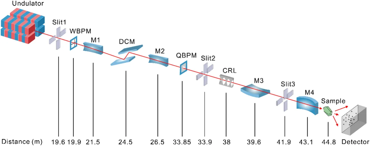
Fig.1 (Color online) Schematic layout of the BL10U2 beamline
A DCM (co-developed with the Changchun Institute of Optics, Fine Mechanics and Physics, Chinese Academy of Sciences) with two Si111 crystals was positioned 24.5-m from the source point.The DCM was cooled using liquid nitrogen to satisfy the energy coverage, energy resolution,and thermal load requirements.The vertical deflection mode was selected for the fixed-exit geometry of the DCM.Operating within a working energy range of 7–18 keV and achieving an energy resolution of ΔE/E(@12.7 keV) < 2 × 10⁻⁴,the DCM satisfactorily meets the demands for fluorescence scanning in MAD experiments, while maintaining the position and direction of the outgoing beam during energy scanning.
A fixed oval cylindrical horizontal pre-focusing mirror(M2, WinlightX) was employed to focus the beam horizontally, resulting a secondary light source point with a horizontal size of approximately 118 µm at 33.85-m from the source point.The M2 surface was coated with Rh and had an incident angle of 3.5 mrad.The radial surface shape error of M2 remains lower than 0.5 mrad to ensure the desired size of the horizontal focus spot.
High-precision secondary light source slits (Slit 2),33.85-m from the source point, defined the size of the secondary light source in the horizontal direction.The opening of the secondary light source slits can be adjusted to obtain the desired beam spot at the sample point for different experimental samples.
The secondary light source slits are followed by a horizontally deflecting Kirkpatrick–Baez (KB) mirror at 43.1 m and a vertically deflecting KB mirror at 39.6 m.Slits 3 and 4 were utilized to limit the irradiation range of light beam on the surfaces of KB mirrors.The KB mirrors were manufactured using silicon and coated with Ru, enabling X-ray energies of up to 18 keV.Both the vertical and horizontal focusing mirrors maintained a swept incidence angle of 3.5 mrad.The vertical focusing mirror (M3, JTEC) has a length of 0.43 m to accommodate the vertical incident X-ray divergence angle of 50 μrad when the entire beam is captured.The horizontal focusing mirror (M4, WinlightX) was 800 mm long, and the secondary light point was received at an angle of 0.29 mrad.After the KB mirror, a focused spot of 20 μm × 10 μm can be achieved at the sample point with a divergence angle of approximately 1.5 mrad × 0.15 mrad.
The beam position monitoring system for monitoring and diagnosing the beam included a white beam fluorescent screen, three monochromatic beam fluorescent screens, a Wirescan beam probe monitor (WBPM), and a quadrant beam position monitor (QBPM, FMB Oxford).A fluorescence screen can be inserted into the beam to observe white and monochromatic beams.An image on the fluorescent screen was recorded using an external video camera and displayed online.The WBPM developed in-house was used to scan and analyze the beam profile [18], whereas the QBPM monitors the stability of the beam at the secondary light source point.The beam spatial stability in 3000 s was investigated using QBPM between M2 and M3, with a theoretical calculation value of (846,H, FHWM) μm × (120,V, FHWM) μm for the beam spot size at that location.The results demonstrated the long-term stability of the beam,both horizontally and vertically.The standard deviation of the beam's horizontal fluctuations was 2.9 μm, whereas the vertical fluctuations had a standard deviation of 6.8 μm.The vertical direction exhibited more pronounced fluctuations than that in the horizontal direction, which were attributed to the fluctuations caused by the DCM (Fig.2).There are two beryllium (Be) windows located after the DCM and a vertically deflecting KB mirror to separate and protect the components in an ultra-high vacuum environment.The beamline is tunable within the range of 0.82–2.48 Å, although it typically operates in the 0.82–1.8 Å range.The flux of the focused beam at 1 Å is approximately 2 × 10¹²photons/s.
3 Experimental station

Fig.2 (Color online) Time-domain analysis of beam position on QBPM
The experimental station was located at the terminus of the BSL-2 macromolecular crystallography beamline, with a temperature stability of 25 ± 1 °C and low relative humidity of less than 30% [19].After passing through a vertical focusing mirror, the monochromatic beam traverses a Be window and attenuator comprising aluminum foils of varying thicknesses.This configuration enables the production of an attenuated X-ray beams according to user specifications.To optimize the beam intensity and position during the motor scans, an ionization chamber (Tianjin Jingshenfang Technology Co., Ltd.) was utilized.The environment around the sample included a goniometer, on-axis camera, cryocooler,beamstop, fluorescence detector, and horizontal diffractometer.An overview of the end station, environment around the sample, and one tab of the graphical user interface is shown in Fig.3.
The experimental station incorporated a combination of conventional low-temperature cryo-crystallography and in situ crystallography experiments, facilitated by a seamless transition between two sets of diffractometers.Two new high-precision diffractometers developed in-house (horizontal for conventional cryo-crystal diffraction experiments and vertical for in situ crystal diffraction experiments) were installed on a stand separate from the detector support table to ensure minimal disruption of the sample-beam alignment when moving the detector.The diffractometer comprises mainly an air-bearing goniometer with a sphere of confusion(SOC) < 1 µm, high-precision sample centering system, onaxis microscope, backlight, ultrafast shutter, movable beamstop, and changeable collimators.Additionally, an active beamstop was positioned after the sample blocked the beam.A compound refractive lens (CRL) located after Slit 2 can be inserted to defocus the beam, allowing adaptation to crystals of varying sizes.The maximum defocused beam size was approximately 70 µm × 40 µm (FWHM) at 12.7 keV.The beam size depended on the X-ray energy when the CRL was inserted.Therefore, beam-shaping apertures of varying sizes (20 µm, 50 µm, 100 µm, 200 µm, or 300 µm) can be selected to define the irradiation area, accommodating crystals of different sizes.The sample was visually centered using an on-axis camera at four fixed magnifications.The captured digital image was displayed in a browser window and integrated into the Finback control software.
The sample environment temperature was controlled using an Oxford Cryostream800, and a temperature of 100 K was typically used for the MX experiments.However, thetemperature of the sample environment was adjustable within the range of 80–350 K, enabling MX experiments under variable temperature conditions.

Fig.3 (Color online) The BL10U2 end station and the Finback GUI.a The BL10U2 end station.b The environment around the sample.c The Finback GUI
The diffraction data were collected using an EIGER X 16 M detector, providing flexibility in sample-to-detector distances ranging from 115 to 900 mm (resolution 0.95–4.1 Å at 12.662 keV).The detector allows for fast and shutterless operation with frame rates of up to 133 Hz, enabling the collection of a complete set of oscillation data in less than 9 s.Automatic changes in the detector position were implemented when different resolutions were selected.
Advancements in fast X-ray detectors and beamline automation have highlighted the importance of efficient sample handling in MX experiments.To address this, there is a need for an automated sample changer that offers key features,such as high speed, ample storage capacity, reliability, and user-friendly operation.However, before the establishment of BL10U2, commercially available ACTOR sample changers used at the MX beamlines in SSRF faced limitations in terms of functionality, performance, and maintenance,significantly impeding the efficiency of crystal diffraction data collection.Therefore, we developed an independent automated sample changer specifically designed for MX experiments to overcome these challenges.Samples can be mounted either manually or using an in-house-developed sample changer called swordfish, which requires approximately 20 s to remove a crystal sample from the goniometer and replace it with a new one in the storage Dewar capable of storing 320 samples (20 pucks) at a time.A barcode reader was used to scan the crystal information, which was useful for recording information during high-throughput crystal screening.A standard pin with a length of 18 mm is recommended.Routine calibration and maintenance ensure reliability, and an increasing number of crystals have been easily screened since the installation of swordfish.
4 Experiments methods
A variety of experimental methods can be utilized to investigate the structure of biological macromolecules, including multiple- and single-wavelength anomalous diffraction(MAD/SAD), molecular replacement, shutterless data collection, in situ diffraction, and crystal diffraction experiments involving infectious pathogens (BSL-2 level) [20–23].Notably, two operating modes are offered in this beamline:normal mode and BSL-2 mode.In the normal mode, the sample is held in a loop and cryoprotected.In contrast,in situ data collection is compulsory in the BSL-2 mode,which captures diffraction patterns directly from crystals securely sealed within their crystallization plates at room temperature to minimize biohazard risks.
5 BSL-2 Operation
5.1 Architecture design
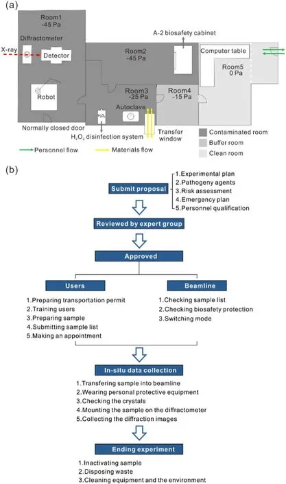
Fig.4 (Color online) Upper: Layout of the end station of BL10U2.Lower: Experimental flowchart procedures of proposal submission,review, experimental preparation, in situ data collection and experiment ending performed in BL10U2
The experimental station comprised distinct areas: experimental room (Room 1), preparation room (Room 2), buffer room (Rooms 3 and 4), and control room (Room 5), each maintaining a specific pressure differential.Through a thoughtful layout design and implementation of safety measures, the experimental station simultaneously met both the BSL-2 biosafety requirements and radiation protection standards (Fig.4a).Room 1 served as the experimental space in the experimental station, enabling users to follow the designated procedures for radiation experiments.Users search for the hutch and close the endstation door before opening the photon shutter to allow X-rays to irradiate the sample.Notably, manual handling of mounted samples is unnecessary, as all equipment can be controlled using dedicated software.In Room 2, the users had access to a Class II Type A2 biological safety cabinet, which provided a secure environment for examining the crystallization plate.Room 3 primarily served as the area for sample transfer.Room 4 was designed to wear personal protective equipment (PPE), including laboratory gowns, N95 respirators, headcaps, gloves, protective eyewear, and shoe covers, before entering rooms 1, 2, and 3 during the BSL-2 mode.It is worth noting that PPE is not required in the normal mode.Room 5 was dedicated to data collection activities and utilized specialized software(Fig.4a).A negative pressure gradient was set from room five to one, depending on the functionality of each room.For instance, Room 5 maintains a constant pressure, as it is necessary for control operations conducted by researchers over an extended period.Room 5 was designated as a clean environment.The pressures in Rooms 3 and 4 were set at - 25 Pa and - 15 Pa, respectively, to facilitate sample transfer and post-experiment disinfection in Room 3,as well as the wearing of PPE in Room 4.Rooms 1 and 2 maintained the lowest pressure at - 45 Pa, enabling researchers to perform operations such as sample opening, movement, mounting, irradiation, and dismounting.
The experimental station was equipped with two entrances and exit doors.One of the entrances was exclusively designated for equipment transfer and remained closed throughout the experiment.The other entrance implements access control measures to regulate operator entry.A transfer window was used to introduce the sample into the laboratory, as indicated by the yellow section in Fig.4a.Currently, biohazardous samples are disinfected and disposed after data collection and transported through a transfer window (Fig.4a).
5.2 Sample list
In compliance with the "List of Human Pathogenic Microorganisms" issued by the Ministry of Health of China [24],and based on a questionnaire survey conducted among relevant research groups in China, it has been established that 39 specific virus species are approved for experimental activities involving inactivated materials at this beamline.Consequently, all operations performed at this beamline exclusively involved inactivated viral crystals.To facilitate structure determination, it is imperative to prepare the virus samples in crystal form, which requires their preparation in a qualified wet lab on the users' side.
5.3 Proposal management
The submission of user proposals must be completed online and undergo thorough evaluation by an external expert committee comprising members from different research disciplines.These proposals should provide comprehensive information regarding the experimental plan, pathogenic agents utilized, associated risks, emergency procedures, and qualifications of the personnel involved.Committee experts have scientific expertise in structural biology, crystallography, virology, and biosafety.The evaluation process considered the overall research risk assessment and examination on a case-by-case basis.In exceptional cases involving novel pathogenic agents, the final decision rests with the biosafety committee, considering the relevant regulations and circumstances.Upon approval of the proposals, users were required to obtain transportation permission from the appropriate authority.All individuals engaged in the experiment undergo comprehensive online and on-site training and receive certification from the beamline staff.Users are responsible for scheduling their experiments in advance, allowing enough time for the beamline staffto ensure the implementation of the biosafety measures and protocols.If users opt to use the BSL-2 mode, they must comply with relevant laws and regulations and complete experimental preparations, in situ data collection, and experiment termination under the guidance of the SSRF biosafety management system documents(Fig.4b).
5.4 Data collection in BSL-2 mode
In the BSL-2 mode, virus crystals are enclosed within minute cells of a crystallization plate, and X-rays are used to irradiate the samples, generating a diffraction pattern on the detector.Currently, several commercially available 96-well crystallization plates can be used for in situ experiments on this beamline, such as the In Situ-1 Crystallization Plate(MiTeGen), CrystalQuick X plate (Greiner Bio-One), and CrystalDirect plate (MiTeGen).A recently developed microplate by our group is another option [25].For the in situ diffraction data collection with 96-well crystallization plates,the effective oscillation range will be - 5° to 5°.For the microplates, the range was approximately 300°.The complete dataset was obtained using the BLEND program in the CCP4 suite of programs [26, 27].The samples were visually examined using an on-axis microscope.However, achieving precise crystal alignment is challenging due to the presence of the surrounding liquid and sealing membrane.To overcome the limitations associated with optical observations,the grid scan technique can be employed as an alternative approach that utilizes low-dose X-ray radiation.This method allows scanning across multiple regions of the sample to improve data quality.After completion of the experiment,the samples and associated materials were sterilized via high-pressure autoclaving.Subsequently, proper disposal should be conducted by authorized agencies.Additionally,the equipment and experimental areas were sterilized by exposure to ultraviolet lamps for one hour and hydrogen peroxide vapor room decontamination with a total cycle time of 4–5 h, as required to ensure thorough decontamination.
6 Control and data acquisition system
In BL10U2, control and data acquisition were performed by the Experimental Physics and Industrial Control System(EPICS) [28, 29] and Finback software, an in-house developed integrated control and data acquisition system with an intuitive graphical user interface (GUI) accessible through a web browser.
EPICS input–output controllers (IOCs) manage the motor control and signal readout in the VME crates.Linux-based IOCs are also employed for other module devices such as the Galil motor controller and axis network devices.The beamline components controlled by EPICS were implemented by the control group of the phase-II beamlines.
In modern MX experiments, user-friendly software and interfaces play a crucial role in improving experimental efficiency.The client GUI of Finback, which leverages cutting-edge web technologies such as WebSocket, WebGL,WebWorker, and WebAssembly, is compatible with modern browsers.Finback supports multiple concurrent sessions and enables both on-site and remote access.It integrates control over the essential equipment, including the goniometer, beam aperture, shutter, detector, camera, and sample changer.Additionally, the Finback software facilitates automated sample loading through robotic arm control, reducing the researcher’s workload.This simplifies the workflow by enabling crystal autocentering using coaxial cameras.By leveraging Finback, a wide range of techniques commonly used in MX experiments have become accessible, such as single-shot, multi-shot, and full dataset collection, X-ray grid scanning, helical data collection, anomalous scattering scans, and inverted data collection methods utilized in anomalous scattering signal crystallography.
An automated data processing pipeline integrating the commonly used protein crystallographic software,Aquarium, was developed for online cell refinement and data reduction [30].Dataset collection triggers automated indexing, full integration, and scaling within pipelines.The data processing module Porpoise integrates the CCP4[31], XDS [32], DIALS [33], and SHELX packages [34],which are designed to automatically process datasets from data reduction to model building when the protein sequence is provided (or to the main-chain building, if the protein sequence information is not available).The pipeline operates on servers located at the Big Data Science Center (BDSC) of the SSRF.The BDSC is a part of the SSRF Phase-II project and offers storage and computer resources for all beamlines[35].All data generated during the experiment, including diffraction images, sample information, and reduction results, were stored in the BDSC for long-term archival.The current policy is that the experimental data can be stored for three years on a hard disk.As the volume of data increases,old data are transferred to tape drives.
7 First commissioning results
Excellent results were obtained during the commissioning of BL10U2.We present the first commissioning results of this beamline, including the energy range, energy resolution,photon flux, beam size, beam divergence at the sample point,BSL-2 biosafety protection, sample screening speed, and highest diffraction resolution.
7.1 Energy range
The energy range of the beamline was determined by measuring the K absorption edges of Mn and Zr.The measurements were performed under specific test conditions: a beam current of 200 mA, an acquisition step of 1 eV, and an acquisition time of 1 s per point.Observations of the Mn absorption edge (6.55 keV and Zr absorption edge (18.00 keV demonstrated that the photon energy of BL10U2 can be adjusted within the range of 6.5–18.05 keV (Fig.5).
7.2 Energy resolution
To assess the energy resolution, the width of the rocking curve of the second crystal, Si111, of the DCM was utilized.The measurements were performed under specific test conditions: a beam current of 200 mA, an energy of 12.7 keV, room temperature, an acquisition step of 0.0002°,and an acquisition time of 1 s per point.The photon flux was recorded using an ionization chamber placed behind the exit Be window during the scanning of the pitch of the second crystal, Si111, of the DCM.The FWHM value was obtained and averaged to be 0.001604°.The energy resolution of BL10U2 is obtained as (1.78 ± 0.02) × 10–4, calculating by the energy resolution formula ΔE/E= Δθ× cotθ(Fig.6).
7.3 Photon flux at the sample point
The photon flux at the sample point was measured using an ionization chamber placed behind the Be window exit.The test conditions included a beam current of 200 mA, an energy of 12.7 keV, room temperature, and an ionization chamber length of 10 mm.The obtained photon flux at thesample point was (2.52 ± 0.01) × 1012photons/s for a beam current of 300 mA.To monitor the stability of the photon flux, its variation was recorded for one minute (a typical time for collecting a set of data), and the results indicated that the photon flux fluctuated by approximately 1% (Fig.7).A fast Fourier transform (FFT) analysis of the time-dependent curve of the ionization current was performed to analyze the causes of the fluctuations.As shown in Fig.8, the fluctuations with low-frequency vibrations originate from the surrounding environment, which is the major source of slow fluctuations.Power and mechanical vibrations contribute to these fast fluctuations.This suggests that more effort should be made to reduce fast fluctuations in future.
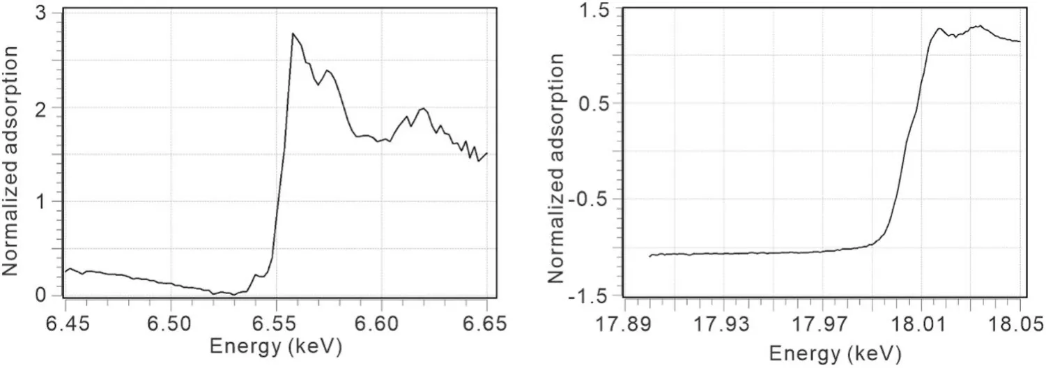
Fig.5 Mn and Zr X-ray absorption edges
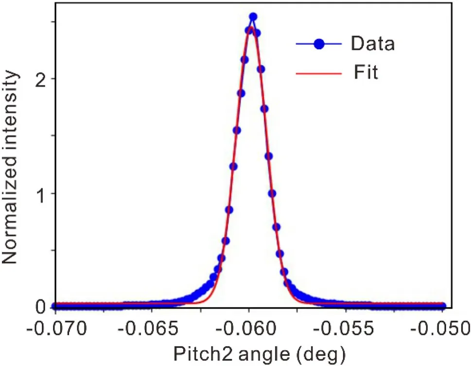
Fig.6 Rocking curve widths at 12.7 keV

Fig.7 Time chart of the measured ionization current variation over 40 s
7.4 Beam size at the sample point
A metal wire was positioned at the sample point, and an ionization chamber was used to record the beam intensity.The beam size was obtained by recording the beam intensity while scanning a metal wire in the vertical and horizontal directions.The measurements were performed under test conditions of a beam current of 200 mA and an energy of 12.7 keV.The calculated beam size (FWHM)closely matches the target design value, yielding (16.8 ± 0.1,H) µm × (9.4 ± 0.6,V) µm (Fig.9).
7.5 Beam divergence at the sample point
To obtain the horizontal and vertical beam divergence at the sample point, fitting was performed using the beam size at the sample point (H0,V0) and the beam size at 0.51 m (L)downstream of the sample point along the optical path (H1,V1).The test conditions for this analysis included a beam current of 200 mA and energy of 12.7 keV.The following equation was used for data fitting:
By deconvolution, the beam divergence at the sample point was calculated as (0.187 ± 0.006) mrad × (0.411 ± 0.003) mrad.
7.6 Sample screening speed
For sample screening, a puck containing 16 lysozyme crystals was placed in the Dewar sample.An in-house-developedsample changer (Swordfish) was used for sample screening.Finback software was used to control the sample loading,sample alignment, and sample diffraction data acquisition at one angle to test the number of screening samples that could be completed in one hour.The test conditions included a sample changer, diffractometer, Eiger X 16 M detector, and Finback software.According to the expert's on-site actual test, BL10U2 can screen 33.76 samples in one hour, based on the experimental procedure of sample change, sample alignment, and diffraction image acquisition.

Fig.8 FFT analysis of the ionization current
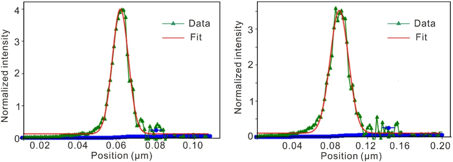
Fig.9 Focused beam profiles at sample point in horizontal and vertical directions
7.7 Highest diffraction resolution
The crystal plane diffraction of the LaB6specimen (511)was measured at an energy of 18 keV and a detector-sample distance of 130 mm using Finback and Albula software.The experts’ on-site measurements confirmed the clear visibility of the 24th diffraction ring in the LaB6 diffraction pattern.The highest resolution achieved was 0.673 Å, surpassing the target of 0.800 Å (Fig.10).
7.8 Commissioning summary
Following a discussion and review of the commissioning outline of BL10U2, the expert group concluded that the test content was comprehensive, the applied methods were accurate, and the test equipment was reliable.The results of the on-site test demonstrated that the measured values for all specifications of the BL10U2 met or exceeded the design specifications.An expert group collected the crystal diffraction data of lysozyme at BL10U2 and performed data processing, subsequent structure analysis,and model correction.The quality of the diffraction data and model met international standards, indicating that BL10U2 fulfilled the necessary conditions for user access(Table 2).
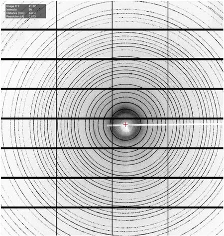
Fig.10 X-ray diffraction image of LaB6 taken on the diffractometer
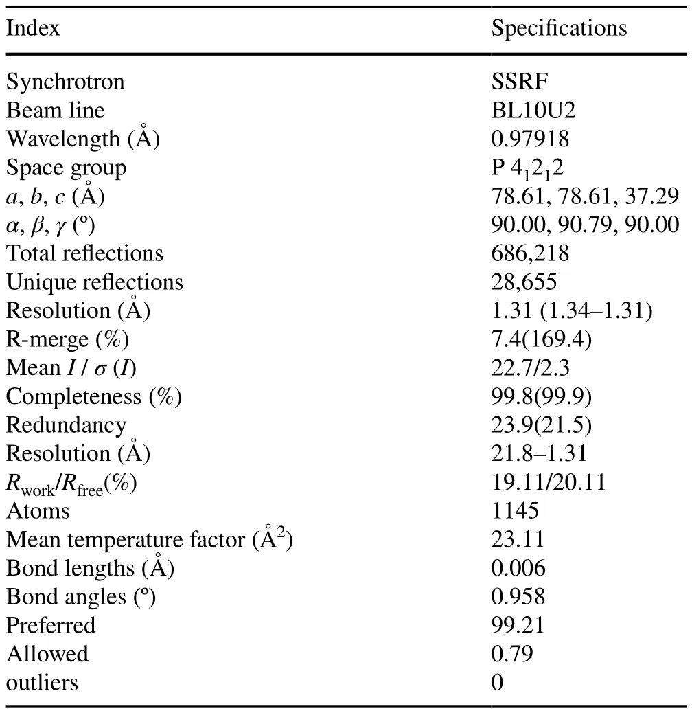
Table 2 Statistics for data processing and model refinement of lysozyme
8 Operation status and user achievements
The beamline commenced trial operation in June 2021,accumulating 6986 operating hours, including user-supplied time accounting for 3830 h (including both trial and regular operations).By June 2023, 131 experimental projects from 218 research groups were completed.
Since its trial operation, the beamline has enabled the publication of 50 research papers by users, including two in Cell, seven in sub-journals of Nature, Science, and Cell,and 23 in Q1 journals.A notable publication appeared in Cell on January 5, 2022, titled "Receptor binding and complex structures of human ACE2 to spike receptor-binding domain (RBD) from Omicron and Delta SARS-CoV-2".This study elucidated the structure of the complex formed by the receptor-binding domains (RBDs) of the Omicron and Delta variants of SARS-CoV-2 and human ACE2,shedding light on their molecular interaction mechanisms.These findings provide critical molecular insights into Omicron and Delta variants and serve as a fundamental basis for vaccine development and drug screening [36].Furthermore, a research paper titled "Structural basis of human ACE2 higher binding affinity to currently circulating Omicron SARS-CoV-2 subvariants BA.2 and BA.1.1"was published in Cell on June 15, 2022.This study identified the binding affinity sequence between human angiotensin-converting enzyme 2 (hACE2) and four early omicron subvariants (BA.1, BA.1.1, BA.2, and BA.3) in the RBD and revealed the structural basis underlying their distinct hACE2 binding modes [37].Most recently, on September 11, 2023, a research paper entitled "Molecular mechanisms of SARS-CoV-2 resistance to nirmatrelvir"was published in Nature (Accelerated Article Preview).This study sheds light on the mechanisms by which SARSCoV-2 evolves resistance to current protease inhibitors and lays the foundation for designing next-generation Mpro inhibitors [38].These studies significantly contributed to the development of broad-spectrum therapeutic antibodies and vaccines against COVID-19 based on experiments conducted at BL10U2.In addition, the beamline supports 11 industrial users and provides 353 h of user-supplied time, thereby offering advanced research techniques for relevant industries.
9 Summary and conclusion
The BL10U2 beamline was designed specifically for conventional and BSL-2 MX studies.In this study, a technical description of the main components is provided, and the first commissioning results are presented.The pilot run of BL10U2 commenced in June 2021 and was officially opened to the first users in January 2022.The BL10U2 operates in two modes: normal (without biosafety protection) and biosafety.Conventional MX experiments can be conducted in the normal mode, whereas the biosafety protection mode enables BSL-2 pathogen crystallography experiments.A beam with a small size and high brightness, as well as an in-house-developed robotic sample changer, high-precision diffractometers, data acquisition software, and an automated data processing pipeline running with high reliability, effectively reduces the cost of macromolecular structure analysis and increases the efficiency of research.A diverse range of scientific investigations has been carried out at BL10U2,including conventional macromolecular crystallography,MAD/SAD macromolecular crystallography, and small molecular crystallography.Recent scientific findings have also been reported in the literature.The BL10U2 beamline will enable Chinese researchers to study the structure of living viruses and contribute to the prevention and control of infectious diseases.
Acknowledgements We thank the staffof Department of Beam Engineering Technology in SSRF for engineering design and installation and the financial supporting of SSRF Phase-II project.
Author contributions All authors contributed to the study conception and design.Material preparation, data collection, and analysis were performed by Qin Xu, Hua-Ting Kong, Ke Liu, Huan Zhou, Kun-Hao Zhang, Wei-Wei Wang, Min-Jun Li, and Qiang-Yan Pan.The first draft of the manuscript was written by Hua-Ting Kong, and all authors commented on previous versions of the manuscript.All authors read and approved the final manuscript.
Data availability The data that support the findings of this study are openly available in Science Data Bank at https:// www.doi.org/ 10.57760/ scien cedb.13554 and https:// cstr.cn/ 31253.11.scien cedb.13554.
杂志排行

Nuclear Science and Techniques的其它文章
- A machine learning approach to TCAD model calibration for MOSFET
- BL02U1: the relocated macromolecular crystallography beamline at the Shanghai Synchrotron Radiation Facility
- Coin-structured tunable beam shaping assembly design for accelerator-based boron neutron capture therapy for tumors at different depths and sizes
- Simulation study of BESIII with stitched CMOS pixel detector using ACTS
- Advances in nuclear detection and readout techniques
- Enhancing betavoltaic nuclear battery performance with 3D P+PNN+multi-groove structure via carrier evolution