Design of Online Vision Detection System for Stator Winding Coil
2023-12-28LIYanLIRuiXUYang
LI Yan(李 艳), LI Rui(李 芮), XU Yang(徐 洋)
College of Mechanical Engineering, Donghua University, Shanghai 201620, China
Abstract:The quality of the stator winding coil directly affects the performance of the motor. A dual-camera online machine vision detection method to detect whether the coil leads and winding regions were qualified was designed. A vision detection platform was designed to capture individual winding images, and an image processing algorithm was used for image pre-processing, template matching and positioning of the coil lead area to set up a coordinate system. After eliminating image noise by Blob analysis, the improved Canny algorithm was used to detect the location of the coil lead paint stripped region, and the time was reduced by about half compared to the Canny algorithm. The coil winding region was trained with the ShuffleNet V2-YOLOv5s model for the dataset, and the detect file was converted to the Open Neural Network Exchange (ONNX) model for the detection of winding cross features with an average accuracy of 99.0%. The software interface of the detection system was designed to perform qualified discrimination tests on the workpieces, and the detection data were recorded and statistically analyzed. The results showed that the stator winding coil qualified discrimination accuracy reached 96.2%, and the average detection time of a single workpiece was about 300 ms, while YOLOv5s took less than 30 ms.
Key words:machine vision; online detection; V2-YOLOv5s model; Canny algorithm; stator winding coil
0 Introduction
The stator, an important component of basic electrical equipment such as generators and motors[1], consists of multiple stator winding coils welded together in bulk. The individual stator winding coil is wound first and a section of the lead is left for paint stripping after the winding is completed. Deformation of the winding region, fewer turns of winding, and paint stripping treatment of the coil lead region have a great impact on the safety of the winding[2]. Research on lead surface defect detection is mainly focused on continuity detection, lacquer tumor detection, winding pass detection, and wire diameter detection[3-4]. The detection of paint stripped region is rarely mentioned. At present, factories still use manual detection for stator winding coils, relying on the rich experience and subjective judgement of the workers, and there is no accurate detection standard. So it is necessary to study an online detection system for detecting the conformity of stator winding coils.
Machine vision has the characteristics of nondestructive detection, which can accurately and efficiently detect part defects, and has been widely used in industrial automation production[5-7]. Machine vision detection systems can also be used on industrial assembly lines for measuring the bore and flat dimensions of mechanical parts[8]. With the rapid development of computer technology, machine deep learning based on convolutional neural networks is widely used in various fields for target detection, with its high accuracy and scene adaptive capability[9-10]. Ni[11]proposed a deep learning-based stator coil defect detection algorithm, proposed a migration learning method for small samples, and verified its effectiveness in the case of insufficient samples. However, this method has high requirements for hardware, needs too many network parameters and the model takes a long time during iteration. Ma[12]designed a three-core power cord machine vision recognition system for automated production and detection to improve the accuracy of three-core power cord color recognition and the accuracy of copper wire riveting defect detection. However, the hardware imaging system using a specially designed opaque dark box with a domed light source has certain application limitations and certain requirements for the space site of the factory production line. Zhu[13]used two line array cameras symmetrically installed on the electric locomotive to capture the image of the contact wire and applied an edge detection algorithm to find the coordinates of the boundary points of the wear trauma surface. In this way, the measurement of the geometric parameter values of the wire was realized, but the camera distortion and the matching of the points in the left and right images still need to be studied. Xuetal.[14]proposed an object recognition method based on multi-visual cross-attention for a bright light interference and complex background interference environment without the need for a massive bright light and complex background interference training dataset, but the real-time performance of target tracking needs to be improved. Yuetal.[15]proposed a deep learning model named YOLOv4-FPM based on the YOLOv4 model, to realize real-time detection for bridge cracks by unmanned aerial vehicle (UAV).
Currently, machine vision detection of the winding coil is less used because of the fine wire diameters, the reflectivity of materials, and the easy bending of the coil, which can easily produce shadows in the light and cause false detection. Furthermore, there is no specific criterion for judging the qualification of stator winding coil. To improve the detection accuracy and efficiency, in this paper, an online vision detection system was designed for real-time and effective detection and qualification judgement of stator winding coil using image processing and the YOLOv5 algorithm. The visualization software interface was designed to display the detection data and judgement results in real time, and statistical analysis of the data was performed.
1 Overall Platform Design of Online Vision Detection System
The diagram of the paint stripped region on the stator winding coil lead is shown in Fig.1. There are qualified regions, unqualified defect types of paint stripped starting position, and the region where paint has not been stripped. The middle part of the lead paint requires to be stripped, the starting position of the paint stripped region should meet the standard and have a certain length. The diagram of the coil winding region is shown in Fig.2. The unqualified winding coil has fewer turns of winding or deformation winding. The qualified winding coil has fixed physical characteristics of two winding wires crossing each other, while the unqualified winding does not.

Fig.1 Diagram of paint stripped region on stator winding coil lead: (a) qualified region; (b) unqualified starting position; (c) unstripped region

Fig.2 Diagram of coil winding region: (a) qualified winding; (b) fewer turns of winding; (c) deformation winding
Based on the above analysis, this project designed an online vision detection platform to detect the presence or absence of paint stripped from the upper and lower leads by image processing algorithms, measured the length, and gave the starting position of the paint stripped region. For the coil winding region, the ShuffleNet V2-YOLOv5s model was used to discriminate the winding wires cross feature. The judgement was based on the length of the stripped regionlbeing 10-20 mm and the horizontal axis coordinate valued<0 at the starting position of the stripped region. The workpiece passed when the winding wires cross feature was identified as “Accept”.
1.1 Hardware platform design for the dual-camera system
Stator winding coil online vision detection system using a dual-camera hardware platform mainly consists of vision acquisition devices, which are controlled by a programmable logic controller (PLC), and two industrial cameras used for simultaneous image acquisition; conveyor devices; light sources; industrial personal computers (IPC),etc.The hardware structure of the detection system is shown in Fig.3. The cameras are selected from Hikvision’s 6-megapixel 1/1.8-inch CMOS Gigabit Ethernet industrial array scan camera. The specific model number is MV-CA060-11GM, with a 75 mm fixed-focus lens for camera 1 and a 25 mm fixed-focus lens for camera 2. The two cameras, the IPC and the PLC are connected using a Gigabit Ethernet switch expansion interface. The cameras transmit images to the IPC detection system via GigE cable.
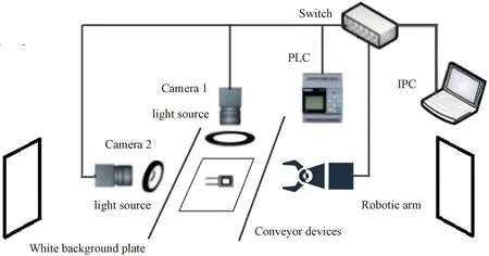
Fig.3 Diagram of the hardware structure of the detection system
The conveyor device consists of PLC and conveyor belts. The conveyor belts send the workpiece to be tested by the photoelectric switch, the PLC collects the photoelectric signal and controls the camera to take pictures, and the system judges whether the current workpiece is qualified or not and sends the result to the PLC. If the workpiece is qualified, the conveyor belt continues to run; if it is not qualified, the alarm is raised and the workpiece is taken away by the robotic arm.
The light source control system includes two LED lights and a switch. Two white LED ring lights provide shadow-free light, the top light source has an outer diameter of 220 mm and an inner diameter of 170 mm, and the side light source has an outer diameter of 180 mm and an inner diameter of 110 mm.
When building the hardware system, the light source, the workpiece, and the camera lens are kept perpendicular to the center, with a white background plate behind to avoid environmental interference. The distance between the light sources and the camera and the stator winding coil to be tested should meet the requirements of the production site. The hardware structure location diagram of the detection system is shown in Fig.4.

Fig.4 Hardware structure location diagram of the detection system
2 Research on Dual Region Algorithm for Online Vision Detection System
2.1 Lead paint stripped region detection algorithm
For the lead paint stripped region, firstly, the image is preprocessed to reduce and eliminate the noise interference caused by reflections and shadows as well as ambient light, and to enhance the contrast of the image. Secondly, feature-based template matching is used to locate the image and set up a reference coordinate system. Finally, Blob analysis is performed on the image to separate the object from the background using threshold segmentation and grayscale morphological operation. An improved Canny algorithm is used for lead edge detection.
2.1.1Imagepreprocessing
The illumination in the production environment varies due to weather and other reasons, and there are also noise disturbances e.g. light spots inside the image. Firstly, the image is adjusted to grayscale, and further expanded with a 3 × 3 square eight-neighborhood dilation of the structural elements and a 3 × 1 vertical three-element dilation, respectively. Secondly, the pixels are remapped using a grayscale transformation function to ensure that the grayscale values are similar for successive phases. Finally, median filtering is performed to further eliminate noise disturbances. The effect of image preprocessing is shown in Fig.5.
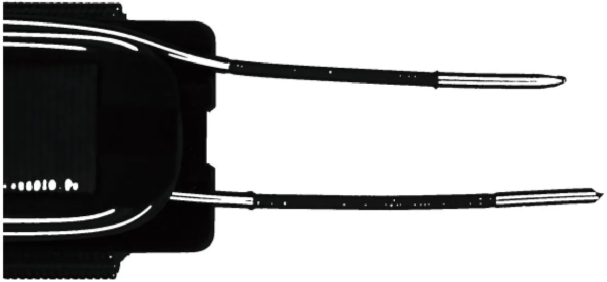
Fig.5 Effect of image preprocessing
2.1.2Templatematchingandpositioning
Template matching uses the sliding window principle to match the template on the target image[16]. The stator winding workpiece recess region is selected as the template by shielding both sides of the conveyor belt part in the image, which has obvious features and a relatively simple geometry. The template matching, region of interest (ROI) is shown in Fig.6(a), and the partial enlargement of the ROI is shown in Fig.6(b). The center of the image recess is found on the result of template matching for positioning, and the direction of axes x and y of the coordinate system after positioning is shown in Fig.6(c). If the template matching fails, the PLC controls the robotic arm to pick up the workpiece.
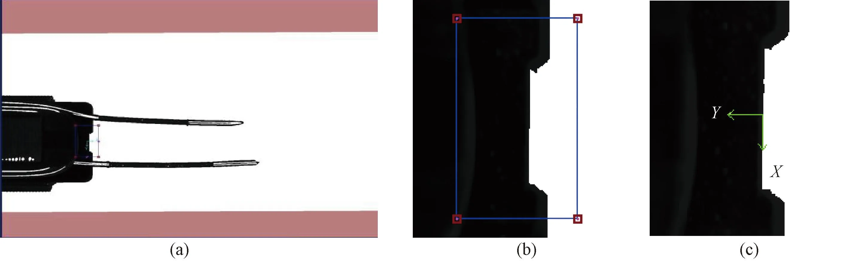
Fig.6 Effects of template matching and positioning: (a) template matching ROI; (b) partial enlargement of ROI; (c) coordinate system after positioning
2.1.3Blobanalysis
Blob analysis uses threshold segmentation to segment the target and background in the image, the connected region analysis for the target and the grayscale morphology algorithm to eliminate shadows within the reflective region. Due to the effect of light in different environments resulting in different gray values of the image, adaptive dynamic thresholding of the image is performed using the Otsu algorithm. The image after using threshold segmentation is shown in Fig.7(a), and the segmented image is processed for connected region analysis. The holes with smaller areas are filled and the gray-scale morphological erosion algorithm is used to enhance the feature values of the target, and the processing effect is shown in Fig.7(b).
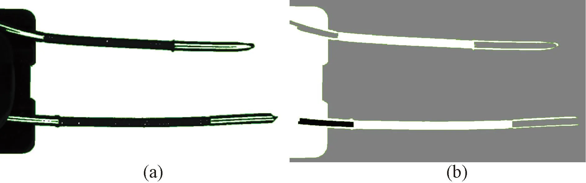
Fig.7 Effect of Blob analysis on lead region processing : (a) image segmentation; (b) connected region analysis
2.1.4ImprovedCannyalgorithmforedgedetectionofleadpaintstrippedregion
The Sobel algorithm and Canny algorithm with better accuracy are used for edge detection of the lead paint stripped ROI, and the detection results are shown in Fig.8.
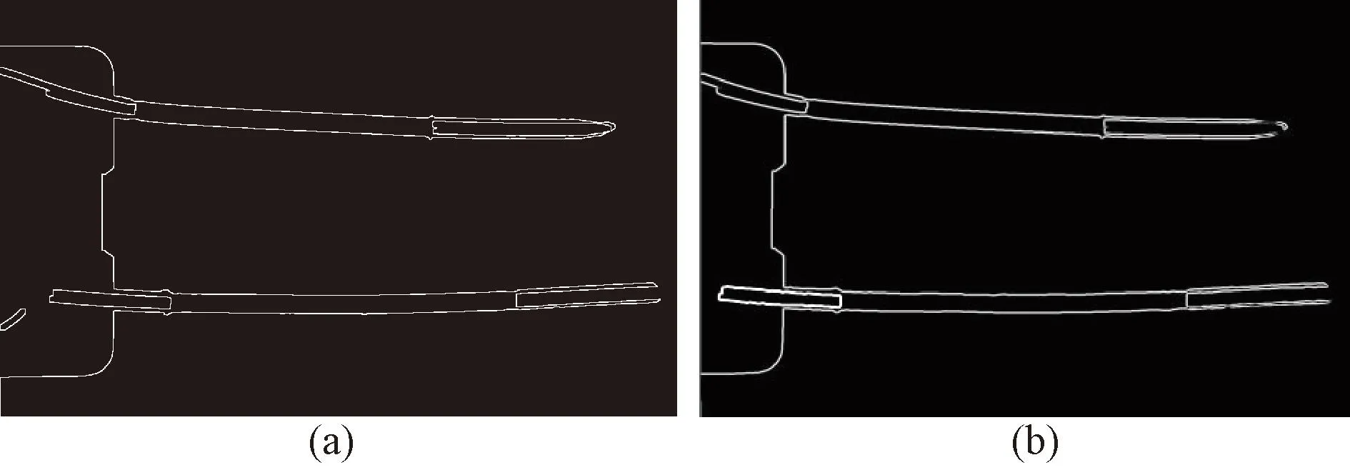
Fig.8 Detection effect of different algorithms : (a) Sobel algorithm; (b) Canny algorithm
The Canny algorithm is effective but time-consuming and does not meet the requirements for online detection. Since the lead detection of the workpiece requires only edge detection in the horizontal direction, there is no need to calculate the magnitude and angle in the vertical direction, and there is no need to query by angle for non-maximum suppression[17]. The simplified Canny algorithm calculates the second-order derivative only for the horizontal direction of the image lead region.
Since multiple edge pairs may be detected in the lead paint stripped region, which interferes with the detection of actual edges[18], the conventional Canny algorithm uses non-maximum suppression and high and low thresholding methods. The effect is susceptible to noise interference and requires repeated comparisons. The Canny algorithm is improved to use the expected length and contrast model to determine the final edge and reduce the algorithm time.
Firstly, the edge pairs are scored according to the difference between the expected length and the inspected length. According to the process parameters, the length of the paint stripped region is mostly 13-19 mm, and the desired lengthL0of the upper and lower stripping line is taken as its middle value of 16 mm. A high scorenfor the length of 0.75L0-1.25L0(12-20 mm) is given as
(1)
(2)
whereLis the actual inspection length. The edge pairs that score in the bottom 50% are excluded.
Next, the contrast model is used to find the final edge pairs, and the contrast thresholdTof the upper and lower leads is found:

(3)
In the original image grayscale histogramf(x,y), the images with contrast less than the thresholdTare excluded to obtain the new grayscale histogramg(x,y).The highest contrastCmaxis found out, and its corresponding edge is the final edge.Cmaxis shown as
(4)
Detection results of coil lead paint stripped region under the improved Canny algorithm are shown in Fig.9. For 10 groups of workpieces, each group does 50 detections. A comparison of the detection time of the three algorithms is shown in Table 1. As can be seen from Table 1, the improved Canny algorithm reduces the time by more than half compared to the previous one, significantly improving the detection efficiency of the system.
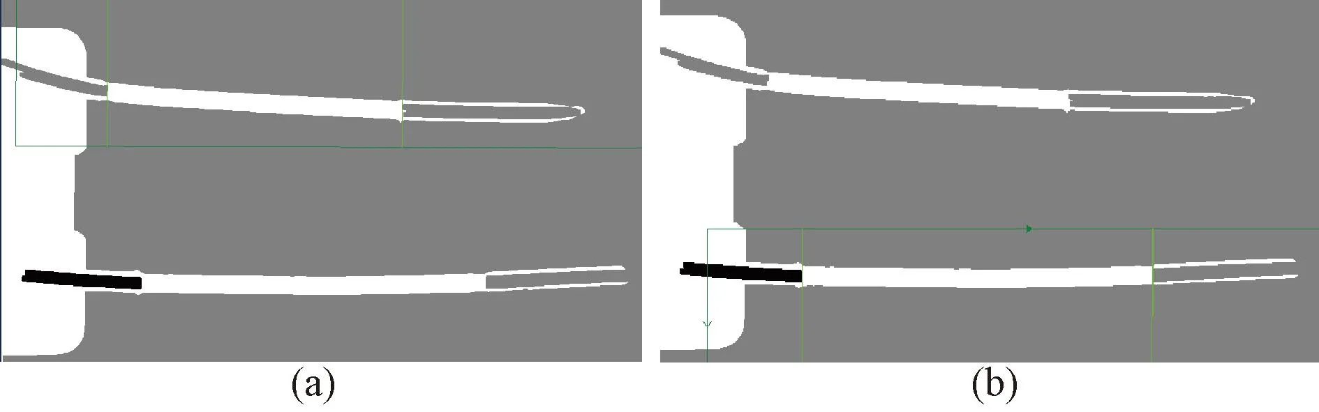
Fig.9 Detection results of coil lead paint stripped region under improved Canny algorithm : (a) upper lead; (b) lower lead
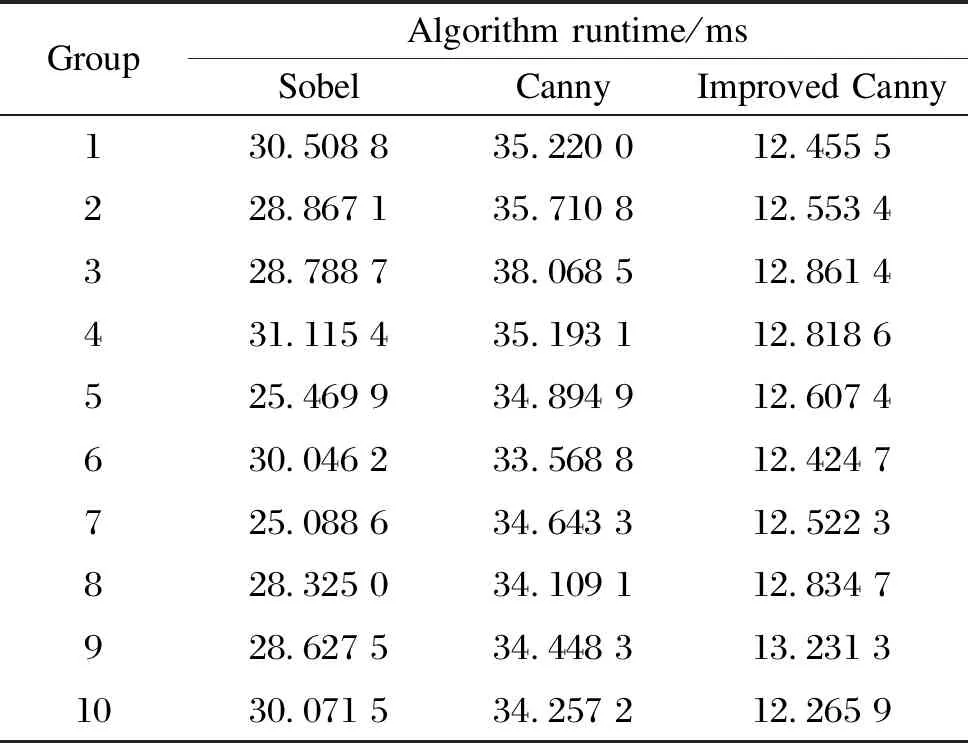
Table 1 Comparison of the detection time of three algorithms
2.2 Coil region winding wires cross feature detection algorithm
For real-time detection of coil winding wires cross feature, a single-stage deep learning target detection algorithm of the YOLO series is used to extract features and predict the classification and localization of targets by convolutional neural networks. The object detection task is treated as a regression problem, and the two phases of candidate region and detection are combined into one[19]to improve detection efficiency and reduce time.
YOLO divides the input image intoS×Sgrid cells, and if the center of an object is in that grid, then the grid predicts the objects in it[20]. The prediction yields the output feature dimensionS×Sand the depth dimensionB×(5 +C), whereSis the number of grids after image division,Bis the number of bounding boxes to be predicted for each grid andCis the number of categories of bounding boxes. Then the redundant windows are removed by non-maximum suppression for the previous inference. Each bounding box predicts five values for the center position coordinatesxandyof the box, the widthwand heighthof the box, and the targetivity score.
Among them, YOLOv5 uses an adaptive anchor frame that can be selected from YOLOv5s, YOLOv5m, and YOLOv5l weight types, and its model selection and training speed are superior compared to the previous ones[21]. Using the YOLOv5 algorithm for the detection of winding wires cross features, the YOLOv5 backbone feature extraction network uses a C3 structure, which brings a large number of parameters and a slow detection speed, so the application is limited. For industrial assembly lines, a low latency accurate and fast model with light weight is needed to make the detection of parts as fast as possible. In this paper, the backbone feature extraction network of the YOLOv5-5.0 version is replaced by the lighter ShuffleNet V2 network[22], the comparison of YOLOv5-5.0 and ShuffleNet V2-YOLOv5 is shown in Table 2. It can be seen that there is a significant reduction in the number of parameters for each part module, and there is one less layer of network modules after the lightweight.
Original images of 910 stator winding coils are enhanced by translating and rotating to obtain 1 800 images (1 000 of them are qualified and 800 are unqualified). The dataset is produced, and the qualified workpieces are marked as “Accept”, and the unqualified workpieces are marked as “Reject”. The deep learning environment is configured using the Python machine learning library PyTorch 1.9.0, the Python 3.7 programming language, CUDA 11.1 computing architecture, and the computer graphics card model NVIDIA GeForce RTX 3050.
YOLOv5s, YOLOv5l, and ShuffleNet V2-YOLOv5s weight models are selected for dataset training. The input image size is 640 pixel× 640 pixel, the ratio of the training sets and test sets is 8∶2, the parameter epochs are set to 200 generations, and the batch size is 4. A comparison of parameters after training of the dataset under different weight models is shown in Table 3. The floating point operation speed (GFLOPs) of the lightweight model is significantly reduced to 2.6, which makes the training time shorter. The training time for this dataset is about 16 h for ShuffleNet V2-YOLOv5s, 21 h for YOLOv5s, and 27 h for YOLOv5l.

Table 2 Comparison of module parameters between YOLOv5-5.0 network and ShuffleNet V2-YOLOv5 network
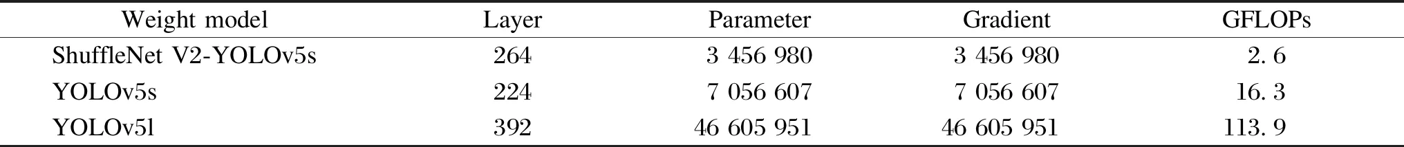
Table 3 Comparison of parameters after training of the dataset under different weight models
The evaluation metrics of the training results under different weight models are shown in Fig.10. From Fig.10, it can be seen that the ShuffleNet V2-YOLOv5s model does not differ much from the other two models in terms of the performance of mAP, precision and recall on this dataset, but performs well in terms of obj_loss.
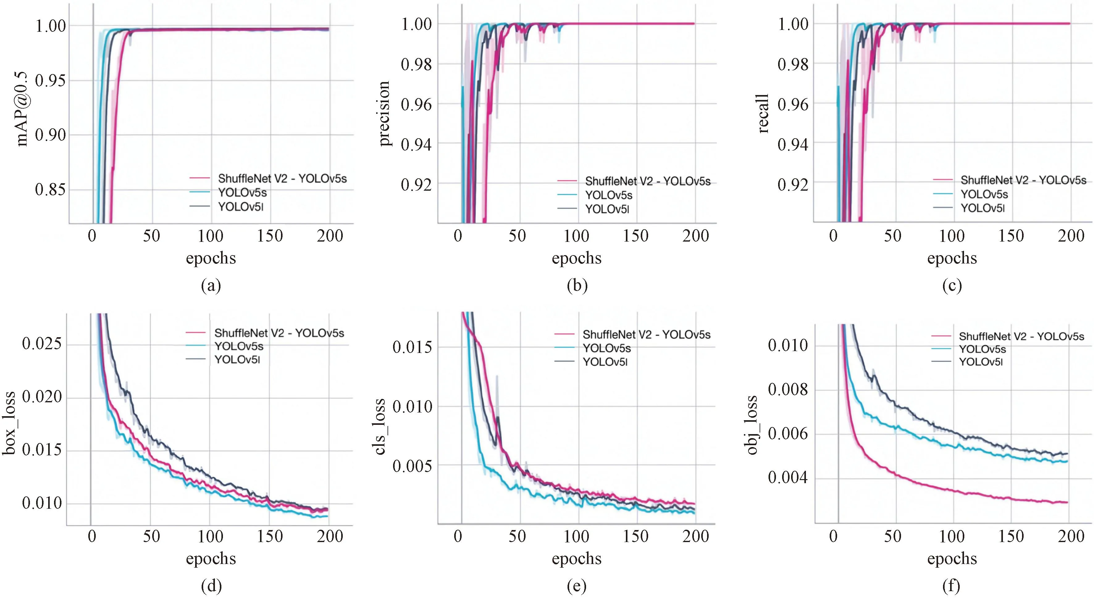
Fig.10 Evaluation metrics for training results of models with different weights : (a) mAP@0.5; (b) precision; (c) recall; (d) box_loss; (e) cls_loss; (f) obj_loss
ShuffleNet V2-YOLOv5s model is used to train the dataset, and the generated best.pt file is selected as the weight file for the new prediction detection for the stator winding coil workpieces on the assembly line. Eight representative coil workpieces (one qualified workpiece and seven unqualified workpieces with different defects) are selected for the prediction result presentation, as shown in Fig.11. The category of workpieces is correctly determined, and the confidence of each workpiece category is above 0.90, which meets the detection requirements.

Fig.11 Prediction results for typical workpieces : (a) qualified workpiece; (b)-(h) unqualified workpieces
3 Experiment and Analysis of Online Vision Detection System
In this study, the software interface of the detection system based on.Net Framework is developed in Visual Studio 2015 environment on Win10 using C# language. It includes camera control, image processing setup, data analysis, YOLOv5 inspection, and remote communication modules. The main interface displays the processed images, measured data values and workpiece discrimination results, and completes the control and debugging of the detection system, as shown in Fig.12. The introduction of each module is as follows.
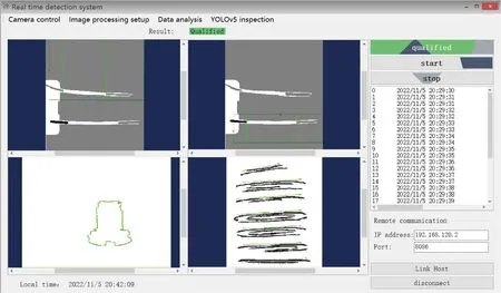
Fig.12 The main interface of the system software
1)Camera control module. It includes the camera hardware and software trigger mode. The software trigger mode is divided into single acquisition and continuous acquisition, the continuous acquisition controls the camera to take pictures simultaneously by setting the interval time. The system sets four time intervals, 500 ms, 750 ms, 1 s and 3 s.
2)Image processing setup module. The main function of this module is to select algorithms, cameras, or image files used for lead region detection, as well as real-time editing of files.
3)Data analysis module. The main function of this module is the real-time display of lead detection data, and the clearing and exporting of the detection data. After the detection is finished, it is saved as a.csv file, and the mean and variance of the data are calculated,etc.The average detection time of the workpiece, the number of acquisitions, the number of passes, and the pass rate are given.
4)YOLOv5 detection module. The main function of this module is to display detection images and results of the detection of winding cross features in the coil region.
5)Remote communication module. The main function of this module is to send the results to PLC through TCP/IP using Socket after the detection is finished. The system sends the results of “Accept”, “Reject”, or “Retry to PLC” in the form of byte arrays, and PLC completes the subsequent control operation according to the results.
An experimental platform is built to test the online vision detection system for stator winding coil. Three detection aspects, namely template matching, coil lead region, and coil winding cross feature, are classified and counted for the system’s accuracy test. The 1 000 collected pictures under different light intensities in daily production are tested. Statistics of qualified results for stator winding coil workpieces are shown in Table 4. The display interface of data results for the coil lead region is shown in Fig.13.
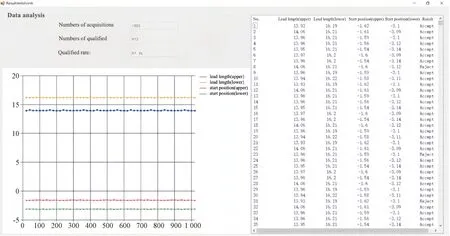
Fig.13 Display interface of data results for coil lead region
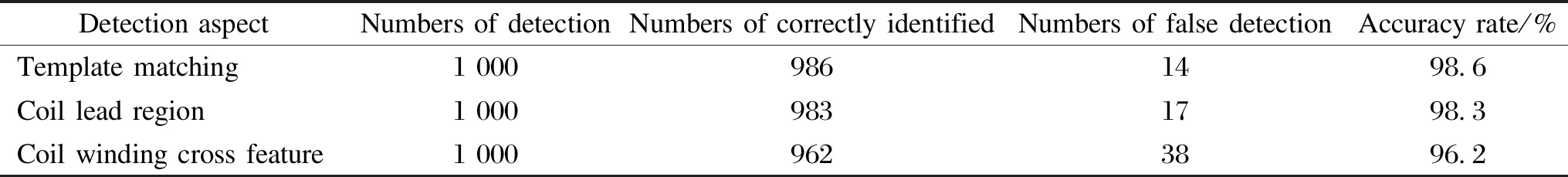
Table 4 Statistics of qualified results for stator winding coil workpieces
ShuffleNet V2-YOLOv5s model is used to train the dataset and the generated best.pt file is selected as the new weight for the detect file and converted to Open Neural Network Exchange (ONNX) file format. The ONNX deep learning model is invoked in the detection system to detect the stator winding coil workpieces on the assembly line. For eight representative groups of coil workpieces (one group of qualified workpieces and seven groups of unqualified workpieces with different defects), 100 tests are performed for each group of winding cross features, and a total of three tests are done. The average time for workpiece detection under the ShuffleNet V2-YOLOv5s model is shown in Table 5. From Table 5, it can be seen that it has a very fast speed for detection, and the average detection time per image does not exceed 30 ms.
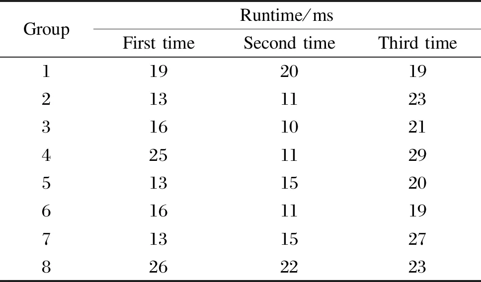
Table 5 Average time for workpiece detection under ShuffleNet V2-YOLOv5s model
Ten groups of workpieces of the stator winding coils of the same batch model motor are detected under different light intensities, with 700 sample images for each group. The detection results are shown in Table 6. As can be seen from Table 6, the workpiece discrimination results are judged by the combination of image processing and YOLOv5 results, the discrimination results are consistent with the actual results, and the test system has good stability. The average detection time for a workpiece to complete image acquisition, image processing, and communication does not exceed 300 ms, meeting the requirement that the average detection time of each workpiece does not exceed 500 ms. After testing, the accuracy of the workpiece qualified discrimination is 96.2%, and the data acquisition, processing, and communication meet the design requirements.
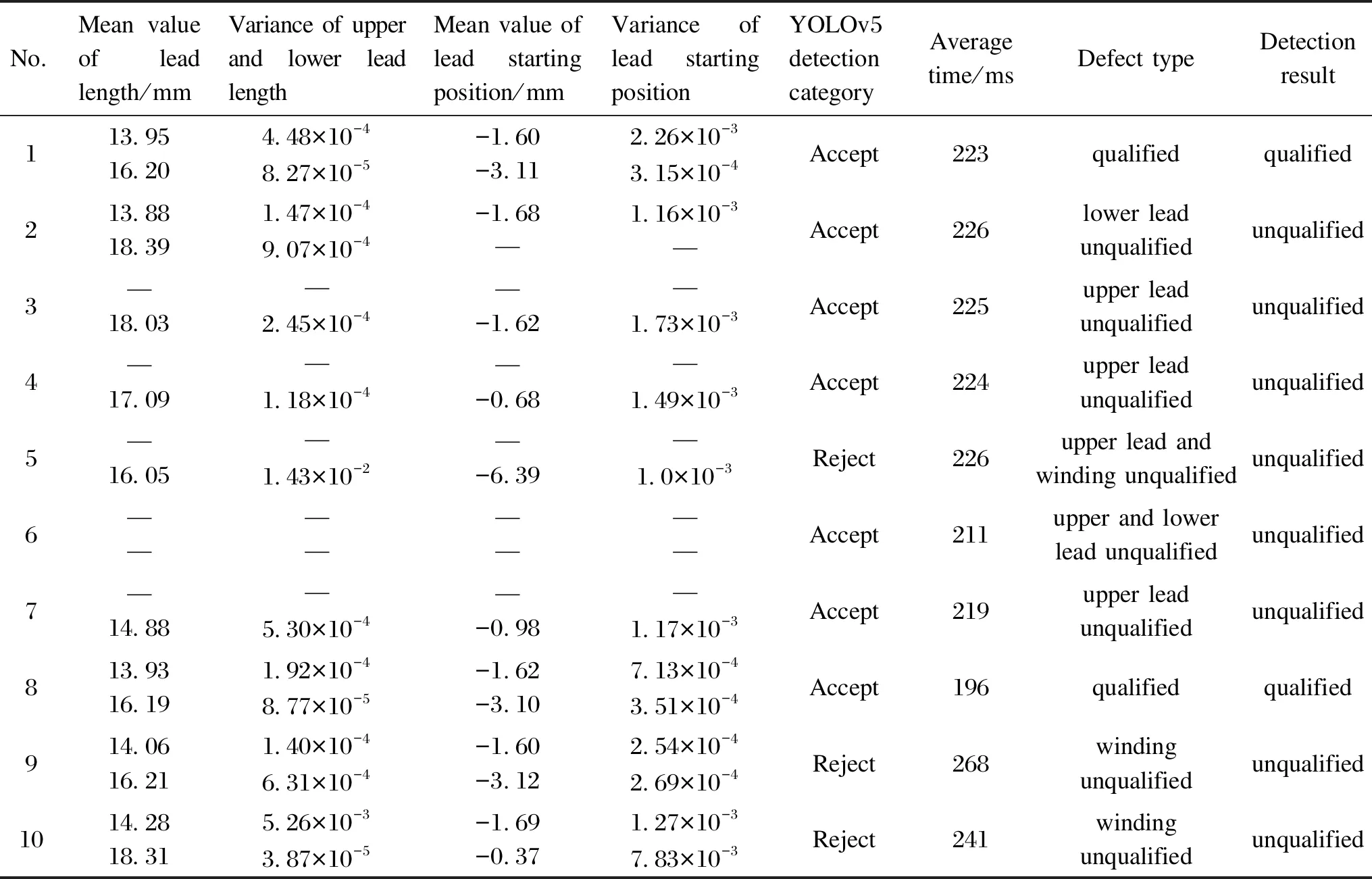
Table 6 Detection results of 10 groups of workpieces under different light intensities
4 Conclusions
The quality of the stator winding coil has an important impact on motor safety. In this study, by analyzing the types and specific characteristics of defects in the leads and winding region of stator winding coils, the online vision detection platform was designed. The image processing and ShuffleNet V2-YOLOv5s model were used to detect whether the lead region of the winding workpiece was paint stripped, whether the starting position of the leads stripped was qualified, whether the turns of coil winding were too small or whether the coil winding was deformed. By using the image processing and ShuffleNet V2-YOLOv5s model, the real-time detection requirement was achieved. The human-machine interface was designed to realize the functions of automatic detection and identification, qualified information display, and data statistical calculation. The accuracy of qualified discrimination and detection time of the workpiece were tested. The test results showed that the accuracy of qualified discrimination reached 96.2%, and the average time of individual workpiece detection was about 300 ms, among which the detection time of YOLOv5 for individual workpiece winding cross features was less than 30 ms, which met the requirement of detection on the industrial assembly line. The detection system has positive application value in actual production applications, effectively improving the detection accuracy of stator winding coil, and has certain application value and research significance for coil qualification detection.
杂志排行

Journal of Donghua University(English Edition)的其它文章
- Laser-Induced Graphene Conductive Fabric Decorated with Copper Nanoparticles for Electromagnetic Interference Shielding Application
- Toughness Effect of Graphene Oxide-Nano Silica on Thermal-Mechanical Performance of Epoxy Resin
- Photoactive Naphthalene Diimide Functionalized Titanium-Oxo Clusters with High Photoelectrochemical Responses
- Preparation and Thermo-Responsive Properties of Poly(Oligo(Ethylene Glycol) Methacrylate) Copolymers with Hydroxy-Terminated Side Chain
- Synthesis, Characterization and Water Absorption Analysis of Highly Hygroscopic Bio-based Co-polyamides 56/66
- Clothing Parsing Based on Multi-Scale Fusion and Improved Self-Attention Mechanism