Optimization design of conical reaction teeth of shear wave vibroseis vibration plate
2023-12-06WANGHongxiangDULizhiandSUNZhen
WANG Hongxiang, DU Lizhi* and SUN Zhen
1. College of Construction Engineering, Jilin University, Changchun 130026, China;
2. China Water Northeast Survey, Design and Research Co., LTD, Changchun 130061, China
Abstract: The vibrator plate is the link between the vibroseis vehicle and the earth, as well as the core component of the vibrator vehicle.In this paper, the coupling effect between the vibrator plate and the earth is analyzed from two aspects of reaction tooth arrangement and reaction tooth conical angle, and three groups of experimental models are optimized and designed.The model construction and numerical analysis of the shear wave vibroseis vibrator plate are carried out with ANSYS software.The motion law between the vibration plate and the earth at work was studied, the strain energy of the three experimental models in operation, the maximum displacement of particle at the same position and other reference indices were compared and analyzed, with 28 conical reaction teeth were arranged on both sides.The coupling effect between the vibration plate and the earth was best when the tooth angle was 60°.Compared with the toothless vibration plate, the energy efficiency is improved by about 20%, and the coupling effect between the vibrator plate and the earth is effectively enhanced.It is found that the coupling effect is enhanced through increasing the number of reaction teeth of the vibration plate by increasing the coupling area between the vibration plate and the earth.
Keywords: shear wave vibroseis; vibration plate; conical reaction teeth
Introduction
In recent years, many major breakthroughs have been made in shear wave seismic exploration.The shear wave vibroseis is widely used in shallow seismic exploration due to its feature of short wavelength propagation distance, through which faults in strata can be well identified (Sun, 2022; Duet al., 2015;Chenet al., 2020; Ni, 2012).Its position in the field of exploration is gradually improving, and it has become urgent to study and develop new functions of shear wave vibroseis.This research is based on a portable self-driven hydraulic vibroseis vehicle independently developed by Jilin University, which can be applied to seismic exploration in mountainous areas (Liang,2022).Compared with the normal model, this kind of vibrator vehicle is smaller, lighter in weight and convenient in operation.
The vibroseis vehicle is mainly composed of the hydraulic drive system of the source vehicle and the source system, in which the vibration plate is the main component of the source system, and the vibration plate is the key medium between the vibroseis vehicle and the earth during operation (Ou, 2019; Maet al.,2015).However, it is found in the concrete experiment that the poor coupling between the conventional plate and the earth directly affects the quality and effect of the vibration signal in the practical work of the S-wave vibroseis, leading to the low energy transfer efficiency between the plate and the earth.
Based on the fact that the bottom plate of the improved shock plate is a conical reaction tooth, this paper designs the tooth arrangement and tooth angle.Through numerical simulation, ANSYS software is used to model the shear wave vibroseis shock plate and conduct numerical analysis (Hu, 2009; Huanget al., 2016).Moreover, simulation experiments are conducted on the successfully established coupling model so as to design a vibration plate model with better performance (Huanget al., 2019; Xuet al.,2001; Tao, 2001; Yeet al., 2020).
This experiment is of great significance for improving the performance and working efficiency of shear wave vibroseis vehicle and enhancing the coupling of shock plate (Haoet al., 2021; Xueet al.,2010; Liang, 1986).It establishes a good foundation for better improving the geological exploration capability of vibroseis vehicle and provides theoretical basis for further research on other influencing factors of conical reaction teeth.The purpose of this paper is to improve the energy utilization rate of vibroseis vehicle by improving the coupling between vibration plate and earth (Denget al., 2015; Huanget al.,2017).
1 Shear wave vibroseis vibration plate conical reaction tooth design
1.1 Vibration plate design
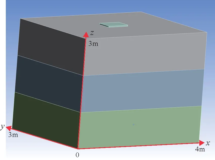
Fig.1 Vibration plate and earth model
In order to study the influence of vibration plate bottom plate style on coupling and further improve the energy utilization rate of vibrator vehicle, this paper designed a cone with conical reaction tooth structure, and arranged it at the bottom of the vibration plate according to the form of matrix.Finally, type I: uniform arrangement type; type II: the closearranged type on both sides were the experimental objects of this study.Subsequently, in order to explore the influence of conical angle of reaction teeth on coupling, conical reaction teeth with 30°, 45° and 60°tooth angles with the same tooth height and different tooth undersides were designed for conical angle.Finally, the design was optimized through numerical simulation.
1.2 Construction of numerical model
This experiment adopts orthogonal design and controls variables to design three groups of comparison experiments aiming at tooth angle, tooth number and tooth arrangement.Specific research contents are as follow:

Fig.2 45° conical plate teeth
(1) The experimental comparison of 16 conical teeth with 60° angle uniform arrangement and 28 conical teeth with 60° angle uniform arrangement, that is, the coupling characteristics of the same reaction tooth angle, different number and the same arrangement mode are studied.
(2) The experimental comparison of 28 conical teeth with 60° angle uniformly arranged and 28 conical teeth with 60° angle on both sides of the arrangement,namely the same reaction tooth angle, the same number of teeth, different arrangement of the excitation plate coupling characteristics.
(3) The experimental comparison between 28 conical teeth with 60° angle and 28 conical teeth with 45° angle and 28 conical teeth with 30° angle was carried out, that is, the coupling characteristics of excitation plate with different reaction tooth angles,and based on the same number of teeth and the same arrangement mode were studied.
The three groups of experiments are in a progressive relationship.By studying the coupling effect between the conical reaction teeth of the vibration plate and the ground in different numbers, different arrangements and different tooth angles, and based on the experimental data obtained by referring to the evaluation index, under comprehensive analysis of the three situations, we finally get the type of vibration plate with the relatively best coupling effect with the earth of the conical reaction teeth.
Two kinds of materials are involved in the simulation, which are the soil forming the ground and the structural steel forming the shock plate.The specific parameters are shown in Table 1 and Table 2.
Then the Prince seized the girl s hand and cried out, This is the Princess Hyacinthia! You re right again, said the Magician in amazement37; but I ve still another task for you to do
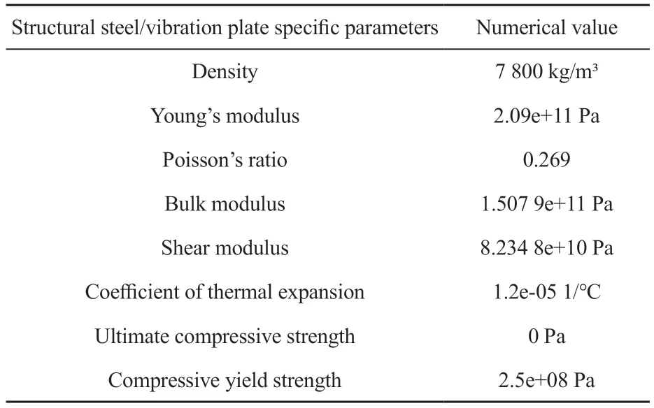
Table 1 Parameters of plate model
In the early construction of the model, in order to simulate the exciting force exerted by the heavy weight on the vibration plate as much as possible, four ImprintFaces were added to the authors heavy weight was: To create a face where one entity intersects another, to impose constraints or loads on parts of the plane, we need to use the ImprintFaces command to facilitate local force loading.The force to be applied to the vibration plate has two parts, one is the downforce of the hammer to the vibration plate, the other is the transverse dynamic change of the sine force.The total size of the downforce is 3 000 N, so the force to be applied on each impression surface is 750 N.A transverse dynamic sinusoidal force is applied outside the weight.The formula of the force is:
It is a segmented diagram of the dynamic sinusoidal force during the operation of the model (Fig.3).In addition, a downward vertical force of gravity is applied to the system as a whole, with a magnitude of 9.81 m/s squared.Fixed supports are applied all around the ground.
The above are the specific parameters of this experiment.
In order to better distinguish the advantages and disadvantages of the three experimental models,two groups of evaluation indices are involved in this experiment, which are respectively the motion intensity of ground particles in thexdirection and the decoupling degree of vibration plate deformation.Comprehensive analysis of the experimental results through the selected evaluation indices can effectively improve the accuracy of the experiment.

Fig.3 Sectional diagram of horizontal force
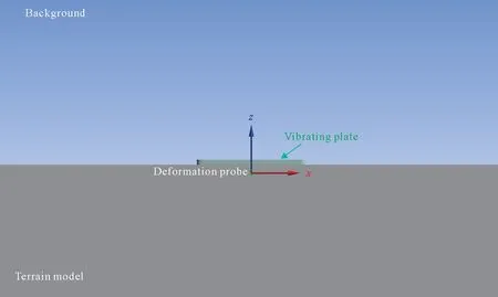
Fig.4 Schematic diagram of the deformed probe
Fig.4 shows the motion intensity of the geodetic particle at the deformation probe in thexdirection.The displacement and time curve of the geodetic particle in thexdirection can be obtained by extracting the displacement of the geodetic particle at the position of the deformation probe in the figure for quantitative analysis.The amplitude of the geodetic particle coordinates is the motion intensity of the geodetic particle in thexdirection.In the process of energy transfer,since the horizontal force is in thexdirection, the motion intensity of the other two directions is not considered when observing the numerical simulation results.The motion intensity of the earth particles in thexdirection can be judged by the amplitude of the displacement image.The larger the amplitude,the higher the motion intensity, and the better the excitation effect of the source and vibration plate.
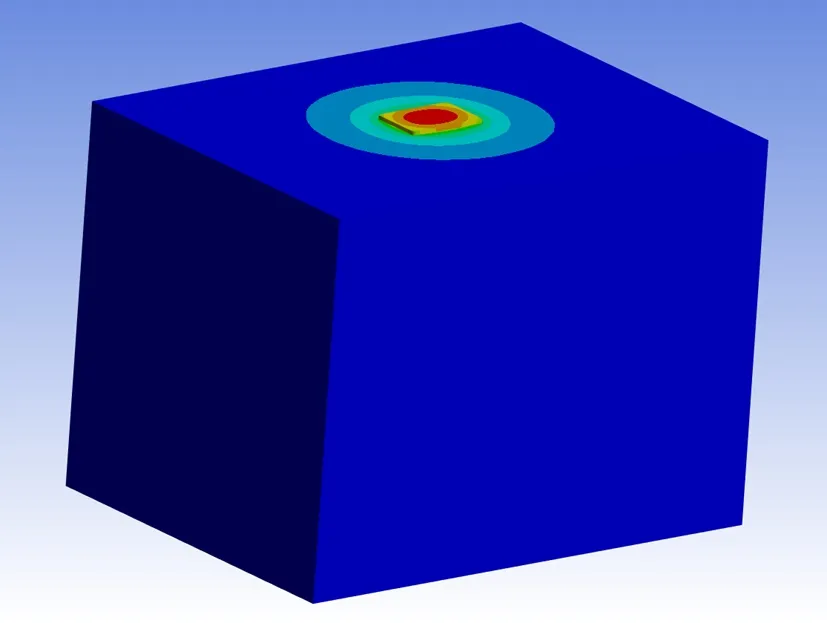
Fig.5 Deformation schematic overall picture
Through the graph of model grid division, it can intuitively judge the change of the degree of decoupling when one of the influencing factors of the shock plate is changed.Meanwhile, according to the conclusion that the less the degree of decoupling,the better the coupling, the best range of influencing factors can be obtained.The deformation diagram is shown in Fig.5 and Fig.6.

Fig.6 Deformation diagram of vibration plate
The energy transfer rate of the vibration plate mainly refers to the ratio of the energy transmitted by the focal system to the earth to the total energy output of the vibration plate during the operation of the vibration plate.In the comparison experiment,the strength of the energy transfer energy of different vibration plates can be compared by the energy transfer rate.The more energy the excitation plate spills during operation, the smaller the corresponding detection depth is, and the bigger it is on the contrary.Therefore,the energy transfer rate of vibrator plate is one of the important evaluation indices of vibroseis performance.
2 Numerical simulation results and analysis
The three groups of comparison experiments designed in this paper have the same experimental simulation process, data extraction and analysis methods in addition to the different styles and arrangements of the bottom plate of vibration plate.Therefore, the third group of experiments are selected to demonstrate the coupling characteristics of the vibration plate with different reaction tooth angles, the same number of teeth and the same arrangement.
Fig.7 to Fig.9 show, they are the experi-mental objects of the third group of experiments.
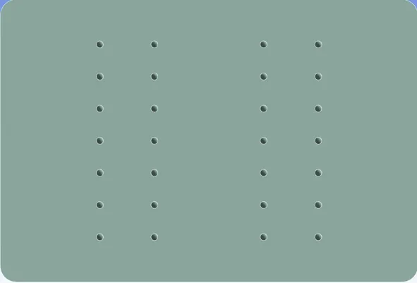
Fig.7 Conical tooth layout on both sides at 30° angle

Fig.8 Conical tooth arrangement on both sides at 45° angle

Fig.9 Conical tooth layout on both sides at 60° angle

Fig.10 Bilateral arrangement of 28 conical teeth at 30° angle (workbench motion intensity output image)
Fig.10 is the variation diagram of the motion intensity of ground particles in thexdirection at the deformation probe of the vibration plate earth model with a tooth angle of 30° output in ansys software.The figure is the time variation curve of the motion intensity of ground particles extracted the same position.
Fig.11 is a comparison diagram of the motion intensity of the output data of the three models drawn under an axis.It can be intuitively judged that the energy transfer effect of 28 excitation plates arranged on both sides of the 60° cone is better based on the average peak value of the motion curve in Fig.11.
Fig.12 is the strain energy change diagram output by ansys software of the earth model of the vibration plate with a tooth angle of 60°.The figure is the energy change curve contained in the deformation of the vibration plate when the vibration plate changes with time during operation.
Table 3 and Fig.13 are the comparison diagram of the maximum strain energy of the three models(the maximum strain energy is the difference between the average peak value in operation and the baseline before operation) drawn under an axis.As the deformation degree of the vibration plate increases, the energy contained in the vibration plate increases, and the coupling effect between the vibration plate and the earth becomes worse.Therefore, it can be seen from the image that the strain energy of the excitation plate is the maximum at 30°, and the coupling effect with the earth is the worst.The deformation degrees of 45°and 60° are similar, and the coupling effects with the earth are better.

Fig.11 Comparison of motion intensity of earth particles

Fig.12 Bilateral arrangement of 28 conical teeth at 60° angle (workbench strain energy output image)

Table 3 Comparison of strain energy for 28 reaction teeth arrangment on both sides at different angles (unit: mJ)
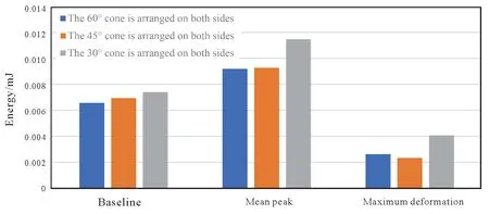
Fig.13 Comparison of strain energy for 28 reaction teeth arrangement on both sides at different angles
Comparison of particle displacement data at representative time points is shown in Table 3 and Fig.14.
Numerical simulation analysis results are shown in Fig.14 and Table 4, four representative time nodes are selected, and through numerical and image comparative analysis, it can be intuitively judged that under the same arrangement mode and number, the coupling effect between the vibration excitation plates arranged on both sides with a tooth angle of 60° is the best.Moreover, by comparing the three groups of vibration excitation plates, as the tooth angle of reaction teeth increases, the coupling effect between the shock plate and the earth gradually becomes better in the high frequency band.

Table 4 Data of fixed point displacement on both sides of 28 reaction teeth at different angles (unit: nm)
Through the same experimental method, numerical simulation analysis results of Experiment 1 and Experiment 2 can be obtained:
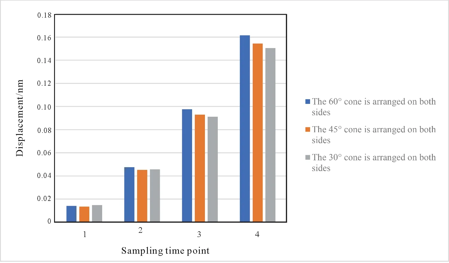
Fig.14 Comparison of fixed point displacement for 28 reaction teeth on both sides at different angles
(1) Under the same tooth angle and arrangement mode, the coupling effect between the vibration plate and the earth with 28 conical teeth uniformly arranged is better than that with 16 conical teeth uniformly arranged.
(2) Under the same tooth angle and number conditions, the coupling effect between the vibration plate arranged on both sides and the earth is better than that of uniform arrangement.
Comprehensive analysis of the above three groups of data shows that when the number of conical teeth is 28 and the two sides are concentrated, the energy transferred to the earth is the largest, and the deformation of the earth particles is the largest,indicating that in this case the coupling degree between the vibration plate and the earth is the best, and with the increase of the reaction tooth angle, the output energy of the vibration plate with different tooth angles is similar in the early 1s low frequency excitation.In the subsequent excitation process, the coupling effect between the high frequency vibration plate and the earth becomes better.
3 Conclusions
In this paper, basis on the analysis shear wave vibroseis vibration plate conical reaction teeth, the layout of reaction teeth and tooth angle of the simulation, the author design several groups of different parameters of the earth-vibration plate model, using the control variable method, according to the output of workbanch image and data screening, find the data corresponding to the evaluation index summarized.And from that,the following sets of conclusions:
(1) For conical reaction teeth, under the same tooth angle and arrangement mode, 28 conical teeth uniformly arranged is better than 16 conical teeth uniformly arranged, and the coupling effect with the earth is better.It is found that properly increasing the number of reaction teeth on the vibration plate can effectively improve the coupling area between the vibration plate and the earth, thus improving the coupling effect.
(2) For conical reaction teeth, under the same tooth angle and number of reaction teeth, 28 conical teeth are arranged on both sides is better than uniform arrangement, and the coupling effect with the earth is better.
(3) For conical reaction teeth, the coupling effect of vibration plate with conical reaction teeth angle of 60° is better than 45°, and the coupling effect of tooth angle of 45° is better than 30° under the condition that tooth height, number and arrangement are unchanged.
In this paper, the tooth angle and arrangement of the conical reaction teeth of the vibration plate are studied, so that the bottom design of the vibration plate can be optimized more carefully, so as to improve the energy transfer rate between the shear wave vibroseis vibration plate and the earth.
杂志排行
Global Geology的其它文章
- Exploring the first occurrence of Scincomorpha lizard from Nenjiang Formation (lower Campanian) of Jilin, Northeast China: a follow-up study
- Least-squares reverse time migration in visco-acoustic media based on symplectic stereo-modeling method
- Characteristics and identification of weathering crust of Pennsylvanian volcanic rocks in Shixi area, Junggar Basin
- Geochemical characteristics of temperature and pressure of Paleozoic reservoir fluid inclusions in Xuanjing region,Lower Yangtze area
- Change of cultivated land area and effect on ecosystem service in black soil region in Northeast China:a case study of Lishu County, Jilin Province
