Developing time‑of‑flight polarized neutron capability at the China Spallation Neutron Source
2023-12-05LongTianAhmedSalmanChuYiHuangYuChenDongFanYeZeCongQinWolfgangKreuzpaintnerJunPeiZhangTianHaoWangXinTong
Long Tian · Ahmed Salman · Chu‑Yi Huang,3 · Yu‑Chen Dong,3 · Fan Ye,4 · Ze‑Cong Qin ·Wolfgang Kreuzpaintner · Jun‑Pei Zhang · Tian‑Hao Wang · Xin Tong
Abstract Polarized neutrons play an indispensable role in neutron scattering research and have been incorporated into various neutron diffractometers and spectrometers.Recognizing the importance of polarized neutrons, the China Spallation Neutron Source(CSNS) has dedicated resources for developing its own capabilities for polarized neutron techniques.Hence, a polarized neutron development platform was allocated to the BL-20 beam port at CSNS for the purpose of facilitating new technological developments and calibration of instruments.Here, we report the progress we have made in terms of using the established development platform at BL-20, including the characterization of neutron spin filter cells manufactured at CSNS, the calibration of self-developed polarized neutron instruments, performance of the polarized neutron technique applied to beamlines,and associated simulation work for beamline magnetic field environments.These results demonstrate the capability of the CSNS to develop time-of-flight polarized neutron instruments and techniques in-house, which will be incorporated into the construction of CSNS neutron beamlines.
Keywords Polarized neutron · Polarization analysis · Neutron instrumentation
1 Introduction
By taking advantage of the fact that neutrons are uncharged,yet possess magnetic moments, the polarized neutron technique has been widely applied to various types of neutron beamlines in major neutron sources worldwide.Applications of polarized neutrons stand out in research involving magnetic structures and excitations and are therefore prevalent in most neutron scattering experiments [1–4].By utilizing polarized neutron techniques in diffraction research, contributions from nuclear, magnetic, and incoherent scattering can be identified, allowing the information about the magnetic structure obscured by other signals to be explicitly separated, as demonstrated by applications at the Institut Laue-Langevin (ILL) D7 and the High Flux Isotope Reactor(HFIR) HB-1 [5–7].In neutron spectroscopy experiments,neutron polarization analysis methods are used to distinguish magnons from phonons to study spin wave mechanisms.Typical applications of the polarized neutron spectrometry are performed at the ILL THALES and IN22 beamlines[8, 9].For mesoscale and large-scale structural studies, the polarized neutron technique is commonly applied to neutron reflectometry and small-angle neutron scattering (SANS)beamlines, such as the beamlines of the Heinz-Maier-Leibnitz Zentrum (MLZ) KWS-1 and National Institute of Standards and Technology (NIST) NG-1 [10, 11].
The China Spallation Neutron Source (CSNS), designed as a large-scale multidisciplinary neutron source, currently operates with 100 kW proton beam power, generating a stable neutron beam with a high flux of neutrons.The CSNS provides a powerful and comprehensive research platform for many frontier disciplines involving the study of the structures and dynamics of various material systems [12–14].Great demand exists for the capability to supply polarized neutrons to meet different research requirements at CSNS,including studies of nanomagnetic materials on its very small-angle neutron scattering spectrometer [15, 16], as well as magnetic dynamics studies of materials on the directgeometry polarized neutron inelastic scattering spectrometer[17, 18].In this case, in-house research and development(R& D) work on the polarized neutron technique is urgently needed for CSNS because commercially available polarized neutron components are often inadequate for customization,particularly for complex neutron beamline applications.
R &D in scientific instrumentation is crucial for maintaining the long-term performance and capabilities of a neutron beamline.Therefore, dedicated test beamlines are commissioned at neutron facilities, such as the NOBORU beamline at J-PARC in Japan [19], the TBL beamline at the European Spallation Source (ESS) in Sweden [20], and the HB-2D and CG-4B beamlines at HFIR in the USA.These beamlines support studies such as detector trials, polarized neutron imaging tests, examinations of instruments developed inhouse, and verification of new techniques.The development of key instruments on test beamlines, including the calibration of3He spin-filtering cells, detector tests, and examination of the chopper design [20–22], indicates the importance of development tests in the smooth commissioning of such instruments or techniques.In addition, these beamlines have contributed to advanced neutron research [23, 24].
The primary R &D goal for polarized neutrons at CSNS is to generate and manipulate polarized neutrons in a selfsufficient way.Significant progress has been made in this area, including the in-house development of3He neutron spin filter (NSF) systems, neutron spin flippers, and customized guide field systems.As a newly commissioned neutron source, CSNS also takes advantage of the opportunity to open up novel neutron experimental methods and further promote research on neutron methodology.To satisfy the in-house requirements for polarized neutron development, as well as to explore new techniques, time-of-flight polarized neutron development at CSNS aims to achieve quantitative analysis of neutron polarization across a wide range of wavelengths.Such work will be conducted under various beamline configurations along with customized simulations of the magnetic field environment and neutron polarization, which are expected to improve our understanding of the performance of polarized neutron setups.
In this paper, we report the performance of the polarized neutron technique under different combinations of customized polarized neutron instruments at the neutron technology development beamline (BL-20) at CSNS, as well as the capability of simulating the magnetic field environment and neutron polarization of the beamline, indicating that CSNS have the ability to generate and manipulate polarized neutron beams with high neutron polarization and transmission over a wide range of neutron wavelengths and can meet the needs of various neutron experiments.
2 Setup of the polarized neutron experiment platform at CSNS
Test experiments using polarized neutrons were conducted at BL-20.BL-20 uses a decoupled hydrogen moderator to slow down spallation neutrons at first, followed by a T0chopper to filter out the high-energy flash at time 0, which is 11.4 ms away from the neutron beam port.By adjusting the phase of the T1chopper mounted behind T0with respect to the proton pulse,a bandwidth of 4.5 Å for a pulsed neutron beam was selected.In polarized neutron tests, typical wavelengths of 1 -5.5 Å are selected to incorporate the pulse peak intensity while avoiding short-wavelength neutrons (λ<1 Å ) that are naturally difficult to polarize.The spectrum within this bandwidth is shown in Fig.1.
During the polarized neutron experiments at BL-20, four optical platforms were installed and coaligned using lasers in the beamline space.The neutron intensity spectrum was measured by using a time-of-flight3He gas detector mounted at the end of the fourth platform.Another counter was mounted in front of the platform, near the beam port, as a beam monitor.Both the detector and monitor have their zero-time signals synchronized with the proton pulse to enable us to convert the neutron time of flight to its wavelength based on the following equation:

Fig.1 Prime beam profile provided at BL-20.The downward peaks in the profile curve represent the Bragg edges of aluminum
wheremis the neutron mass,Lis the distance between the moderator and detector,tis the time required for a neutron to travel between them,ℏis the reduced Planck’s constant.The wavelength was calibrated against the Bragg edges of aluminum, as indicated by the red arrows in Fig.1.Initially,square neutron beams with a 12-mm length were produced.The beams were collimated using B4C neutron slits of different sizes mounted along the neutron flight path.
The polarized neutron development platform at BL-20 was built by installing an arrangement of neutron spin polarizers, guide fields, spin manipulation devices, and final neutron spin analyzers before the detector.This platform was used to conduct polarized neutron experiments and perform quantitative neutron polarization analyses.Among the neutron spin polarizer and analyzer, at least one component is a polarized3He spin filter device.A schematic layout of the experimental platform and corresponding photographic image of the equipment are shown in Fig.2.
Benefiting from this development platform, multiple measurements for characterizing our customized neutron spin filter (NSF) cells, such as the cell pressure and lifetime of the3He polarization, can be performed efficiently and accurately.In addition, our spin-exchange optical pumping(SEOP)-based3He NSF systems were tested at BL-20 for stability and performance.Equipped with NSF cells with different characteristics, the3He NSF systems were verified for their capacity to generate high neutron polarization over a wide range of neutron wavelengths, operate continuously and stably for a prolonged period, and implement spin flipping with lower3He polarization losses [25–27].Furthermore, neutron transmission measurements performed on this platform were used to test and characterize commercial instruments such as a polarizing supermirror with a V-cavity.In combination with our in-house developedπ-anglereversal neutron spin flipper, which is a nonadiabatic fast passage spin flipper with ideal flipping efficiency, the calibrated supermirror can also yield polarized neutron beams with high polarization and can be utilized as polarizers or analyzers in future experiments.

Fig.2 (Color online) a Photograph of the polarized neutron setup including the ex-situ and in-situ 3 He NSF systems applied to BL-20.b Schematic diagram of the polarized neutron testing experiment corresponding to a.The blue and red arrows represent the different neutron spin polarizations, respectively, and the colored arrows at the bottom represent the magnetic field direction at corresponding regions
In the following sections, we present our current achievements by applying the above neutron-polarizing instruments to the BL-20 development platform.
3 Neutron polarization testing result
Figure 2(a) shows the beamline configuration at BL-20,obtained by combining the ex-situ and in-situ3He NSF systems for polarizing and analyzing incident neutron beams.This setup is more suitable for beamlines that have already been constructed, as they usually have a compact structure,or for experiments that require higher neutron polarization homogeneity over a wide wavelength range and mainly focus on studies within a lower wavelength range.Owing to the flexibility of the ex-situ3He system, it is possible to easily assemble or disassemble instruments at the beamline or to switch NSF cells of different characteristics to satisfy the experimental requirements for varying neutron wavelengths.Using four B4C slits in the instrument layout shown in Fig.2b, a collimated neutron beam with a diameter of 10 mm was generated.A horizontal guide field of approximately 10 Gauss was generated using three selfdesigned solenoid coils mounted behind the ex-situ system,ensuring that the neutron spin was not affected by precession[29].Following its passage through the ex-situ spin filter,as indicated by the red arrows in Fig.2b, the horizontally polarized neutron beam was analyzed by the in-situ system in accordance with the3He polarizing direction within the NSF cell.During the measurements at BL-20, two different sets of neutron transmission data were collected by flipping the3He polarization through the adiabatic fast passage(AFP) installed on the ex-situ3He NSF system, which was verified to be highly efficient, with a loss of approximately 0.5% of3He polarization per AFP operation.The neutron transmittances are labeled asT++andT-+, where + and -represent the3He polarization of3He NSF systems parallel or antiparallel to their holding-field directions.As shown in Fig.3a, the maximum value ofT++, which corresponds to the high neutron flux spin state, exceeded 40%.The neutron polarizationPnis given by [30]:
The3He NSF systems are equipped with the in-house produced NSF cells named Salty and Trident, the parameters of which are listed in Table 1.With this combination of3He NSF instruments, over 90% of the neutron polarization above 3.1 Å and over 94% above 4 Å can be obtained(Fig 3a).A comparison of the neutron polarization curves measured at different times revealed that the decay of3He polarization over time in the ex-situ system resulted in a reduction in neutron polarization by less than 1% at 4 Å after 14.5 h of measurement, demonstrating that the3He NSF setup can be used as a reliable method to produce polarized neutron beams with reasonable polarization over a prolonged period.
Additionally, the ex-situ system is considered a good choice for characterizing newly produced NSF cells at BL-20.This system was used to individually test the two NSF cells on the beamline to perform neutron transmission measurements on the unpolarized and polarized new cells loaded inside its solenoid, as shown in Fig.3b.The properties of one of the new cells made of GE180 glass were determined to be the following: pressure of 2.046 ±0.002 bar and3He polarization of 52.3% ± 0.1%, which is close to the 49.2% ± 0.1%3He polarization determined by electron paramagnetic resonance (EPR) measurement.Theseresults provide us with a reliable reference value to calibrate the results collected by offline nuclear magnetic resonance measurements.
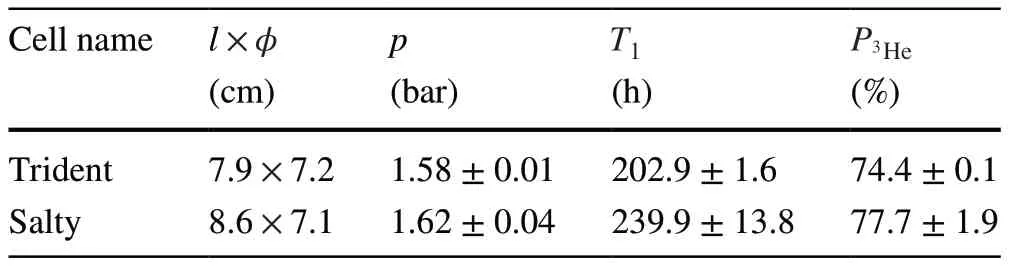
Table 1 Parameters of the customized cylindrical 3 He NSF cells,including the cell inner length l and inner diameter φ , 3 He pressure p at 25 ◦ C, maximum lifetime T1 and maximum saturated 3 He polarization P3He

Fig.3 (Color online) a Neutron polarization and transmission measured with the setup shown in Fig.2.The neutron polarization is plotted as a function of the neutron wavelength measured at different time, the transmission curves represent the high-flux spin state T++and the low-flux spin state T-+ corresponding to the measurements performed at the very beginning.b Neutron transmission data of one of the newly produced cells collected by using the ex-situ system individually.The transmission curves of the unpolarized cell and the transmission ratio of the polarized to the unpolarized cell are plotted in black and blue, respectively, where the cell pressure and 3 He polarization can be derived from the fittings based on the equations labeled in the figure [27, 28].T0 , Tn , and Te are the neutron transmittance through depolarized, fully polarized, and empty 3 He NSF cells,respectively, l is the cell inner length, n is the number density of the 3He, λ is the neutron wavelength, σ = σ0λ with σ0 being the 3 He absorption cross section for λ = 1 Å p is the cell pressure, and P3He is the 3 He polarization.The fitted values of the pressure and 3 He polarization are 2.046 bar and 52.3%, respectively
Considering the figure of merit of a neutron polarization instrument, which is widely used asQ=P2Tand is dependent on the neutron wavelength and beam angular width (α),the3He NSF has its natural advantages in the research area requiring smallerγand largerαcompared to polarizing supermirrors.This makes it more favorable for high-energy neutron scattering measurements with larger beam sizes,such as off-specular neutron reflection measurements [31,32].In general, the performance of a polarizing supermirror is considered superior at longer wavelengths, since a much higher3He polarization is required for the3He NSF to counteract the rapid decrease in neutron transmittance and achieve aQvalue comparable to that of a supermirror.Above the critical wavelength value, polarizing supermirrors have a large and constant neutron transmittance and polarization, and they perform independently of external influences.
At BL-20, to integrate the advantages of the3He NSF and supermirror, extend the available wavelength range, and improve theQof the entire beamline, we replaced the3He NSF system with a combination of a polarizing supermirror and a neutron spin flipper as the incident beam polarizer and spin flipper, respectively.The polarizing supermirror installed behind the monitor, which consists of Si wafers coated on both sides withm=4 Fe/Si thin films, wheremis a measure of critical angle in units of critical angle of nickel,was fabricated by SwissNeutronics and commissioned as a transmission geometry unit [33] (Fig.4).The supermirror was assembled in a V-shape with a taper angle of 1.19◦and mounted inside a magnetic casing with its field vertically aligned, which generated a critical wavelength of 2 Å.Behind the supermirror, an in-house developed neutron spin flipper was employed to manipulate the neutron polarization and was verified to have polarization flipping efficiency of more than 90% and over 95% neutron transmittance at wavelengths longer than 1.1 Å [34].

Fig.4 (Color online) Schematic diagram of the polarized neutron test experiment setup consisting of a supermirror, neutron spin flipper, insitu 3 He NSF system, the designed guide field system, and the neutron beam monitor and detector.The blue and black arrows represent the magnetic field and neutron evolution of the polarization along the central neutron trajectory, respectively
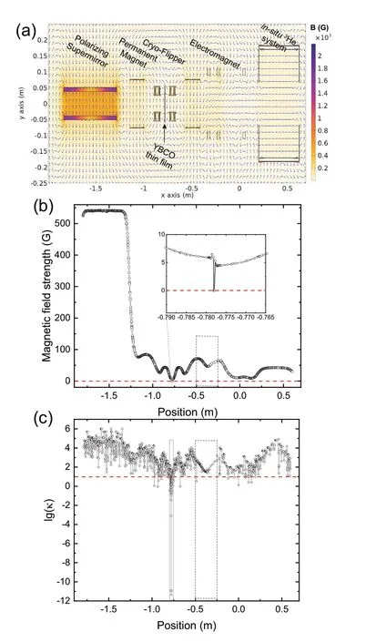
Fig.5 a Magnetic field simulation according to the beamline configuration shown in Fig.4 using the finite element method.b Onedimensional cut of the magnetic field strength distribution along the center of the neutron trajectory.c Calculated adiabaticity parameter based on the field distribution shown in b for the 2 Å neutrons.The dashed boxes in b and c represent the nonadiabatic transition area at the position of the yttrium barium copper oxide (YBCO) thin film and the adiabatic transition area between the guide field components,respectively
The main field directions between the supermirror polarizer and in-situ3He NSF analyzer were different, and a customized guide field system was required to realize the adiabatic transition of neutron polarization.Using the threedimensional finite element method of the COMSOL MultiphysicsⓇsoftware [35], we simulated the magnetic field distribution along the overall beamline using calibrated models of the polarized neutron components.This led to the design of a suitable guide-field system.As shown in Fig.5a,the field direction is initially along the vertical direction and then becomes horizontally aligned between the permanent magnet and coil components.To satisfy the condition of adiabatic transition of the neutron polarization, the field strength and positions of all components were optimized along the entire neutron path (Fig.5b).When determining the ability of the neutron spin to follow the magnetic field transitions along its trajectory, the evolution of the adiabaticity parameter (κ) is always used as a reference.This parameter is defined as the ratio of the Larmor precession frequencyωLto the changing rate of magnetic field directionωB[36],
whereγnis the neutron gyromagnetic ratio, h is Planck’s constant,θBis the angle of the magnetic field vector, and s is the distance travelled by neutrons.By applying the Bloch-Solver neutron-processing analysis software, as shown in Fig.5c, theκvalues at different positions were calculated based on the results of the magnetic field simulation.As represented byκ ≪1 (lg(κ)≪0) at the position of the neutron spin flipper, the flipping process is proven to be nonadiabatic.By contrast, for other values,κ> 10 (lg(κ) >1) at the other positions indicate the neutron polarization is preserved or manipulated adiabatically, particularly at the positions near the gap between the magnet and coil guide fields, where the neutron polarization was adjusted to be parallel to the3He polarization.The beamline setup was constructed on the basis of the aforementioned simulations.The initial and final neutron polarization states were manipulated by adjusting the working status of the flipper and flipping the3He polarization through AFP, and four neutron transmission measurements were performed.Their results are labeledT++,T--,T+-, andT-+, where the first index represents the flipper status and the second index represents the3He polarization states.Hence, the overall beamline neutron polarization can be calculated using Eq.(2).The analyzing efficiencyPn(3He) of the3He NSF system can also be determined independently from the neutron transmittancesT0andTn, which can be given by [27, 28]

Fig.6 (Color online) Neutron polarization plotted as a function of the neutron wavelength.The black curve represents the neutron polarization of the overall beamline setup shown in Fig.4.The blue curve represents the analyzing efficiency of the 3 He analyzer, obtained from the neutron transmission measurements with an in-situ system.The red curve shows the polarizing efficiency of the supermirror polarizer determined from the neutron polarization of the beamline setup and the in-situ system
Additionally, a neutron polarization analysis method was applied to demonstrate that the flipping and polarizing efficiencies of the flipper and supermirror could be differentiated and derived from the above measurements.As indicated by the black curve in Fig.6, the setup shown in Fig.4 with the neutron spin flipper turned on and the3He polarization flipped (T++andT+-) is capable of providing effective neutron polarization.Furthermore, no obvious neutron polarization loss induced by the flipper or3He AFP was observed in further measurements.The combination of the neutron polarization instruments listed above enabled a neutron polarization of more than 90% over 3 Å to be achieved, and the polarization at shorter wavelengths was improved to 50% at approximately 2 Å when the in-situ3He NSF system was applied as an analyzer instead of the supermirror.The analysis efficiency of the in-situ3He NSF system was calculated using equation (4) and is shown as the blue curve plotted in Fig.6.Accordingly, the neutron polarization is 90% at 2.2 Å and reaches 99% at 4.1 Å.The red curve shows the derived polarizing efficiency of the supermirror used on BL-20, above its critical wavelength of 2 Å and the efficiency rapidly increases to reach more than 90% at 2.4 Å.Comparing the neutron polarization performances collected by different beamline setups, the performance of the3He NSF polarizer surpasses that of the polarizing supermirror polarizer at wavelengths below approximately 2.3 Å,whereas the performance of the supermirror is more stable and consistent at longer wavelengths, which is in accordance with the characteristics of these components.
4 Conclusion
A new development platform for testing polarized neutron techniques with pulsed neutrons was verified at the neutron technology development beamline BL-20 at CSNS.Different combinations of polarized neutron instruments were used to assess the neutron beam polarization performance,including the utilization of3He NSF systems as neutron spin polarizer and analyzer, as well as the replacement of the3He NSF with a polarizing supermirror and neutron spin flipper to manipulate incident neutron polarization.Based on the design of the guide-field system supported by the simulation of the magnetic field, the neutron polarization of the former polarized neutron beam setup reached over 90% at 3.1 Å and was maximized at 94.5%, remaining stable within a difference of 1% over 14.5 h.The latter achieved neutron polarization of 50% at 2 Å, more than 90% over 3 Å, and maximum polarization of 96.5 %.
As evidenced by the diversity of the polarized-neutron setup at BL-20, the polarized neutron technique developed at CSNS is capable of supporting experiments with varied requirements in a wide range of research fields, and its feasibility makes it suitable for application to neutron beamlines at CSNS.Future developments aim to focus on improving the performance of the polarized neutron setup at BL-20 and the upcoming new testing beamline BL-8A, as well as the application to spectrometers that are currently under construction at CSNS that have corresponding requirements,such as the very small-angle neutron scattering spectrometer and the direct-geometry polarized inelastic spectrometer.
Author ContributionsAll authors contributed to the study conception and design.Material preparation, data collection and analysis were performed by Long Tian, Ahmed Salman, Chu-Yi Huang, Yu-Chen Dong,and Tian-Hao Wang.The first draft of the manuscript was written by Long Tian and all authors commented on previous versions of the manuscript.All authors read and approved the final manuscript.
Data availabilityThe data that support the findings of this study are openly available in Science Data Bank at https:// doi.org/ 10.57760/ scien cedb.10330 and https:// doi.org/ 10.57760/ scien cedb.10330.
Declarations
Conflict of interestThe authors declare that they have no competing interests.
杂志排行

Nuclear Science and Techniques的其它文章
- Applying the Kalman filter particle method to strange and open charm hadron reconstruction in the STAR experiment
- Lambda polarization at the Electron‑ion collider in China
- Measurements of absolute electron capture cross sections in He2+–He and Ne8+–O2, N2, CH4 collisions
- CFD analysis of a CiADS fuel assembly during the steam generator tube rupture accident based on the LBEsteamEulerFoam
- Production of neutron‑rich actinide isotopes in isobaric collisions via multinucleon transfer reactions
- Physics-constrained neural network for solving discontinuous interface K-eigenvalue problem with application to reactor physics