SAPT: a synchrotron‑based proton therapy facility in Shanghai
2023-12-05ManZhouZhangDeMingLiLiRenShenHaiRongZhangZhiLingChenHanWenDuMingGuRuiLiDeKangLiuYueHuPuJunFengYuJianFengChenChuChenChunLongGuoHaoGuoGeYangJiangZhiQiangJiangLinJinWenJingLiXiuFangLiYeLinMingLiuYong
Man‑Zhou Zhang · De‑Ming Li · Li‑Ren Shen · Hai‑Rong Zhang, · Zhi‑Ling Chen · Han‑Wen Du ·Ming Gu · Rui Li · De‑Kang Liu · Yue‑Hu Pu · Jun‑Feng Yu · Jian‑Feng Chen · Chu Chen ·Chun‑Long Guo · Hao Guo · Ge‑Yang Jiang · Zhi‑Qiang Jiang · Lin Jin · Wen‑Jing Li · Xiu‑Fang Li ·Ye Lin · Ming Liu · Yong‑Hao Liu · Ya‑Juan Liu · Ming Lv · Qing‑Ru Mi · Lian‑Hua Ouyang ·Wei‑Guo Shi · Hang Shu · Qi‑Sheng Tang · Kun Wang · Zhi‑Shan Wang · Jun Wu · Xiao‑Bing Wu ·Jia‑Qiang Xu · Wen‑Zhen Xu · Chong‑Xian Yin · Cheng Yu · Ren‑Xian Yuan · Qi‑Bing Yuan ·Hai‑Qun Zhang · Miao Zhang · Wen‑Zhi Zhang · Li‑Ying Zhao · Wei‑Min Zhou · Shou‑Xian Fang ·Xi‑Dong Sun · Zhen‑Tang Zhao
Abstract Because of its excellent dose distribution, proton therapy is becoming increasingly popular in the medical application of cancer treatment.A synchrotron-based proton therapy facility was designed and constructed in Shanghai.The synchrotron,beam delivery system, and other technical systems were commissioned and reached their expected performances.After a clinical trial of 47 patients was finished, the proton therapy facility obtained a registration certificate from the National Medical Products Administration.The characteristics of the accelerator and treatment systems are described in this article.
Keywords Proton therapy · Synchrotron · Slow extraction · Gantry · Beam delivery system
1 Introduction
At the well-known characteristic Bragg peak [1], protons and heavy ions lose most of their energy at the end of their traveling range in matter [2].Because of the Bragg peak, the entrance that protons and heavy ions pass receives a very low dose.For therapy, the most important feature is that there is almost no dose after the Bragg peak of proton, so the important organs can be free of irradiation there.But,there are still several doses after the Bragg peak of heavy ions.Owing to these features, proton therapy can reduce the side effects of radiotherapy, or doctors can also use it to increase organ-at-risk constraints based on the concept of the dose–volume relationship to make improved high-dose target coverage possible.Since the first dedicated proton therapy was built in 1990s [3], the requirement and application of proton therapy have grown rapidly, especially in the past decade.The number of proton therapy centers in operation and under construction increased to 103 and 37 centers in the world, respectively, by 2022, and more than 280,000 cases have been treated with proton therapy [4].The typical energy range of a proton therapy is 70–235 MeV, corresponding to a 4–34 cm distance in water.Range shifters are used for the tumors whose depth is less than 4 cm.Recently,proton computed tomography (CT) is being developed, and more than 330 MeV of beam energy is required.Two main accelerator types are used for proton therapy: cyclotrons and synchrotrons.The extraction beam current of the former is continuous and high, thus providing a high dose rate.However, the beam energy is fixed, and a degrader and energy selection system are used to obtain the required beam energy.Thus, the beam passes through the block materials generates much more radiation and radioactivation.The synchrotron is just the opposite.It can directly provide the required beam energy but with a pulsed beam current.Because the maximum energy of a synchrotron can be very high, the carbon therapies in use are all based on synchrotrons.
As shown in Fig.1, Shanghai Advance Proton Therapy(SAPT) [5] is a synchrotron-based proton therapy facility located at the Shanghai Ruijin hospital proton therapy center.The construction of the facility can be divided into two phases.Four beam lines are built in three treatment rooms in the first phase: an ocular beamline, an experimental beamline, a fixed beam line, and a 180° rotating gantry beam line.In the second phase, a 360° rotating gantry room and a new injector are developed.The SAPT phase I project was founded in 2012.The installation of accelerator equipment began at the end of 2016 and took four months.Then,the beam commissioning started at the end of April 2017[6].The equipment installation of the fixed beam treatment system and that of the 180° rotating gantry beam treatment system were finished in October 2017 and July 2018, respectively.After three years of commissioning, optimization, and third-party inspection, the first registration unit, consisting of accelerator systems and the fixed beam and 180° rotating gantry beam treatment systems, passed the acceptance test of Shanghai Ruijin hospital.Then, a clinical trial of 47 patients was performed from November 2021 to June 2022.Finally, the facility obtained its registration certificate from the National Medical Products Administration (NMPA) in September 2022.In this article, the design, construction, and commissioning results of the facility are described.Table 1 shows several general specifications of this facility.
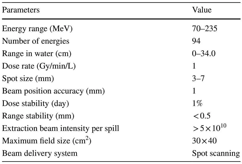
Table 1 SAPT general specifications
2 Accelerator
The SAPT accelerator system includes a 7-MeV proton LINAC, a synchrotron, two different gantries, a low-energy transport beamline (LTB) and a high-energy transport beamline (HTB).
2.1 LINAC
The LINAC (AccSys, USA) consists of a dual ion source,a 3.5-MeV radio frequency quadrupole LINAC (RFQ), and a drift tube LINAC (DTL).The LINAC is compact, with a length of less than 5.5 m.There is only an einzel lens between the ion source and RFQ.The RFQ is mounted directly on the DTL.The maximum beam current of the LINAC is larger than 10 mA.
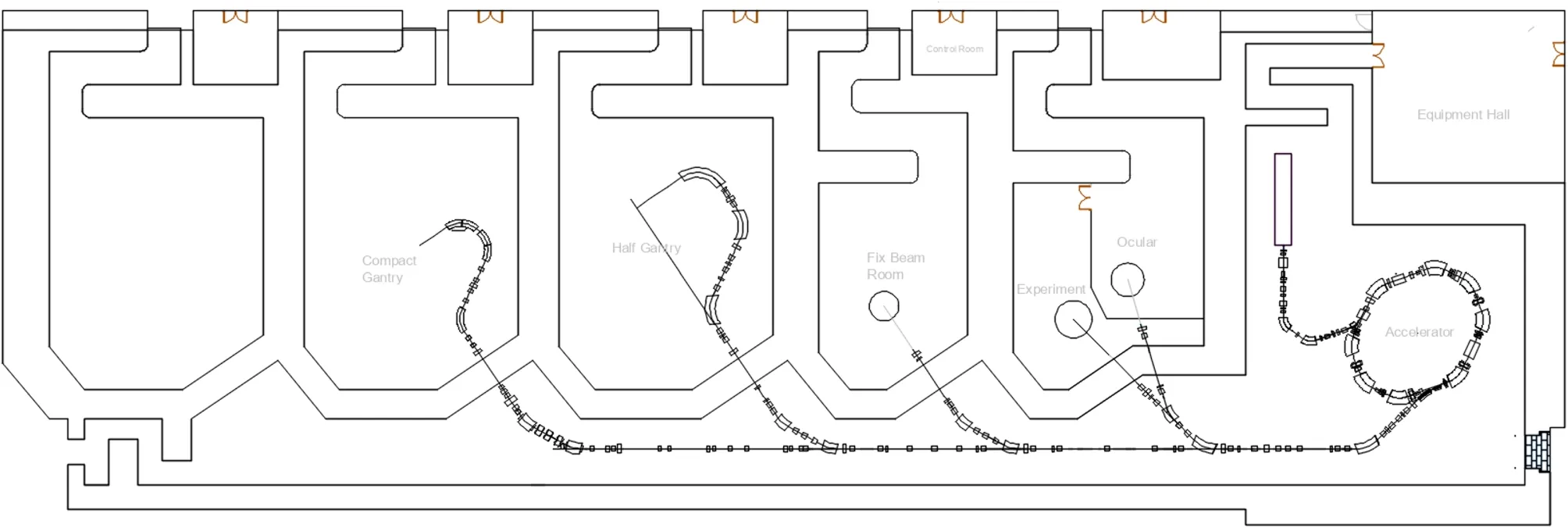
Fig.1 Layout of SAPT
2.2 Synchrotron
The synchrotron is the core part of the accelerator system.Its output energy ranges from 70 to 235 MeV with the maximum accelerated protons exceeding 1011.
2.2.1 Magnetic lattice
The SAPT synchrotron accelerates the proton beam from 7 MeV to the required energy in several million turns.Its circumference is 24.6 m, and the designed maximum extracted beam energy is 250 MeV, but the maximum extracted beam energy of daily operation is 235 MeV.The synchrotron must achieve a high stored beam intensity to increase the final dose rate at the target.The space charge effect [7] limits the maximum stored beam intensity, because of tune shift and beam loss.The tune shift is inversely proportional to the beam emittance.In a hadron synchrotron, the beam emittance is determined by injection and acceptance.Larger acceptance means a larger magnet gap or smaller beta function.Therefore, to suppress the beta function, the lattice structure of the SAPT synchrotron is carefully selected from dozens of different candidates.There are eight dipoles and 12 quadrupoles in this designed synchrotron [8], as shown in Fig.2.In this configuration, multiple quadrupoles and their short focal lengths make the beta function less than 5 m in the dipoles, which means that this synchrotron has a good acceptance.Figure 3 shows the Twiss parameters.In commissioning, the maximum accelerated particle number per spill reached 1.3 × 10¹¹at 70 MeV.Four long and four short sections are used for accommodating injection and extraction, the radio frequency (RF) cavity, the beam diagnostics,and vacuum elements.

Fig.2 Magnetic lattice structure of the SAPT synchrotron (QF:focusing quadrupole, QD: defocusing quadrupole, FQD: fast defocusing quadrupole, SD: defocusing sextupole, RFK: radio frequency kicker, BEND: dipole magnet, BUMP: bump magnet, BPM: beam position monitor, PROF: profile monitor, NPCT: current transformer,IES: injection electrostatic septum, IMS: injection magnetic septum,EES: extraction electrostatic septum, EMS: extraction magnetic septum)
The main parameters of the SAPT synchrotron are listed in Table 2.The tune is selected to be close to 2/3 resonance for the slow extraction scheme.To reduce the beam loss at the electrostatic extraction septum, the Hardt condition that aligns the separatrices of different momentums[9] is satisfied on the lattice.The protons remain below the transition energy during the whole ramping process,and to avoid head–tail instability, the chromaticity should be negative.This means the horizontal dispersion and its derivative should have different signs.Two sextupoles are used to correct the chromaticity.The phase advances of these two sextupoles are nearly 360°; thus, they affect the resonance-driven term very little if their strengths are the same.Two sextupoles with different signs are used to drive the resonance and do not cause a chromaticity change.

Fig.3 (Color online) Twiss parameters

Table 2 Main parameters of the SAPT synchrotron
2.2.2 Injection
Because the beam current from the LINAC is only approximately 10 mA, a multiturn injection scheme is employed for the accumulating beam to reach the required beam intensity [10].The injection system includes a magnetic septum, an electrostatic septum, and two bumps.The first two elements bend the injection beam into the synchrotron ring.The bumps cause the stored beam orbit close to the injection beam to achieve acceptance.The other advantage of multiturn injection is that one can enlarge the beam emittance by filling the acceptance of the synchrotron,which is called “painting”.Because of the betatron oscillation, horizontal phase space painting is performed if the relative injection position changes when the orbit bump is decreased.However, as the bump height decreases, the injection beam hits the electrostatic septum after several turns and is lost.Because of this process, the efficiency of multiturn injection is not high.Figure 4 shows the relationship between the effective turns (the ratio of the accumulated particle number and the particle number from the LINAC in one turn) and the turn number of the injection process and bump height.Increasing the injection turns decreases the efficiency, but the effective turn increases.To balance the efficiency and accumulated particle number, 30 turns were selected.Vertical phase space painting is realized using the Twiss parameters and orbit mismatch.The final injection efficiency is approximately 35%, and the maximum particle number after injection is more than 2 × 10¹¹during commissioning.

Fig.4 (Color online) Relationship of effective turns, bump height,and injection turns
2.2.3 Acceleration
The beam in a synchrotron is accelerated by the electric field established by the RF system.The SAPT RF system includes a nanocrystalline-FINEMET-core-based broadband RF cavity and a low-level RF control system.The cavity and RF transmitter work at un-resonance mode, and the control can be simplified significantly.Because the working frequency of the LINAC is significantly higher than the synchrotron revolution frequency, the proton beam after injection is nearly coasting; therefore, the beam should be bunched before acceleration.An adiabatic capture procedure, employing a special RF voltage curve, is used to increase the bunched particle number.
Once the beam is bunched, the magnet current, RF frequency and voltage are synchronously increased to “ramp”the beam to high energy [11–13].The mismatch of these parameters causes beam loss and reduces the ramping effi-ciency (the beam number accelerated to the desired energy via the beam number at the defined time).The rapidly changing magnetic field generates an eddy current in both the vacuum chamber [14] and the magnet [15].The eddy current in the dipole results in a significant magnetic field delay.According to the measurement results, the dipole current is changed to compensate for this field error.The timing delays and shape of the magnet power supply and RF curves are also carefully tuned to increase the maximum particle number after ramping.Second- and third-harmonic RF voltages are used to flatten the RF bucket and reduce the maximum bunched beam intensity [16].The space charge effect is suppressed, and the ramped proton number is approximately twice larger.Figure 5 shows the particle number in the ramping process.The main beam loss occurs in several milliseconds just after capture because of the space charge effect.The ramping efficiency is more than 80% after 0.1 s.Another beam loss occurs at 0.4 s when the second- and third-harmonic RF voltages are turned off.The accelerated particle number is only approximately 6 × 10¹⁰without second- and third-harmonic RF voltages.

Fig.5 Particle number during ramping
2.2.4 Extraction
Usually, the beam delivery system controls the dose by counting the number of electrons produced by protons in the ion chamber.Then, to increase the control accuracy, the extraction proton beam current should be kept constant, controllable, and able to be turned offquickly enough.Thirdorder resonance slow extraction makes such beams possible for a synchrotron.During the third-order resonance slow extraction scheme, the QF and QD current is first changed to move the tuning closer to the resonance line.Then, the resonance sextupoles are turned on to drive the resonance term to create an unstable region.The protons that have a large oscillation amplitude enter the unstable region.After several turns, as shown in Fig.6, they enter the electrostatic septum,are deflected by the electric field, and then pass through quadrupoles, dipoles, and the magnetic septum.Finally, they are extracted to the high-energy transport beamline.
The third-order extraction is a nonlinear progression,which is influenced by several factors, including the tune,sextupole strength, beam orbit, angle and strength of the extraction electric septum, and RF voltage.The beam separatrix step and angle at the entrance of the electrostatic septum differ when the tune and sextupole strength change.The beam orbit leads to beam center position and motion direction error at the entrance of the electric septum.All these parameters affect the extraction efficiency.The beambased alignment method in which the sextupole is turned on and offis used to measure the closed orbit.If the beam does not pass through the center of a sextupole, it detects a quadrupole field and changes the tune.The beam offset from the center is calculated and corrected by the correctors.The extraction efficiency is optimized to approximately 75% in the commissioning.Figure 7 shows the sextupole scanning result.
The extraction beam current is decided by the rate at which particles enter the unstable region.The radio frequency kicker (RFK) is used to enlarge the beam emittance[5, 17].The frequency of the RFK is near the betatron tune.The enlarging rate of the proton beam emittance and, thus,the extraction beam current is controlled by the amplitude modulation of the RFK voltage, as described elsewhere [17].The amplitude during the extraction is changed to make the extraction beam current constant.Figure 8 shows the measured extraction beam current at the HTB.The dose accuracy requires the extracted beam to be turned offrapidly [18].The cutofftime has been studied well, and the result is shown in Fig.9.After the beam delivery system sends a turnoffsignal, the beam is cut offto approximately zero in less than 0.32 ms.

Fig.7 (Color online) Sextupole optimization

Fig.6 Simulated extraction orbit

Fig.8 (Color online) Measured extraction beam current at HTB

Fig.9 (Color online) Cutofftime after received signal
2.3 Transport line
The transport line mainly includes the LTB and the HTB.The transport line on the gantry is described in the next section.
(1) LTB
The LTB transports proton beams from the LINAC to the injection systems of the synchrotron.There are several beam diagnostic elements in the LTB to measure the beam parameters of the LINAC.A debuncher, which is used to reduce the momentum spread and increase the injection efficiency,is installed in the LTB.
(2) HTB
The HTB transports extraction beams from the synchrotron to the required treatment room.The HTB can be divided into a match sector and several extensible repetition sectors according to the different functions.The beam optics at the exit of the match sector are dispersion-free and beam waist.The extensible sectors include the beamline in each treatment room and some parts in the accelerator tunnel.The vertical and horizontal beam sizes are determined by the beta function and phase advance, respectively.
2.4 Gantry
A medical physicist often requires more beam direction to reduce the dose at the organ at risk.A rotating gantry is a large mechanical device that rotates the beam transport line and treatment nozzle to different beam irradiation angles.The size and shape of the gantry are determined by the beam transport line.Two different gantries, namely a 180° rotating gantry and a 360° rotating compact gantry, were designed based on the round beam method [19].The beam transfer matrix from the entrance to the exit of the 180° rotating gantry beamline is an identity matrix,so the beam profile at the exit of this gantry is the same as the one at the entrance.The beam optics do not need to change while the gantry rotates.Figure 10a shows the measured beam size when the gantry is at 270°, kept within a 15% tolerance.Tumors at almost all body positions can be treated easily with the 180° rotating beamline in cooperation with the rotation of the couch.The advantage is the large open space for patients and technicians.However, this characteristic causes many mechanical difficulties because of the unbalanced structure, such as the support and deformation control of the gantry.The installation position of the orthogonal X-ray system is also difficult to choose.The rotated part weighs 96 tons, and the total gantry weight is less than 170 tons [20].When the gantry rotates, the measured mechanical and beam position errors at the isocenter are within 1 mm.Figure 10b shows the distance from the measured beam position to the isocenter at different angles and energies when the beam is irradiated to the nominal zero point.Currently, there are six gantry angles: 0°, 330°, 315°, 270°, 225°, and 180°.The different colors stand for 94 energies.The distances are all less than 1 mm.

Fig.10 (Color online) (a) Beam sizes at 270° and (b) beam position errors at different angles and different energies
The distance from the end of the last dipole to the isocenter decides the gantry size.The distance is shortened to reduce the gantry size.If the scanning magnets are placed after the dipole, the radius of the gantry is large.If the scanning magnets are placed before the dipole, the radius is small, but the gap and weight of the last dipole are large.A combined function dipole magnet can also be introduced to compress the beta function.This reduces the total weight of the magnets from 23 to 13 tons.Figure 11 shows a side view of the 360° rotating gantry, and the total weight and rotation weight of this compact gantry are 130 and 93 tons, respectively.The measured mechanical errors of the 360° rotating gantry at the isocenter are within 0.2 mm, which is considerably smaller than that of the 180° rotating gantry.
3 Treatment rooms and treatment system
There are four treatment rooms in SAPT, each requiring corresponding treatment systems.The treatment systems include a beam delivery system, positioning system, treatment control system (TCS), image-guided radiotherapy(IGRT), treatment plan system (TPS), oncology information system (OIS), and quality assurance (QA).
The positioning system includes a robot couch and several laser lamps.The couch supports the patient or QA equipment.The movement and rotation accuracy of the couch are less than 1 mm and 0.2°, respectively.The laser lamps indicate the position that must be moved to.The OIS receives treatment plans and CT information from the TPS and then sends them to the IGRT and TCS, respectively.Finally, the OIS receives and confirms the results after positioning or treatment.The TCS controls the irradiation workflow, treatment room switch, and interlocks.The TPS generates irradiation plans, such as spot positions, spot doses, and energy layers, according to the target delineation results and beam model.The beam delivery system, OIS, TPS, and TCS of the fixed room, 180° gantry room, and 360° gantry room are almost identical.The control system and structure of the couches are slightly different.
3.1 Beam delivery system
The beam delivery system controls the proton beam irradiation process according to the treatment plan.Owing to its excellent 3D conformability, the scanning method is widelyused in hadron therapies.Several different scanning methods exist, including spot scanning, raster scanning, and line scanning.In the SAPT facility, the beam delivery system of eye treatment room uses double scattering method.The nozzle has a range modulator, first scatterer, second scatterer,aperture, collimator, and three dose monitors.The scatterers spread the beam transverse profile and create a flat dose distribution.The range modulator is a rotating wheel with different depths.When the proton beams pass different positions of the wheel, they lost different energy and then provide the required depth dose distribution.

Fig.11 (Color online) Side view of the 360° gantry
The fixed beamline and rotating beamlines employ spot scanning [21].There are two scanning magnets, two dose monitors, one position monitor, and their control cabinet in the SAPT irradiation system [22].The scanning magnets kick the proton beam to the target position, while the magnetic field is measured and controlled [23].The beamposition is monitored by the position ion chamber.The control system measures and controls the dose according to the main dose ion chamber, and the secondary dose ion chamber provides the dose signal for verification [24].Any one of these three measurement quantities (main dose, secondary dose, and beam position) exceeding the threshold can trigger an interlock to stop the irradiation.Depth direction modulation is realized by the energy change through the accelerator control system.However, there is no beam available for irradiation during the ramping process, which makes the synchrotron less efficient.

Table 3 Dose performances
The beam delivery system represents the performance of a proton therapy facility.Almost all the important parameters are measured from the system [25].The standard IEC 62667 prescribes the measurement method for these parameters.The measured dose performances at the isocenter are listed in Table 3.Figure 12 gives the dose errors of different energies and different doses per spot.The maximum dose per spot is 0.15 monitor units (MU), and the minimum dose per spot is 0.006 MU.The absolute dose errors of a single spot are almost the same at large and small doses per spot,so the relative dose error is large at a small dose.
3.2 Treatment rooms
1) Eye treatment room
This room focuses on ocular tumors and maculopathy.The treatment systems are different from those in other treatment rooms.There is a double scattering nozzle, treatmentchair, orthogonal x-ray system, nozzle control system, and treatment control system.Because of the double scattering and the tumor being shallow, the beam energy is 75 MeV.The different beam delivery method leads to a different data type being transferred from the TPS to the OIS and TCS.

Fig.12 Dose errors of different energies and different doses per spot
2) Fixed treatment room
The beam direction in this room cannot be changed and focuses mainly on head, neck, and pelvic tumors.Multifield treatment can be provided in conjunction with the rotation of the couch.
3) 180° gantry treatment room
Because of the rotation of the gantry, a much greater irradiation angle can be used to treat the tumors, such as thoracic, abdominal, and spinal tumors.The couch can be turned to match the angle of the rotating gantry.The 180°gantry room has a respiratory gating system to monitor patient movement.This system sends beam on and offsignal to control the irradiation according to the movement threshold.
4) 360° gantry treatment room
A cone beam computer tomography (CBCT) system is installed in the compact gantry room.CBCT can achieve a more accurate positioning result.Because of the full rotation, the angle of the couch does not need to change much.It is more convenient and efficient, but there is less space for the patient and technicians.A CT-on-rail will be installed in this room.
4 End‑to‑end test and third‑party inspection
The treatment systems were carefully integrated.Many end-to-end tests and real clinical plans were used to check the functioning and performance of the facility.
The real treatment plan is more complicated than that in the IEC62667 cases.Dose calculation [26], the beam model [27], and different techniques [28] are carefully considered by the clinical team of Shanghai Ruijin Hospital.Figure 13 shows a typical measurement result.The gamma pass rate is a parameter that shows the overall performance.The dose distribution is measured by a 2D array ion chamber [29] and compared with the planned dose at different depths.The space between the two ion chambers is 7.5 mm.A gamma pass rate of higher than 95% at a ± 3%/ ± 3-mm level is a common requirement.The left top figure shows the measured dose distribution at a given depth, and the left bottom figure shows the designed dose distribution.The top right figure shows the statistics of the measured dose, where each pixel stands for an ion chamber.The bottom right figure shows the dose error between the measured and designed doses.

Fig.13 (Color online) Gamma pass rate of a treatment plan
The IEC 60601–2-64 standard [30] provides the safety requirements, including interlock and additional dose.All the performances and safety approaches of the fixed beam line and the 180° rotating beam line passed the third-party inspection and acceptance testing of the hospital.Serving as a clinical equipment, the electrical safety, electromagnetic compatibility [31], and TPS [32] also had to pass third-party testing and examination.
According to the regulatory requirements, a clinical trial of 47 patients was conducted after the acceptance testing.The target tumors were distributed in the chest, abdomen,pelvic area, spine, and head and neck.The patient ages ranged from 32 to 80 years.The irradiating fractions ranged from 5 to 38.After three months of follow-up, the local control rate of the tumor was 100%, and there were no grade 3 or higher adverse reactions.
During the clinical trial, the SAPT facility worked well.The total beam time of the clinical trial was nearly 2000 h,the beam interlock number during the trial was 147, and most of the interlock only needed a reset.The longest fault time was 90 min, with nine faults of more than 20 min.The facility availability was more than 98.5%.
5 Conclusion
A synchrotron-based proton therapy facility was successfully developed in Shanghai.Owing to the hard work of the project team, Ruijin hospital team, and third-party medical device testing team, this facility was carefully commissioned and reliably operated during its clinical trial.The beam parameters of the fixed beam and rotating beam treatment systems reached their specifications.The third-party testing,acceptance testing, and clinical trial were completed.The first registration unit obtained its medical device registration certificate issued by the NMPA and was opened for patient treatment in July 2023.
AcknowledgementsThe facility described in this article is an outcome of joint research of the Shanghai Institute of Applied Physics, Shanghai Advance Research Institute, and Shanghai APTRON Particle Equipment Co., Ltd.The work is supported by the major projects for strategic emerging industry of the Shanghai local government and National Key R&D Program of China.The close cooperation with Shanghai Ruijin Hospital and Beijing Inspection Institute makes the work more effective and efficient.We would like to thank all the people who support and help us with the design, construction, and commissioning of the facility.Their invaluable advice and help are very much appreciated.We would also like to thank all our team members–the author list is not long enough to show their names.Their hard work has enabled this project to be realized.The authors would like to take this opportunity to thank everyone involved for their guidance and support in the research and development of this proton therapy facility.
Author contributionsAll authors contributed to the study conception and design.Material preparation, data collection, and analysis were performed by De-Ming Li, Li-Ren Shen, Hai-Rong Zhang, Zhi-Ling Chen, Han-Wen Du, Ming Gu, Rui Li , De-Kang Liu, Yue-Hu Pu,Jun-Feng Yu, Jian-Feng Chen, Chu Chen, Chun-Long Guo, Hao Guo,Ge-Yang Jiang, Zhi-Qiang Jiang, Lin Jin, Wen-Jing Li, Xiu-Fang Li,Ye Lin, Ming Liu, Yong-Hao Liu, Ya-Juan Liu, Ming Lv, Qing-Ru Mi, Lian-Hua Ouyang, Wei-Guo Shi, Hang Shu, Qi-Sheng Tang, Kun Wang, Zhi-Shan Wang, Jun Wu, Xiao-Bing Wu, Jia-Qiang Xu, Wen-Zhen Xu, Chong-Xian Yin, Cheng Yu, Ren-Xian Yuan, Qi-Bing Yuan,Hai-Qun Zhang, Miao Zhang, Wen-Zhi Zhang, Li-Ying Zhao, Wei-Min Zhou, Shou-Xian Fang, Xi-Dong Sun and Zhen-Tang Zhao.The first draft of the manuscript was written by Man-Zhou Zhang, and all authors commented on previous versions of the manuscript.All authors read and approved the final manuscript.
Data availabilityThe data that support the findings of this study are openly available in Science Data Bank at https:// doi.org/ 10.57760/ scien cedb.j00186.00196 and https:// cstr.cn/ 31253.11.scien cedb.j00186.00196.
Declarations
Conflict of interestMan-Zhou Zhang and Zhen-Tang Zhao are editorial board members for Nuclear Science and Techniques and were not involved in the editorial review, or the decision to publish this article.All authors declare that there are no competing interests.
Open AccessThis article is licensed under a Creative Commons Attribution 4.0 International License, which permits use, sharing, adaptation, distribution and reproduction in any medium or format, as long as you give appropriate credit to the original author(s) and the source,provide a link to the Creative Commons licence, and indicate if changes were made.The images or other third party material in this article are included in the article’s Creative Commons licence, unless indicated otherwise in a credit line to the material.If material is not included in the article’s Creative Commons licence and your intended use is not permitted by statutory regulation or exceeds the permitted use, you will need to obtain permission directly from the copyright holder.To view a copy of this licence, visit http://creativecommons.org/licenses/by/4.0/.
杂志排行

Nuclear Science and Techniques的其它文章
- Applying the Kalman filter particle method to strange and open charm hadron reconstruction in the STAR experiment
- Lambda polarization at the Electron‑ion collider in China
- Measurements of absolute electron capture cross sections in He2+–He and Ne8+–O2, N2, CH4 collisions
- CFD analysis of a CiADS fuel assembly during the steam generator tube rupture accident based on the LBEsteamEulerFoam
- Production of neutron‑rich actinide isotopes in isobaric collisions via multinucleon transfer reactions
- Physics-constrained neural network for solving discontinuous interface K-eigenvalue problem with application to reactor physics