Endurance-test and theoretical prediction of a rare earth nanocathode for the applied field magnetoplasmadynamic thruster
2023-11-16GeWANG王戈YongLI李永ChengZHOU周成YanmingWEI魏延明ChuncaiKONG孔春才XuechengZHENG郑学程XinweiZHANG张心霨ZhimaoYANG杨志懋JinxingZHENG郑金星YuntianCONG丛云天andBaojunWANG王宝军
GeWANG(王戈), YongLI(李永),∗,ChengZHOU(周成),YanmingWEI (魏延明),Chuncai KONG(孔春才),XuechengZHENG (郑学程), Xinwei ZHANG (张心霨),Zhimao YANG(杨志懋),JinxingZHENG (郑金星),Yuntian CONG(丛云天)andBaojunWANG (王宝军)
1 Beijing Institute of Control Engineering, Beijing 100080, People’s Republic of China
2 Ministry of Education Key Laboratory for Non-equilibrium Synthesis and Modulation of Condensed Matter, Shaanxi Province Key Laboratory of Advanced Functional Materials and Mesoscopic Physics,School of Physics, Xi’an Jiaotong University, Xi’an 710049, People’s Republic of China
3 Institute of Plasma Physics, Hefei Institute of Physical Sciences, Chinese Academy of Sciences, Hefei 230031, People’s Republic of China
Abstract
Keywords: magnetoplasma dynamic thruster, nano-oxide cathode, ablation models
1.Introduction
The magnetoplasmadynamic thruster (MPDT) ionizes the propellant through a high-temperature arc generated with a high current, and accelerates the plasma with the Lorentz forces of magnetic fields and currents to produce thrust[1,2].Theoretically, magnetic plasma propulsion technology can achieve large power (up to megawatt), large thrust (up to ten Newton and high specific impulse(up to more than 10 000 s),which is likely to be the most suitable main propulsion system for space vehicles.It has significant advantages in orbit rising,deep space exploration and interstellar flight of space vehicles [1, 3].
In 1965,Ducati et al[4]conducted an experimental study on the lifetime and specific impulse of the self-field magentoplasmadynamic thruster (SF-MPDT), and the results showed that the lifetime of the cathode and specific impulse were mutually restricted.In the late 1980s, Esker et al [5]developed the X-7 applied-field magnetoplasmadynamic thruster(AF-MPDT).With a power of 32 kW,the service life of the cathode of the thruster reached 500 h.From 1994 to 1998,MAI and NASA JPL jointly developed AF-MPDT with different powers.The multi-channel hollow structure was used as the cathode structure and lithium was used as the propellant.The results show that the hollow structure can effectively reduce the cathode erosion and prolong the life of the thruster.In 2015,Nagoya University in Japan developed a rectangular AF-MPDT in order to study the phenomenon of cathode erosion.The hollow cathode was made of commercial tantalum, and the anode and cathode are positioned on opposite sides for the first time.No serious corrosion was observed on both cathode and anode surfaces after the thruster operation [6].This university measured the cathode surface temperature and plasma flow field in the discharge chamber in 2019, and clarified the relationship between the temperature distribution on the cathode surface of the thruster and the spatial distribution of plasma near the cathode [7].
In 2019, the Beijing Institute of Control Engineering successfully developed a 100 kW AF-MPDT thruster.The cathode material was a commercial tantalum tungsten with nine hollows,and the erosion on the cathode surface was very light after 10 h of operation [8].In 2021, this institute developed a 150 kW AF-MPDT with a superconductive coil.The integrated experiments demonstrated that better uniformity and stronger magnetic fields are obtained when combined with superconducting coils, resulting in more uniform cathode erosion,which not only extends the service life of MPDT, but also improves its performance [9].
The variation of working parameters and structure will affect the performance of MPDT.So researchers conducted a series of studies to improve its performance.Liu et al [10]investigated the potential to enhance their plume performance using a high-gradient magnetic field based on superconductor technology.Wu et al [11] proposed a new design for AFMPDT and found that the thrust could be increased by more than 15% on average by changing the chamber of a conventional AF-MPDT under high magnetic fields.
However,the cathode life remains the key factor limiting the lifetime and performance of the MPDT compared with other factors.For example, Wu et al [12] studied the erosion site of the graphite cathode to determine the effects of the applied magnetic field and the mass flow ratio of the positive electrode to the propellant.When working at 2000 K,thorium tungsten cathode has an emission current density of 2-3 A cm−2and a working life of more than 10 000 h.It is the cathode material with the best performance for thrusters[13-15].Most thrusters before 2010 used a thorium tungsten cathode.However,when the temperature exceeds 2300 K,the thorium atomic layer will be depleted rapidly [16], which shortens the life of MPDT cathode.As a natural radioactive element, thorium will cause radioactive pollution in the production, causing great harm to human health, and has poor erosion resistance.Therefore, it is necessary to find environmentally friendly and long life thorium tungsten cathode replacement materials.Non-radioactive rare Earth oxides have become the best alternative materials for thorium tungsten cathodes due to their advantages of low work function, high electron emissivity and strong erosion resistance.Under the same conditions, the loss rate of thorium tungsten cathode is more than twice that of oxide cathode,and the service life of cathode is greatly increased [17].
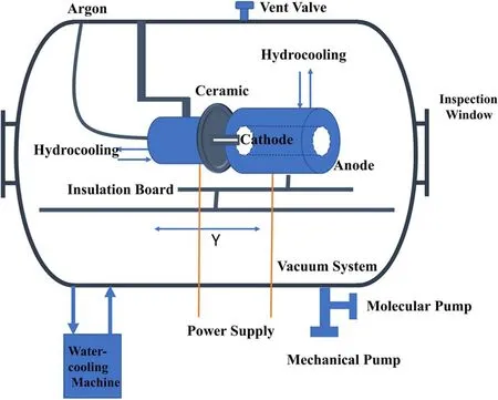
Figure 1.The diagram of cathode endurance test system.
Therefore,in this work,a nano-rare Earth oxide tungsten cathode was prepared, and the cathode corrosion problem of the cathode test plasma generator with the same magnetic field structure and gradient as the 150 kW AF-MPDT with superconducting coils was studied.The 540 h cathode endurance test was carried out,the steady state erosion model of the cathode was established, which found out the erosion mechanism and the strategy of improving service life of cathodes.
2.Design and composition of cathode life assessment system
2.1.Experimental equipment
Based on the working principle and the structure of the 150 kW level AF-MPDT with a superconductive coil developed a cathode test plasma generator,a plasma generator consisting of two opposite sides of a ring water-cooled anode and a watercooled cathode with two electromagnetic coils installed outside the anode is designed.In order to simulate the real operating environment of the cathode,the cathode endurance test system with a high temperature plasma environment is built,which is composed of a cathode test plasma generator with two electromagnetic coils, a vacuum and water cooling system, a power and gas supply system and auxiliary optical equipment.The system diagram is shown in figure 1.
2.1.1.Cathode test plasma generator.The plasma generator is the core device of the entire test system, which is fixed on the displacement platform by a steel frame, and the axial displacement is controlled by a stepper motor, which can adjust the relative position between the anode and the test cathode.The design drawing of the whole plasma generator is shown in figure 2(a).

Figure 2.(a) The diagram of the cathode test plasma generator, (b) schematic of a single-hollow WCe20 cathode, (c) diagram of the Helmholtz double solenoid coil, and (d) central magnetic field distribution.
In this experiment, nano-rare Earth oxide CeO2with a mass fraction of 2% was added to the cathode to form a tungsten-based cathode, whose structure is shown in figure 2(b), with an outer diameter of 5 mm, a pore size of 2 mm, and a total cathode weight of 4.475 × 10⁴mg.According to the type and content of oxide, the cathode is named WCe20.Figure S1 shows some characterization of the WCe20 cathode in the Supporting Information Text S1.
In order to simulate the working conditions of the 150 kW class superconducting magnetic plasma thruster more realistically, a Helmholtz double solenoid coil is installed on the plasma generator platform,and the cathode of the thruster is located in the center area of the horizontal magnetic field line by adjusting the relative distance of the double electromagnetic coil, and the magnetic field system and magnetic field line distribution are shown in figure 2.The magnetic field coil is made of red copper, and the number of turns is 468 turns.It is connected with the external precision power supply,and the magnetic field intensity is controlled by adjusting the current.According to the design, when the relative distance of the magnetic field coil is 60 mm and the current size is 2.2 A,the magnetic field intensity in the central region is 103 Gs.
2.1.2.Vacuum and water cooling system.The vacuum system consists of a vacuum chamber, a vacuum mechanical pump, a molecular pump and a vacuum gauge.The mechanical pump is a backing pump,and the molecular pump is a secondary pump.The water flow rate of the chiller used in this experiment is 58 l min−1, the cooling capacity is 17.5 kW h−1, and the circulating water temperature is set in the range of (20-24)°C.
2.1.3.Power and gas supply system.The power supply system used in this experiment operates at 50 Hz,which has a three-phase input voltage of 380 V,a no-load voltage of 80 V,a maximum output power of 15 kW,an arc starting voltage of 3 kV,a maximum output current of 120 A,a minimum output current of 10 A, and a push-type contact arcing.The experimental working fluid enters the cathode gas supply end of the vacuum chamber through the gas flow meter from the outlet of the gas cylinder,and the propellant used is highpurity argon (purity of 99.999%).The system diagram is shown in figure 3.Figure S2 shows some details of the Figure 3.The circuit diagram and the gas circuit diagram of the power and gas supply system.The DC source system supplies power to the cathode so that the high purity argon can be ionized and discharged through the gas path system into the vacuum chamber.The water cooling machine cools the cathode and anode throughout the process.cathode clamping sleeve and schematic diagram of anode design in the Supporting Information Text S2.
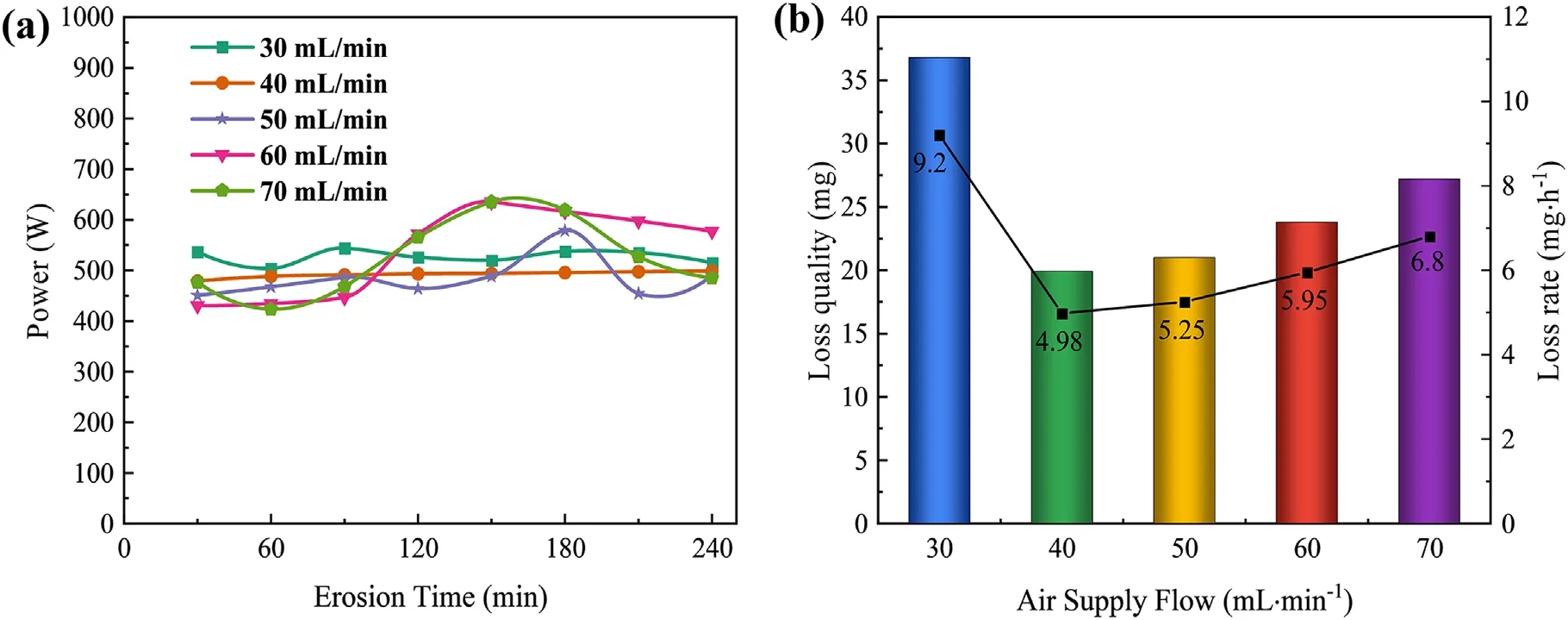
Figure 4.(a) Cathode power versus time curve, and (b) loss mass and loss rate under different gas supply flow.
2.1.4.Optical equipment.High-speed photography captures changes in the cathode during arcing, and its high-speed shutter captures details that cannot be distinguished by the naked eye.This experiment uses a Phantom V2512 highspeed camera paired with a Nikon 135 mm prime lens.Figure S3 shows some details of the spectrum acquisition system schematic diagram for the electron temperature in plasma plumes in the Supporting Information Text S3.
2.2.Analysis of influencing factors of cathodic erosion
The purpose of this work is to analyze and model the erosion mechanism of the cathode through experimental methods,and to guide the prediction of the theoretical lifetime of the cathode.Firstly,sensitivity tests are carried out on key factors to determine the optimal working conditions of the cathode as operating parameters for the long-term experiment of the cathode.The erosion time is defined as the duration of the ignition of the cathode in vacuum.
2.2.1.Propellant supply flow factor.When the discharge current is 20 A, the magnetic field strength is 96 Gs, and the continuous working time of the cathode is 4 h, the influence of different propellant supply flows on the cathodic erosion is shown in figure 4.The cathode loss mass is obtained by opening the hatch door and weighing after the cathode worked under different flow conditions for 4 h.
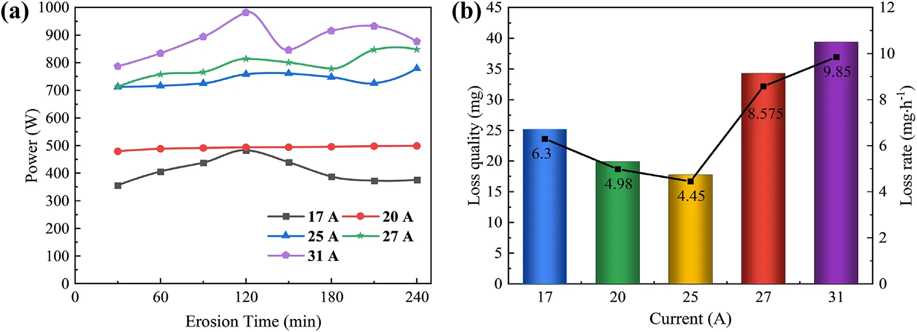
Figure 5.(a) Cathode Power versus time curve, and (b) loss mass and loss rate at different currents.
Compared to high flow, the power variation is smaller under low flow conditions,especially in the 40 ml min−1flow case, where the cathode power is reduced and the change is most stable (shown in figure 4(a)).The change of power is related to the establishment of the plasma region.When the gas flow rate and plasma density decrease and the conductivity weakens,the power supply increases the discharge voltage and power through the feedback mechanism, and then the plasma ionization degree and density are improved.However,at a low flow rate, the residence time of the high-heat plasma in the cathode is prolonged,the cathode temperature is high,and the corrosion will be more serious.The fast flow speed makes the established plasma conductive field easy to be blown away by the high speed flow,resulting in power instability.The molten layer particles on the surface of the cathode will be driven out by the high-speed flow,and the cathode loss will increase.The loss mass and loss rate of the cathode under different propellant supply flows are shown in figure 4(b).The loss rate of the cathode shows a trend of decreasing first and then increasing with the increase of the propellant supply flow.It is suggested that the loss is the most serious at 30 ml min−1, and the loss rate is the lowest at 40 ml min−1.
2.2.2.Discharge current factors.When the propellant supply is 40 ml min−1, the magnetic field strength is 96 Gs, and the continuous working time of the cathode is 4 h, the influence of different discharge currents on cathodic erosion is shown in figure 5.
The output power increases with the increase of current density,and the output power fluctuates to varying degrees with the extension of erosion time at the same current density.With the most stable change of the power at 20 A, and the power showing a trend of first decreasing and then increasing when current above 20 A (shown in figure 5(a)).When the plasma ionization efficiency is low and the conductive effect with the inner wall of the anode is small, the constant current source increases the voltage and input power through the feedback mechanism.The electron emission efficiency increases to produce more plasma,as charged particles in the plasma region approach saturation, the power required to maintain their electron emission efficiency decreases, which is a dynamic equilibrium process.The loss mass and loss rate of the cathode under different current densities are shown in figure 5(b).Corresponding to the power change, the erosion rate of the cathode firstly decreases and then increases with the increase of current.It is suggested that the erosion of the cathode is the lightest at 25 A.
2.2.3.Magnetic field strength factors.The correspondence between the input current of the magnetic field coil and the strength of the central magnetic field is 0 A(0 Gs),1 A(68 Gs),2 A(96 Gs),3 A(145 Gs).The central magnetic field strength is measured by a Gaussian meter.When the supply air flow is 40 ml min−1, the discharge current is 25 A, and the cathode is running continuously for 4 h, the influence of magnetic field strength on cathodic erosion is studied (figure 6).
The relationship between the input power of the cathode and time during the erosion process is shown in figure 6(a).The introduction of a magnetic field will increase the input power; the stronger the magnetic field, the greater the power.This is due to the plasma plume being compressed, the conductivity of the inner wall of the anode is weakened, the constant current source increases the input voltage and power through the feedback mechanism.The erosion mass and erosion rate of the cathode under different magnetic field strengths are shown in figure 6(b).The cathode loss is the largest when there is no magnetic field exist, and the loss rate of the cathode gradually decreases with the increase of the magnetic field strength.This phenomenon is due to the fact that under the action of the additional magnetic field, the plasma shrinks and moves outward to accelerate helically,reducing the degree of aggregation of high-heat plasma on the surface of the cathode, thereby reducing the cathode temperature and alleviating erosion.Moreover, the cathode electron emission mode is spot emission,and the spot constantly moves under the action of the magnetic field, avoiding local overheating and reducing erosion.When the additional magnetic field is 96 Gs,the cathodic erosion rate is reduced by about 49.3%, and the erosion rate is only 4.450 mg h−1,but the erosion rate increases slightly when the additional magnetic field is 145 Gs,which is related to the large power fluctuation.
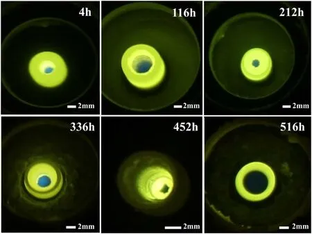
Figure 7.Photos of the cathode over time.
3.Cathode endurance test
According to the above test results, an endurance erosion experiment was carried out on the WCe20 cathode to obtain the relationship between cathodic erosion mass and time under optimal operation conditions,and a steady-state erosion model of tungsten cathode surface was established, which provided experimental data basis for evaluating the theoretical life of the cathode.
3.1.Experimental process
3.1.1.Experimental parameters.The propellant supply flow is 40 ml min−1, the discharge current is 25 A, and the central magnetic field strength is 96 Gs.
3.1.2.526 h endurance experiment.In the first 100 h, the process stops every 4 h, opens the cabin to weigh the mass loss of the cathode, 100 h to 526 h, stops every 16 h, opens the cabin to weigh the mass loss of the cathode, and records the relationship between mass loss and erosion time respectively.Figure S4 shows some details of the erosion loss mass of the WCe20 cathode changes with the running time in the Supporting Information Text S4.
3.1.3.Starting loss experiment.When the cathode erodes to 526 h, 191 times start-up erosion experiments are carried out on the cathode.From 1 to 20 times, the thruster start-up running time is 5 s, the cooling time is 5 min, and the subsequent 171 start-up erosion experiments,the thruster runs for 5 min, the cooling time is 5 min, and the start-up loss of the cathode is studied under the condition of ensuring that the cathode can be sufficiently cooled.
3.1.4.Topography measurement.SEM (scanning electron microscope) was used to observe the surface morphology of the cathode material after erosion.
3.2.Endurance test result
The change of cathode during the 526 h endurance test is shown in figure 7.The results revealed that a molten layer appears on the inner hole wall of the cathode,and the molten layer material is a low melting point and low escape work substance.The loss of the cathode is concentrated in this position, and the pore size gradually increases with the extension of the erosion time, and the length gradually decreases with consumption.At 212 h, 336 h and 452 h, the molten layer accumulation in the inner pore was caused by the migration of the molten layer on the inner surface to the front end driven by the rapidly flowing plasma.The macroscopic morphology of the cathode after erosion is shown in figure 8.The surface of the cathode is rough, there is a‘shrinkage’ in the middle, the front end has been eroded to a thin-walled state.The measured result showed that the outer diameter is 4.89 mm, the inner diameter is 4.11 mm, and no macro crack appears at the front end of the cathode.
3.3.Start-up erosion experiment results
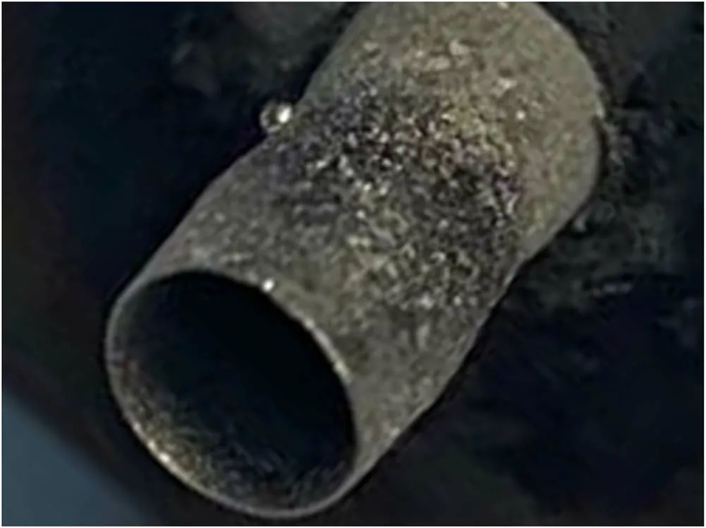
Figure 8.Cathode morphology after erosion.
Experimental studies have shown that the start-up process of the cathode can cause serious erosion.The start-up erosion has nothing to do with the power,but is related to the arc initiation mode of the power supply,the start-up time and the surface state of the cathode.When the CeO2distribution on the surface is uniform,the vacuum arc is randomly generated,and the start-up erosion is related to the effective discharge area of the cathode.In the start-stop experiment with a duration of 5 s in 1 and 20 times, the average start-up loss was 0.750 mg, the start-up loss rate was 540.0 mg h-1,and the erosion flux density was 5.580×10⁻⁴mg mm-2s-1.In the subsequent 171 times of 5 min startstop experiments, the average start-up loss was 0.790 mg, the erosion flux density was 5.870 × 10⁻⁴mg mm-2s-1, and the start-up loss rate was 568.8 mg h−1.As the number of ignitions increases, the start-up loss of the cathode increases, which may be due to the fact that each discharge is first generated at the accumulation of low melting point substances on the surface,the loss is accelerated because of high temperature.
4.Mathematical model of the steady-state erosion
According to the working mechanism of the cathode, the cathodic erosion process can be divided into two stages,start-up erosion and steady-state erosion.On the surface of the cathode,when the current density reaches a certain value, the plasma temperature is higher than the melting point of the cathode material,and the high temperature will definitely form a melting layer on its surface, and the process from the beginning of erosion to the formation of the molten layer is called start-up erosion.When the oxide migration rate is equal to the erosion consumption rate, the molten layer is stably formed, reaching a thermal equilibrium state,and the cathode is in a steady state of erosion.The following mathematical model is established for steady-state erosion.
4.1.The relationship between discharge current and current density
During the actual operation of the cathode, the discharge current is not evenly distributed on the surface of the cathode,but is limited to the surface micro-area, forming local points with high current density, which will also produce erosion spots on the surface, as shown in figure 9.Though the arc spots at the beginning are large (about 60 μm), they were small in quantity.However, in the steady state, the distribution of the spots was more uniform,resulting in small erosion spots, with a size below 20 μm.
Under short-term erosion conditions, these spots have a good correspondence with current density.The cathode was subjected to erosion experiments for 1 min under different discharge currents, and the cathode was in the steady-state erosion process,and the start-up erosion spots were deducted from the resulting erosion spots,which could be considered as the erosion spots corresponding to the current density of the steady-state process.The erosion spot area of the cathode was observed and counted using a scanning electron microscope,the average spot current density under different discharge current was calculated, as shown in table 1.
Calculating the relationship of the discharge current and current density according to the least squares method,the results is shown in figure 10.The empirical formula for fitting is:
Equation (1) is the basis for erosion modeling and lifetime prediction, through which the current density of the cathode at high currents can be inferred.
4.2.Evaporation loss calculation
Since high surface temperatures are required to maintain a stable discharge,erosion at steady state is mainly evaporative erosion.According to the Hertz-Knudsen formula(2),the flux density(evaporation rate per unit area)of an evaporated atom is [18]:
where T is the cathode temperature,p(T) is the vapor pressure of the cathode material at T temperature,M is the atomic mass of the cathode material,k is the Boltzmann constant,γ is the escape factor,and the escape factor of the metal surface in vacuum is about 82%.
As long as the temperature of the cathode and the saturated vapor pressure at the corresponding temperature are obtained, the theoretical evaporation loss of the cathode can be calculated.The local temperature of the tungsten cathode determines the saturation vapor pressure in this local area;thus, determines the erosion rate in this region.Taking the gasification point TBat atmospheric pressure as the reference point, according to the Clausius-Clapperon equation, the expressionp(T) of saturated vapor pressure as a function of temperature is:
wherepBis the vapor pressure during vaporization andΔLvis the latent heat of vaporization.

Figure 9.Cathodic erosion spot (a) vacuum arc spot at arc initiation, and (b) erosion spots at steady state.
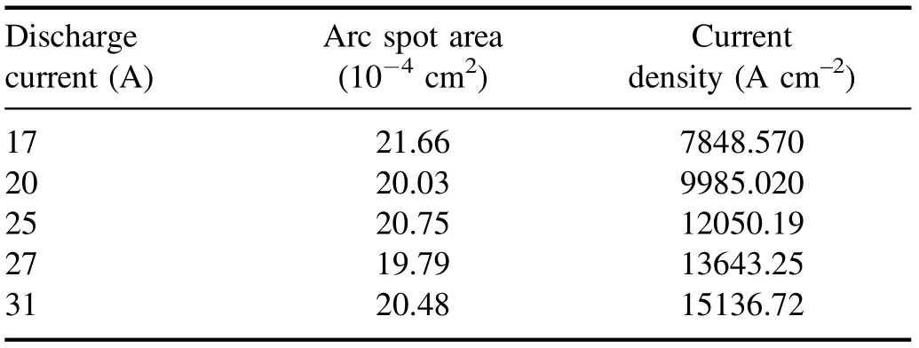
Table 1.Statistics table of discharge current, arc spot area and current density data.
The evaporation loss of the cathode can now be calculated simply by determining the relationship between temperature and saturated vapor pressure.Temperature is related to current density, and according to Richardson’s formula,electron emission current densityjeis:
where A is Richardson’s constant,which is 120 A cm-2K-2in rare Earth tungsten cathode,φis the effective work function of the cathode [19].
When the temperature is high enough, a space charge sheath and ionosphere form in the near surface region of the cathode [20].In the ionosphere, the cathode emits thermal electrons, and after accelerated by the cathode electric field,the part that does not occur Coulomb scattering participates in the ionization process of the plasma, and the energy balance in the ionization region is:
wherejiis the ion current density, k is the Boltzmann constant, e is the element charge, T is the spot temperature,Teis the electron temperature, X is the ionization energy of the plasma gas atom, the β coefficient is related to the electron scattering mechanism,the β coefficient of coulomb scattering is 3.2,Uiis the voltage drop in the ionization region,andUcis the cathode voltage drop.
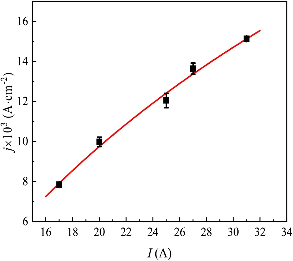
Figure 10.Relationship between discharge current and current density.
Uiis related to the temperature of the plasma, and its relationship is:
Without accounting for backscattered electrons, the total input current density j is:
In the space charge sheath, after the ions are accelerated in the electric field of the sheath, they neutralize with the cathode surface and complete the energy transfer, and this partof theenergy (kinetic energyandelectric potential energyis mainlyconsumed by electron emission energyand the remaining part is conducted from the insideof the cathode tothe cooling end.Therefore,theheat conduction density q of the cathode surface is:
where d is the cathode elongation.
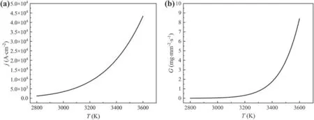
Figure 11.(a) Discharge current density versus temperature, and (b) evaporative flux density versus spot temperature.
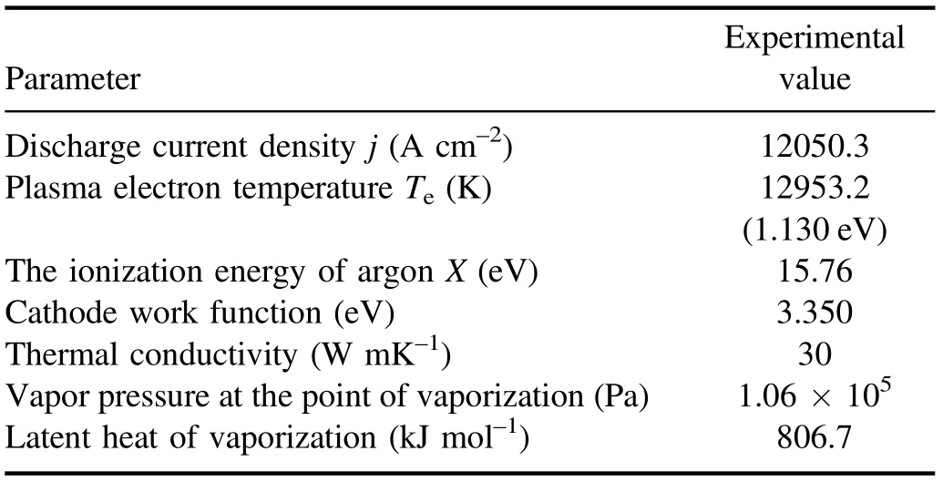
Table 2.Experimental operating parameters.
In steady state, the inside of the cathode is uniformly heated, and its heat flow Q is:
where S is the cathode surface area, λ is the thermal conductivity of the cathode material, andT0is the cooling end temperature.
By connecting equations (4) to (9), the relationship between total current density and spot temperature T can be obtained, as shown in figure 11(a).In the substitution of temperature T into equations (1) to (3), the relationship between the evaporation loss of the cathode and the temperature T at steady state is shown in figure 11(b).Thus, the mathematical relationship between total current density and temperature and evaporation flux is established.
The parameters calculated from the experiment are shown in table 2.When the discharge current is 25 A, the current density of the spot is 12050.30 A cm−2, the average spot temperature T of the cathode is 3267.00 K, the saturated vapor pressure in the spot is 0.18 Pa, the evaporation flux density is 1.47 × 10⁻⁴kg m-2s-1, the statistical spot area is 20.75 mm2, and the cathode evaporation loss in the steadystate process is 10.97 mg h−1.
4.3.Sputter loss calculation
Sputtering is a non-equilibrium process different from evaporation,in which high-energy particles eject cathode surface particles from a solid or liquid by bombardment.Since it is a collision process, particle sputtering occurs only when sufficient energy is transferred to overcome the surface bonding force, so a certain incident particle threshold energy is required.The medium ionic energy found in the MPDT cathode environment is close to the threshold energy, and although there are few theoretical studies on this energy domain,there is a good empirical scale law for sputtering near the threshold.
whereU0is the surface binding energy,M1andM2are the masses of argon ions and tungsten atoms, respectively, andζis the energy transfer factor.
Sputtering is characterized by yield, which is defined as the average number of target particles ejected per incident particle.Matusnami,Yamamura and Itoh et al[21]combined Sigmund’s linear collision cascade theory with a large number of experimental data to propose a semi-empirical formula for sputtering yield, which is in the specific form:
whereY(E) indicates that an ion with energy E (keV)bombards the cathode and can knock out Y cathode atomsαsandQsare empirical parameters;Sn(ε)is the nuclear blocking cross-section;Seε( ) is a dimensionless electron blocking cross-section,and its physical meaning is the probability of an incident particle colliding with the nucleus and electron.
This work only considers the elastic collision between incident particles and atoms that is the main collision of metal sputtering, and there are a few studies on the nonlinear sputtering theory caused by inelastic collision, so it is not within the scope of this paper.
K is the conversion factor from the elastic section to the stop section:
Reduced nuclear blocking cross-section is:
Dimensionless reduced energy is:
The reduced dimensionless electron blocking section is given by the LS equation [22]:
whereM1andM2are the atomic weights,Z1andZ2are the atomic numbers.
αsis only related to the mass ratio of the incident particle and the target atom, which is expressed as follows:
The values ofQsandU0depend on the property of the target material, for W,Qs= 0.77,U0= 8.900 eV.
Combined with the above formula,it can be seen that the sputtering yield depends on the energy carried by argon ions.
The sputtering fluxγspgenerated by the cathode material at the surface depends on the ion-to-surface fluxiΓand the sputtering yield Y:
The ion-to-surface flux can be approximated by random heat flux:
whereniis the density of Ar ions near the edge of the sheath,andviis the Bohm velocity of Ar ions.
At the plasma electron temperature studied, the neutral atomic density is negligible compared to the charged particle density, so the density of the plasma (ni) is equivalent to the electron density on the plasma-presheath boundary,thenican be calculated as
wherepis the ambient pressure (0.10 Pa).
The plasma separates it from the metal surface by forming a sheath,and there must be a transition layer between the electrically neutral main plasma and the non-electrically neutral sheath, allowing continuous ion flux while allowing ions to reach the presheath.The velocity at the sheath-tosheath boundary reaches the Bohm velocity.The Bohmvelocity can be calculated as
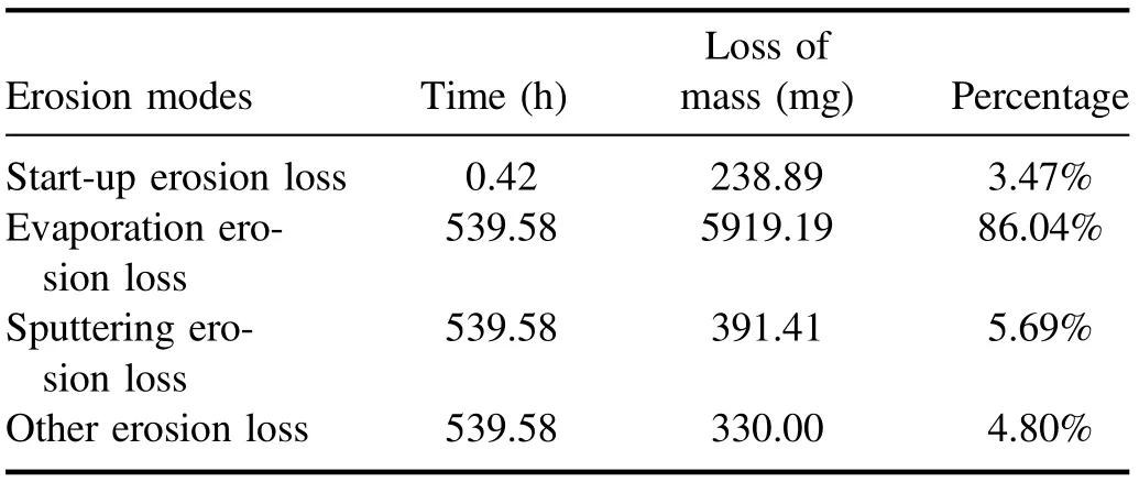
Table 3.Loss results under different erosion modes.
The ion density at the sheath boundary is
At the studied plasma electron temperaturethe low gas pressure makes the density of neutral atoms negligible compared to the density of charged particles.According to the collision-free sheath theory [23], the ion density at the cathode surface can be obtained as
whereMis the ion mass,φis sheath potential, it can be calculated as
where m is the electron mass.
According to the above equation,when an argon ion with an energy of 600.0 eV bombards the surface of the cathode,the effective sputtering area is 159.0 mm2,the sputtering yield is 0.51.Under the tested plasma temperature of 12953.2 K,the thermal movement velocity of ions is 1650 m s−1, the plasma density near the sheath layer is 1.98 × 10¹⁶m−3, the sputtering loss is 0.730 mg h−1.
It is clear that the ion sputtering loss accounts for only a small part in the steady-state erosion process, the loss of the cathode is mainly caused by evaporation, and the total loss rate of sputtering and evaporation is 11.70 mg h−1, which is less than the experimental value of 12.73 mg h−1, which is due to the experimental value to calculate the start-up loss.
5.Modeling results and comparisons
According to the theoretical model of steady-state erosion and sputtering, combined with the results of the start-up erosion experiment,the theoretical data of the starting loss(test value),evaporation loss and sputtering loss of the cathode in the 540 h erosion experiment are shown in table 3.In the 540 h erosion experiment, the start-up process totaled only 0.42 h, and the time accounted for 0.08%, but the loss accounted for 3.47%,which was equivalent to 20 h of steady-state erosion loss.The mass of evaporation loss in the steady-state erosion process was 5919.19 mg, and the loss accounted for 86.04%.In this process,even if the cathode is bombarded by plasma for a long time, the sputtering loss is less (only 391.41 mg), accounting for 5.69%.In addition, the sum of losses calculated according to the model is 6549.50 mg, while the experimental erosion loss is 6879.50 mg, and there is 330.00 mg of other erosion.This is due to the following reasons.First, there is liquid splashing during the start-up process and steady-state erosion,which is difficult to calculate in the erosion model.Second,the residual oxygen and water vapor in the working medium gas used react with tungsten at high temperature to form tungsten oxide,and the vapor pressure of tungsten oxide is higher than that of pure tungsten,which leads to a higher mass loss rate of tungsten.Third, the erosion model only considers the loss of tungsten,although the CeO2content is less,but the mass loss at high temperature is not counted.
6.Conclusions
In this work, we designed a 540 h erosion experiment and investigated the ignition times, corrosion rate and erosion mechanism of the cathode under vacuum conditions.The start-up erosion loss was measured and a static erosion model was established,and the theoretical service life of the cathode was inferred.The results show that the total erosion loss in the whole test process is 6879.50 mg, and the theoretical model calculates that there is an error of 330.00 mg between the total loss and the experimental value, which may be caused by tungsten liquefaction splash, evaporation of tungsten oxide,and erosion of added components.In the future, the error of the cathodic erosion model can be further reduced by optimizing the theoretical model.
杂志排行

Plasma Science and Technology的其它文章
- A laser-produced plasma source based on thin-film Gd targets for next-generation extreme ultraviolet lithography
- The effect of pulse voltage rise rate on the polypropylene surface hydrophilic modification by ns pulsed nitrogen DBD
- Comparative study on the degradation of phenol by a high-voltage pulsed discharge above a liquid surface and under a liquid surface
- Room-temperature degradation of o-xylene in simulated air using an online-regenerable plasma-catalysis reactor with low amounts of nanosized noble metals on Co3O4
- Enhanced surface-insulating performance of EP composites by doping plasmafluorinated ZnO nanofiller
- Closed corner divertor with B × ∇B away from the divertor: a promising divertor scenario for tokamak power exhaust