Enhanced surface-insulating performance of EP composites by doping plasmafluorinated ZnO nanofiller
2023-11-16QijunDUAN段祺君YanzeSONG宋岩泽ShuaiSHAO邵帅GuohuaYIN尹国华HaoouRUAN阮浩鸥andQingXIE谢庆
Qijun DUAN (段祺君), Yanze SONG (宋岩泽), Shuai SHAO (邵帅),Guohua YIN (尹国华), Haoou RUAN (阮浩鸥) and Qing XIE (谢庆),∗
1 State Key Laboratory of Alternate Electrical Power System with Renewable Energy Sources,North China Electric Power University, Beijing 1022062, People’s Republic of China
2 Hebei Provincial Key Laboratory of Power Transmission Equipment Security Defense, North China Electric Power University, Baoding 071003, People’s Republic of China
3 State Grid Changchun Power Supply Company, Changchun 130000, People’s Republic of China
Abstract
Keywords: plasma fluorination, ZnO nanofiller, epoxy resin, surface flashover, charge trap,density functional theory
1.Introduction
Epoxy composite is a pivotal material for high-voltage transmission equipment,large-pulse power devices,aerospace electronic devices,etc.Its insulation strength plays a vital role in the safe and stable operation of equipment[1-3].However,long-term high-voltage electrified operation will make the insulation defects on the material surface increasingly serious,which will lead to a flashover discharge fault of the gas-solid interface and threaten the safety of equipment operation [4,5].It is shown that adjusting the charge distribution on the surface of epoxy resin(EP)is an important means to improve its surface-insulating performance.Researchers have proposed a method to modify polymers by doping nanofillers,which has been proved to have a positive effect on improving the surface-insulating performance of EP composites [6, 7].

Figure 1.A diagram of the sub-model relations.
The introduction of nanofillers has two effects on epoxy composites: (1) the electrical properties of nanofillers are important factors affecting the insulation properties of composites; (2) the nano dielectric structure formed at the interface between the nanofiller and polymer matrix will produce a variety of special properties.In conventional modification research, insulating fillers, such as Al2O3and SiO2, are doped with EP, and a large number of charge traps are derived from the filler itself and the interface, so that the migration of carriers in the discharge process is constrained by potential wells [8, 9].However, with the expansion of research,it is found that there is a lifting limit by introducing deep traps to enhance flashover.An excessive deep-trap concentration will aggravate the charge accumulation effect and reduce the flashover voltage [10-12].He et al used a semiconductor nanofiller to build a functional coating on an insulator surface, which realized the directional induction of the surface charge and the uniform regulation of the surface electric field,and which provided a new modification idea for the improvement of the surface insulation[13].Nevertheless,at present, the doping modification of nano semiconductor fillers also faces interface problems, such as agglomeration[14, 15], poor compatibility and tunneling barriers [16, 17],which makes it difficult to effectively play the role of a semiconductor filler in promoting charge dissipation.
The surface modification of nanofillers is one of the effective methods used to improve their dispersion and compatibility in the matrix and to regulate the nano-interface structure.The traditional coupling-agent treatment method commonly used in industry has obvious effects on improving the interface compatibility, but it is difficult to improve the insulation performance of composite materials [18].Li et al proposed that attention should be paid to the important role of the nano-interface phase in the research of electrical property modification of composite materials based on previous studies[19].Considering the relative flashover discharge mechanism of nanofillers and their interfaces, we believe that optimizing their synergistic effect is an effective means to further enhance the surface flashover voltage of EP composites.The development of plasma-fluorination technology provides us with a new method of environmental protection and efficient nano-interface regulation [20, 21].The unique atomic structure of fluorine can promote the dispersion of filler and endow the interface phase with strong charge binding capacity.At the same time, the materials after plasma treatment often have significant chemical activity, which can promote the interface bonding between the filler and matrix[22].At present,research on the plasma fluorination of fillers is still in the initial stages, and the influence of fluorinated nanofiller on the flashover and trap characteristics of EP composites remains to be further explored.
In this work, ZnO nanofillers were fluorinated by plasma and doped with EP to study the effect of fluorinated ZnO on the surface flashover characteristics of EP composites.At the same time, traditional methods, such as direct doping of nanofillers and coupling-agent treatment, were used as the control group to analyze the advantages of plasma-fluorinated nano ZnO in improving the surface-insulating performance.In addition,combined with molecular dynamics(MD)simulation and density functional theory (DFT) molecular orbital calculation, the effect mechanism of fluorination modification on filler dispersion and interface traps was explored.
2.Experimental section
2.1.Materials
The materials for the preparation of cured EP included bisphenol A diglycidyl ether (DGEBA, E51), methyl tetrahydrophthalic anhydride (MTHPA, 504) and 2,4,6-tris(Dimethylaminomethyl) phenol (DMP-30), which were supplied by Shanghai Resin Co.Ltd.The 800 nm ZnO particles were purchased from Shanghai Chaowei Nano Technology Co.Ltd.The silane coupling agent(the chemical name is 3-Aminopropyltriethoxysilane (KH550)), ethanol(C2H6O, 99.7% purity) and deionized water were purchased from Aladdin Reagent Co.Ltd.Carbon tetrafluoride (CF4,purity 99.999%) and argon (Ar, purity 99.999%) were provided by Baoding Dongbao Industrial Gas Co.Ltd.

Figure 2.The DC surface flashover test platform.
2.2.Plasma fluorination of ZnO nanofiller
In this work, ZnO nanofiller was treated by DBD plasma discharge, and the platform is shown in figure 1.The plasma exciter is a high-frequency and high-voltage power supply with a central frequency of 50 kHz and a maximum voltage of 20 kV.The barrier dielectric is composed of a fixed quartz reactor with an inner diameter of 10 cm.The output terminal of the high-voltage power supply is connected to the upper terminal of the quartz reactor, and the bottom terminal of the reactor is grounded.There is a circular air hole of the same size on both sides of the reactor to ensure that the reaction gas is continuously introduced at a uniform speed.Ar and CF4are connected to the reactor through a gas flow controller,and the tail terminal is connected to the waste gas treatment device.In the process of treatment, an appropriate amount of ZnO nanofiller was evenly coated in the reactor,and the electrodes of the reactor were fixed.The gas flow rate was controlled as Ar 2.5 l min−1and CF40.4 l min−1,uniformly passed into the reactor,in which Ar was used as the protective gas and CF4as the fluorinated gas.After the gas flow was stabilized, the voltage of the plasma exciter was adjusted to 6 kV, and the frequency was 50 kHz.At this time,a stable plasma discharge could be formed in the reactor.The CF4gas and ZnO filler surface were bombarded to produce a large number of active groups, and then the fluorine-containing groups were grafted on the filler surface.The fluorination time was controlled at 30 min, and the treatment process was divided into three stages; each stage was treated for 10 min, and then the filler was re-mixed evenly before the next treatment.Finally,plasma-fluorinated nano ZnO (FZnO) was obtained.
To compare with traditional modification methods, ZnO nanofiller was grafted with KH550.Firstly, KH550 with a mass fraction of 10% of the filler, was dispersed in 30 ml of mixed solution of absolute ethanol and deionized water.The ratio of absolute ethanol to deionized water was 1:1.After fully stirring for 30 min, the filler was added to the solution and stirred for another 30 min.Then, the mixed liquid was ultrasonically dispersed for 10 min and dried at 60°C.The fully dried silane-coupling-agent-treated ZnO (KZnO) was taken out and ground for use.
2.3.Preparation of EP composite samples
ZnO nanofillers before and after modification were doped with EP at the mass fractions of 0%,5%,10%,15%,20%and 25%.The ZnO filler was first placed in a beaker and an appropriate amount of DGEBA was added, stirred at 60°C for 60 min, and then dispersed by ultrasonication for 30 min to fully disperse the filler.Then, the MTHPA and DMP-30 were added, and the mass ratio was DGEBA:MTHPA:DMP-30 = 100:80:1.The mixture was thoroughly stirred for 30 min, then degassed and poured into a stainless steel mold for gradient curing at 90°C/2 h + 120°C/8 h.After the composites were cured,they could be cooled and demolded to obtain the ZnO/EP composite samples.
2.4.Surface insulation performance
The samples were tested for surface flashover voltage in an atmospheric environment using a negative polarity DC power supply.The platform is shown in figure 2.A needle-needle electrode was used to simulate an extremely uneven electric field.The radius of curvature of the electrode tip was 0.2 mm and the electrode spacing was 7 mm.The experiments were carried out in a sealed stainless steel cylindrical chamber at 25°C and 30% humidity.The five samples of each experimental group were tested ten times, respectively, the voltage value at the instant of flashover was calculated and the average was taken as the final result.
2.5.Surface potential attenuation
To study the variation of the surface-charge dissipation rate and charge trap distribution characteristics of EP composites, the surface potential decay of the EP composite samples was tested[23].The experimental platform consists of a corona charging device, an active capacitance probe (Trek 3455ET), an electrometer and so on, as shown in figure 3.First, 7 kV voltage was applied to the needle electrode for corona charging on the sample surface,and the charging time was 1 min.Then,the active capacitance probe was used to monitor the dynamic potential data on the sample surface in real time.The data were monitored and stored by the electrometer,and the detection time was 30 min.The potential attenuation curve with time could be obtained by plotting the data.Since the surface potential of the sample after charging was controlled by the amount of charge,it was considered that the potential data could reflect the accumulation of surface charge [22].Furthermore, the charge trap levels and densities could be calculated using the isothermal surface charge decay method [10].
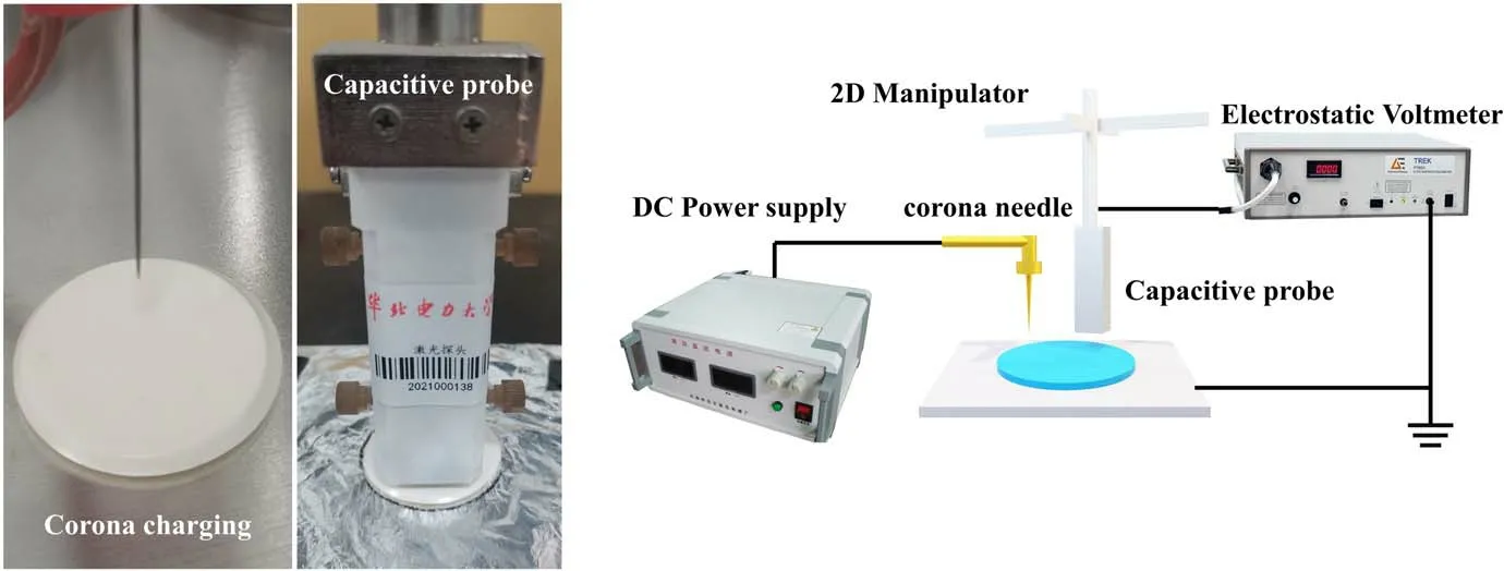
Figure 3.The surface-charge measurement platform.
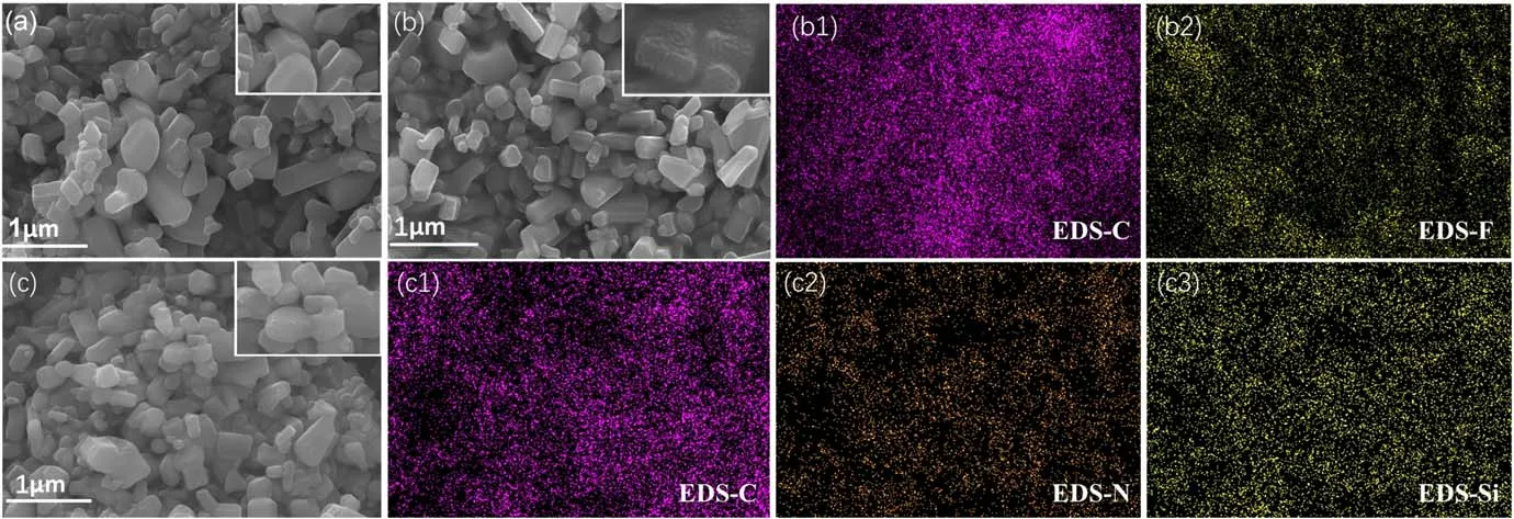
Figure 4.SEM and EDS characterization results of three ZnO nanofillers:(a)ZnO,(b)FZnO,(b1)carbon in FZnO,(b2)fluorine in FZnO,(c)KZnO, (c1) carbon in KZnO, (c2) nitrogen in KZnO and (c3) silicon in KZnO.
2.6.Dielectric properties
The dielectric constant and dielectric loss of epoxy composite were tested using an Agilent 4980 A.First, the surface of the specimen was gold sprayed,and the specimen was fixed with a fixture, ensuring that it fitted the sample completely.Then, the device was started, the test frequency was set to 40-200000 Hz and the test signal level was 5 mV.After the results were stabilized,the capacitance data and the dielectric loss were read, and the relative dielectric constant εrof the material could be calculated using the following equation:
where d is the thickness of the sample, S is the area of the electrode plate, the diameter is 3 mm and ε0is the vacuumdielectricconstant, which takes the value of 8.85 ×10⁻¹²Fm−1.
2.7.Characterization
The morphology of the modified nano ZnO was characterized using a scanning electron microscope(SEM), and the element distribution on the surface of the fillers was analyzed using an energy dispersive spectrometer(EDS).The effect of plasma fluorination on the crystal structure of the nano-ZnO filler was analyzed by x-ray diffraction (XRD).The effects of plasma-fluorination modification and coupling-agent modification on the surface chemical groups and components of the fillers were characterized using x-ray photoelectron spectroscopy(XPS).In addition, the cross sections of EP composites doped with different modified nano ZnO at 20% mass fraction were characterized by SEM, and the effects of different surface treatment methods on the dispersion of fillers were analyzed.
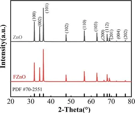
Figure 5.The XRD patterns of ZnO before and after fluorination.
3.Results
3.1.Morphology and composition analysis
The micro surface morphology of the ZnO nanofillers before and after modification is shown in figure 4, and it can be found that neither plasma fluorination nor coupling-agent treatment will significantly affect the particle size of the filler.The surface of the nano ZnO after plasma-fluorination treatment becomes rough, and a large number of granular protrusions appear.This is mainly because the plasma discharge process has a certain destructive effect on the surface of the filler and, at the same time, the fluorinecontaining group is also grafted on the surface.The surface of ZnO modified by the coupling agent has no obvious change.According to the results of EDS scanning, the fluorinecontaining groups are uniformly grafted on the surface of FZnO,and the C element content is obviously more than that of the F element, which indicates that the fluorine-containing groups mainly exist in the form of -CFx.CF4will be ionized in multiple stages during the plasma discharge process,and its reaction forms mainly include the following formulas [24]:
According to the principle of a chemical reaction, the difficulty in the ionization of F atoms will gradually increase;therefore, the fluorine-containing groups grafted on the surface of ZnO are mainly -CF3and -CF2−.The surface of the filler modified by the coupling agent is also evenly distributed with C, N, Si and other elements, which indicates that the coupling agent has been successfully grafted on the surface of the filler.

Figure 6.The XPS results of ZnO before and after surface modification.
To analyze the effect of plasma fluorination on the crystal structure of ZnO nanofillers, x-ray polycrystalline diffraction analysis was performed on ZnO before and after plasma fluorination, and the XRD patterns are shown in figure 5.Three main diffraction peaks,(100),(002)and(101),of ZnO appear at the diffraction angles 2θ = 31.67°, 34.42° and 36.24°, which are related to the hexagonal wurtzite position of ZnO.The diffraction peaks are completely consistent[25],the peaks are very high and sharp,and the half-width height is very small, indicating that ZnO has good crystallinity and no other impurity peaks.There is no obvious difference between the XRD patterns before and after fluorination,indicating that DBD fluorination only acts on the surface of the filler, does not change the crystal structure of ZnO and has no obvious effect on many properties of the filler itself.
The XPS results are shown in figure 6.It can be seen that the three ZnO fillers have Auger peaks at 471 eV and 494 eV,which are attributed to the Zn element, and there are valence electron peaks of the Zn element at 1021 eV and 1044 eV.There is a characteristic peak attributable to the O element at around 530 eV.The FZnO after plasma fluorination has an obvious peak at 685-688 eV, which is attributed to the F element, which also proves that the fluorine-containing groups are successfully grafted on the surface of the filler.The relative intensity of the O1s peak of the filler treated with the coupling agent increased, which also indicated that the coupling agent was grafted on the surface of the filler.
To compare the dispersion behavior of three nano ZnO in the epoxy matrix,we carried out SEM characterization of the cross section of EP composites,as shown in figure 7.It can be seen that both the unmodified ZnO/EP and the KZnO/EP modified by the coupling agent have a large epoxy continuous phase,which indicates that the agglomeration response of the filler is relatively serious.At the same time, it can be found that the filler modified by the coupling agent is often coated inside the resin matrix at the cross section, which also shows that the coupling agent has the best effect of improving the compatibility between the filler and the matrix.There is almost no large-area continuous phase of the resin matrix in the FZnO/EP composite, and there is no obvious agglomeration of the filler.It is shown that the fluorinecontaining groups on the surface of the filler can effectively improve the dispersibility of the filler.

Figure 7.SEM images of filler dispersion in EP composites: (a) EP, (b) ZnO/EP, (c) FZnO/EP and (d) KznO/EP.
3.2.DC surface flashover voltage
Figure 8 shows the flashover voltage of the ZnO/EP composites.The blue dotted line is the flashover voltage of pure EP,which is about 9.2 kV.It can be found that the ZnO nanofillers can effectively increase the flashover voltage of EP composites, and with the increase in the filler concentration,the flashover voltage first increases and then decreases.The effect of modified nano ZnO on the flashover voltage is better than that of unmodified fillers.When the concentration of the ZnO filler modified by the coupling agent is 10%, the flashover voltage of EP composite reaches 11.5 kV, which is 25% higher than that of pure epoxy.When the filler concentration of FZnO is 20 wt%, the flashover voltage reaches 12.1 kV, which is 31.52% higher than that of pure epoxy.In addition, we found that both ZnO and FZnO achieved the optimal modification effect at 20% mass fraction, while the optimal ratio of KZnO shifted to lower concentrations.We believe that this has a greater relationship with the interfacial interaction between the filler and the matrix.The coupling-agent grafting provides a better chemical linkage between the filler and the substrate.This not only fully exploits the semiconducting nature of ZnO nanoparticles, but also alleviates the interfacial barrier effect faced by charge migration.The presence of polar chain segments in the coupling-agent molecules also accelerates the charge migration, resulting in a significant increase in the charge dissipation rate, even at low concentrations [26, 27].
3.3.Surface charges and traps
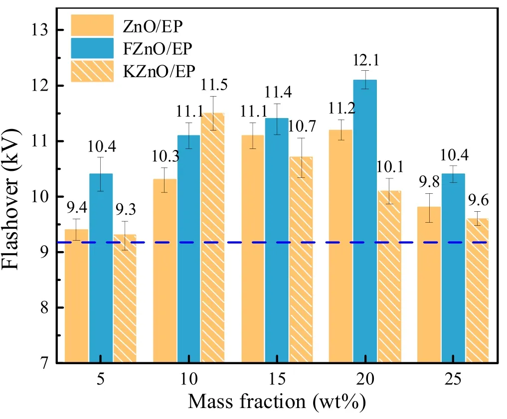
Figure 8.Flashover voltages of the EP composites.
Figures 9(a)-(c)show the normalized surface potential decay curves of the EP composites.It can be found that the charge dissipation ability of ZnO nanofillers does not improve significantly when the doping concentration is 5%.With the increase in filler concentration, the surface potential decay rate shows an upward trend.KZnO can effectively increase the decay rate of the surface potential under all concentration gradients.It proves that the interfacial bonding constructed by the coupling agent promotes the transport of charges,suppresses the Helmholtz effect at the interface and significantly reduces the charge transport barrier at the filler-substrate interface [16, 18].The contribution of FZnO to the decay rate of the surface potential is smaller than that of the other two ZnO fillers.When the filler concentration is higher than 10%, FZnO also significantly promotes the dissipation of the surface charge, but the proportion of potential dissipation is still much lower than that of the other two composites.When the filler concentration reaches 20%,we believe that the nano-ZnO particles will reach the percolation threshold at this concentration.The fillers are fully filled in the matrix and form a charge dissipation network, which makes the charge dissipation rate reach a peak, but the final normalized potential is still limited above 0.8.When the filler concentration continued to increase up to 25%, the charge dissipation was suppressed again, which we speculate is related to the agglomeration caused by the supersaturation of the filler and the stacking of the fluorinecontaining layer on the surface of the filler [10].
The trap distribution characteristics of the material are shown in figures 9(d)-(f).We analyze the trapping energy and binding stability of the material to explain the variation of the flashover voltage.It can be seen that when the filler concentration of ZnO/EP is 5%, the deep-trap energy level decreases slightly, but the trap density increases slightly.As the filler concentration continued to increase, the deep-trap energy level decreased from 1.03 to 0.98 eV, and the trap density also showed a decreasing trend,while the shallow trap density increased significantly.KZnO will introduce a large number of shallow traps into EP composites, and the energy level and density of deep traps will be significantly reduced.Meanwhile,with the increase in the filler concentration in the FZnO/EP composite, the deep-trap energy level showed a slight downward trend,reaching 1.0 eV at 20%concentration,but the deep-trap density had hardly decreased.At the same time, when the filler concentration is between 10% and 20%,the shallow trap density has a certain upward trend.
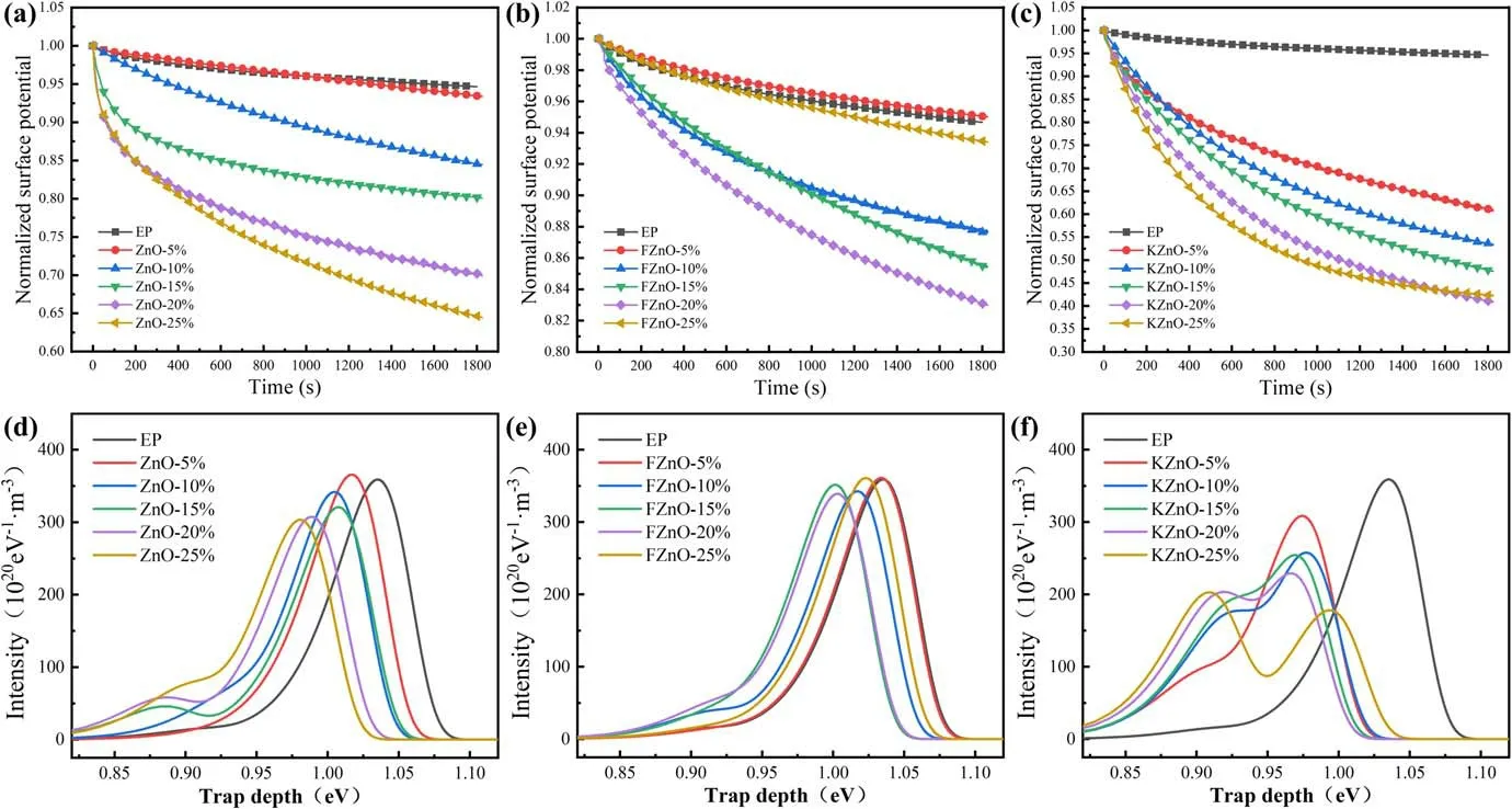
Figure 9.Surface-charge dissipation of the EP composites: (a) ZnO/EP, (b) FZnO/EP, (c) KZnO/EP and trap distribution of the EP composites, (d) ZnO/EP, (e) FZnO/EP and (f) KZnO/EP.
We believe that the unmodified ZnO lacks chemical bonding with the matrix,and only relies on a small amount of hydroxyl groups on the surface of the filler to form chemical bonds with the EP.There is a wide Helmholtz layer at the interface, which makes it difficult for charge to transition from the resin to the filler.With the increase in the nano-ZnO concentration, the filler gradually transitioned from the separated state to the continuous state in the composite, and the effect of the filler on the charge dissipation was gradually enhanced, so that the surface-charge accumulation was alleviated and the flashover voltage increased.After the coupling-agent treatment, a tight bond is formed between the filler and the epoxy matrix,and the carriers can be conducted from the matrix side to the filler side through the polar bond.This greatly accelerates the dissipation rate of the surface charge, and also makes the percolation threshold of KZnO significantly lower than that of the other two fillers.Although the fluorinated FZnO also builds the bond between the filler and the matrix,the fluorine-containing groups at the interface introduce deep traps,which can trap the carriers transmitted to the interface.This limits the secondary electron emission effect during the development of flashover.At the same time,with the increase in filler concentration,the ability of FZnO to accelerate the dissipation of charge and homogenize the electric field can also be exerted.Therefore, the flashover voltage of this system is increased most obviously.
3.4.Dielectric properties
The test results of the dielectric properties are shown in figure 10.It can be seen that all three composites have multiple polarization forms at low frequencies, causing oscillations in the dielectric constant curve, while the relative dielectric constant values gradually stabilize as the frequency gradually increases.Observing figure 10(a), it can be seen that the dielectric constant and dielectric loss of ZnO/EP show a rising trend with the increase in the nano-ZnO doping concentration.This is directly related to the semiconductor nature of the filler itself, and the dielectric constant of ZnO is higher than that of crosslinked EP.Therefore, with the increase in the filler concentration,the relative dielectric constant and dielectric loss of the composite also increase.In addition, due to the uneven distribution of ZnO nanoparticles in the epoxy matrix, a large number of dangling chain segments are easily formed at the interface.These chain segments are all strongly polarized and form a strong dipole polarization under the action of an external electric field,so the rise in the dielectric constant tends to increase with the increase in the filler concentration [27].From figure 10(b),it can be seen that the effect of FZnO on the dielectric constants of the EP composites shows an overall trend of reduction, and the dielectric loss is lower than that of the untreated filler.Meanwhile,it can be found that as the filler concentration increases, the dielectric constant of the system exhibits a W-shaped trend of change, and the dielectric loss increases and then decreases, before finally increasing.This can be approximated as a sinusoidal-like variation pattern.According to the multi-core model, the nano-interface region can be divided into a bonded layer,a bound layer and a loose layer, and the electrical characteristics exhibited by each layer interface region have significant differences.Based on the interface model theory mentioned above, we proposed a dielectric model derived from the interface overlap of nanofillers in [10].That is, ideally, the nanoparticles are uniformly dispersed in the epoxy composite material, and the resin matrix can be regarded as a uniform medium.When the interfacial layer between particles overlaps step by step with the increase in the packing concentration,the nano interface in the overlapping region plays a dominant role in the polarization of the composite.When the different interface layers between particles exhibit a gradual overlapping effect as the filler concentration increases,the nano interfaces in the overlapping region will successively dominate the polarization effect of the composite material.Therefore, the macroscopic electrical properties of composite materials exhibit a periodic variation pattern similar to a sine wave.This effect is also observed in the KZnO/EP system,as shown in figure 10(c).The difference is that the dielectric constant of the KZnO/EP is higher overall than that of the pure epoxy system.Although the dispersion and compatibility of the filler are improved after modification by the coupling agent,the coupling-agent molecule introduces a large number of polar chain segments at the interface, thus enhancing the dipole polarization and intercalation polarization in the interfacial region,leading to an increase in the dielectric constant [10, 28].

Figure 10.Dielectric properties of the EP composites: (a) ZnO/EP, (b) FZnO/EP and (c) KZnO/EP.
4.Analysis and discussion
4.1.Interface interaction
In the research of nano-modification of composite materials,the agglomeration effect of fillers is the critical difficulty that affects the modification effect.In particular, in terms of the insulation performance, the agglomeration will lead to the uneven distribution of the interface region [9].The surface energy of nanofillers is high, and it is often difficult to be compatible with organic matter, which leads to the formation of aggregates in the polymer.In this work,the MD simulation method was used to calculate the effect of different surface treatments on the interfacial energy between ZnO nanofillers and the epoxy matrix.
First, the monomer molecules of EP and acid anhydride were constructed based on Materials Studio software,and the two monomer molecules were put into the periodic box according to the numbers 80 and 40.Then, the geometry of the uncrosslinked EP anhydride system was optimized to make the molecular structure and chain segment distribution more reasonable.Under the conditions of 298 K and 0.1 MPa,NPT and NVT optimizations of 200 ps were carried out,respectively, to obtain the EP model.To further investigate the interfacial interaction between the crosslinked EP and nano ZnO,we constructed a molecular model of 30 DGEBA,70 MTHPA and 10 DGEBA-MTHPA (after one crosslinking reaction,which acts as a chain initiator),and a crosslinked EP model with 90% crosslinking degree was obtained by script for multi-stage crosslinking; the detailed method can be obtained in our previous paper [29].The crosslinking degree here refers to the consumption rate of the cyclic oxygen group.Later,the crystal structure of ZnO was introduced,and the unit cell was cleaved to obtain the 001 plane; then the supercell was constructed to obtain a ZnO model containing 648 atoms.By grafting fluorine-containing groups and coupling-agent segments on the 001 surface, the surface of the modified filler was simulated.Further, the build-layer function was used to build the interface model between the filler and EP before and after crosslinking.A vacuum layer with a thickness of 30 Å was set above the model to eliminate the influence of periodicity.Geometry optimization and 200 ps NVT optimization were performed on the interface model.The calculation step was 1 fs, and a frame file was output every 1 ps.Then, the interface binding energy of different models was calculated.The interface energy of the last 50 frames was selected, and the average value was taken as the final data.The interface interaction energy can be described by equation (3):
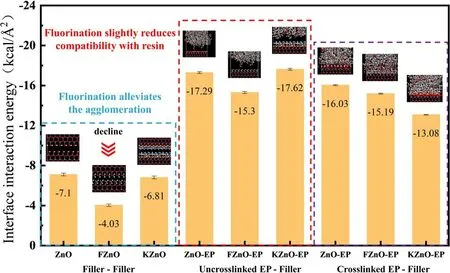
Figure 11.The interface interaction energy.
The calculation results are shown in figure 11.It can be found that the interfacial interaction between FZnO nanoparticles is significantly lower than that of couplingagent-modified and unmodified nano ZnO.We believe that fluorine-containing groups are grafted on the surface of FZnO, and the special structure of the fluorine atom makes it firmly bind the valence electrons near the nucleus.This endows it with extremely low surface energy, making the interaction energy between fluorine-containing groups much lower than that of general groups.When two adjacent FZnO are close to each other, the high surface energy and mismatching points are covered by fluorine-containing groups, and the affinity between the particles turns into mutual repulsion.The dispersibility of FZnO in the EP matrix is greatly improved.At the same time, we calculated the interaction energies between the ZnO nanofillers and the uncrosslinked EP.It can be found that the interaction energy between FZnO and EP was slightly decreased, while the modification of the coupling agent could improve the affinity between KZnO and the EP matrix.This is also attributed to the relatively reduced sites for the affinity due to the introduction of fluorine-containing groups, and the lower surface energy of the fluorine-containing groups also weakens the interfacial interaction.It should be pointed out that in the actual preparation process, since the fluorine-containing groups are grafted on the surface of ZnO by plasma means,the filler surface will have a sustainable reactivity.This promotes the bonding between the fluorinated filler and the epoxy matrix,and also improves the compatibility of the filler and the EP.Further, we analyzed the interfacial interactions between the three ZnO particles and the crosslinked EP.It can be found that the interfacial interaction energy between the crosslinked EP and the three ZnO nanoparticles is significantly reduced compared with the uncrosslinked system.This is mainly due to the fact that the highly reactive epoxy and anhydride groups in the crosslinked EP system are consumed; therefore, the van der Waals interaction and hydrogen bonding at the interface are weakened, and the interfacial interaction energy also decreases.It can also be found that the interfacial interaction energy between FZnO and the crosslinked EP is slightly reduced compared to that of the uncrosslinked EP, and is still lower than that between the crosslinked EP and ZnO.In addition, a paradoxical and significant decrease in the interfacial interaction energy between KZnO and crosslinked EP was observed.It is believed that the coupling-agent molecules on the surface of KZnO have stronger affinity, mainly with epoxy and anhydride groups.However, the EP model after crosslinking has a significant reduction in epoxy groups and anhydride groups, which are replaced by crosslinked bonds, such as ether and ester groups.Therefore, the interfacial interaction energy between the two is also reduced.
4.2.Effect of electric field on bond length and bond angle
To explore the influence of an external electric field on the bond lengths and bond angles of typical chemical bonds in different systems,we constructed models of epoxy composites with the mass fraction of the model controlled at 20%.The ZnO crystal model was first imported, and a spherical particle with a diameter of 10 Å was cut out by the build nanocluster function; then, three different kinds of modified groups were grafted on the surface of the model.The filler model was further geometry optimized, and a cubic periodic box with a side length of 48 Å was constructed by the Amorphous Cell module.Subsequently, the molar ratio of 4:9:1 of DGEBA,MTHPA and DGEBA-MTHPA was added into the box using the packing function,and the initial density of the box was set to 0.8 g cm−3to obtain a system containing 55 DGEBA, 124 MTHPA, 14 DGEBA-MTHPA and ZnO fillers.After geometry optimization and dynamic optimization of the model,the crosslinking process was performed using a script, and finally the crosslinked EP system containing different modified ZnO could be obtained [29].The optimization process force fields were all selected as universal with a time of 50 ps, and the crosslinking degree of the final obtained composite system model was controlled at 90%.The electric field in the X direction was further applied to the models, and the NVT dynamic processes were carried out for 100 ps at different field strengths in steps of 1 fs.The bond length and bond angle parameters of typical chemical bonds were extracted from thelast 20 frames of the obtained process files,and the final results were obtained by averaging.

Table 1.The changes in bond length in the epoxy composite model.
The calculated bond lengths of C-C attributed to the methyl side chain, C-O attributed to DGEBA, and C=O attributed to MTHPA in the epoxy composite model are shown in table 1.It can be seen that the applied electric field affects the parameters of the chemical bonds inside the crosslinked epoxy molecules.The bond lengths of typical chemical bonds in all three systems fluctuate to some extent with increasing electric field strength.However, since the crosslinked EP is a large molecule with a three-dimensional network, the chain segments within the molecule are closely linked and interact with each other,which makes it less effective to be influenced by external electric fields.From the data in the table,it can be seen that the bond lengths of the three typical chemical bonds in the FZnO/EP system are less affected by the electric field compared to the other system models, while the variation of the chemical bonds in the KZnO/EP system is relatively large.It is deduced that the fluorine atoms have a strong binding effect on their outer electrons, and the changes in their chemical bonds under the action of the external electric field are smaller.Therefore, the behavior of fluorinated filler molecules,such as polarization and motion,has less influence on the epoxy molecular model.On the other hand, ZnO and KZnO contain more polar bonds, which are very prone to changes such as stretching and vibrating under the action of the external electric field,and this behavior will have a greater impact on the adjacent epoxy molecules.The bond angles of three typical chemical bonds, such as C-C-C attributed to the two methyl groups in DGEBA,C-C-C-2 attributed to the methyl side group of MTHPA, and C-C=O attributed to the crosslinked bond, are shown in table 2.It can be found that the bond angle of the FZnO/EP system changes greatly under the electric field, while the bond angle of the KZnO/EP system changes slightly.We believe that the change in bond angle is mainly dominated by the shift of chemical bonds and the rotation of groups.The free-volume space inside the system will have an important impact on this behavior.However, the FZnO/EP and ZnO/EP systems will derive a large free-volume space at the interface due to the short chain segment of the group grafted on the filler surface, which is conducive to the movement of the group.Meanwhile, the molecular chain segment of the coupling agent is long,and it is easy to fill the gap at the interface,thus reducing the movement space of the epoxy molecule.Therefore, the chemical bond angle of the epoxy molecule in this system is less affected by the external electric field.
4.3.DFT calculation of molecular orbitals
To further analyze the influence mechanism of charge traps,we selected the three molecular segments between the ZnO fillers and the matrix as the object, and calculated the molecular orbital energy levels using a quantum chemical method.Since both sides of the three interface segments are ZnO and EP, the two ends of the molecular segment are hydrotreated, and only the interface molecules are studied[30].Based on the Dmol3 module, PBE was used as the exchange correlation functional, and the DFT was calculated using the generalized gradient approximation.The calculation took into account the effect of electron polarization,and used the dual numerical plus polarization basis set for the calculation, while the numerical integration adopted a mesh size of fine quality[31].In the calculation process,firstly,the molecule was geometrically optimized.Then, the 50 ps NVT was optimized,and then the molecular orbital energy levels of the three chain segments were analyzed.The results are shown in figure 12.The orbital energy levels of molecular segments in the interface region include the lowest unoccupied molecular orbital (LUMO) and the highest occupied molecular orbital (HOMO).The LUMO acts as a trap site to trap electrons inside the material, and the HOMO acts as a hole trap site.The midpoint of the two energy levels is the Fermi level.After being excited, the electrons of the HOMO will transition to the LUMO to obtain mobility.The energy required for the transition is the energy gap(Egap).The energy gap between the LUMO and HOMO can reflect the electronic transition ability.In the research of insulating materials, Egapis considered as a form of trap existence [30].The frontier orbital energy gap of the model is:
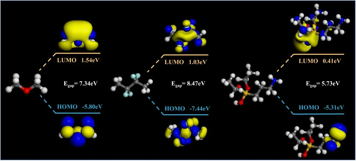
Figure 12.The molecular orbital energy gap in the interface region.
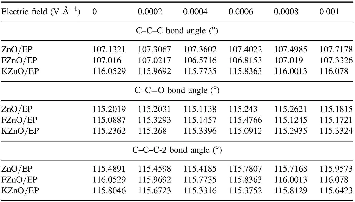
Table 2.The changes in bond angle in the epoxy composite model.
It can be seen from the calculation results that the surface of the unmodified filler forms bonds with epoxy with a small number of hydroxyl groups, and its energy gap is basically 7.34 eV.However, it should be noted that the surface of the untreated filler contains only a very small number of hydroxyl groups; therefore, there are often more vacuum bands at the interface,which makes it more difficult for carriers to migrate between the filler and the matrix.The KZnO is connected to the epoxy through the coupling-agent segment, and the energy gap is much smaller than that of untreated filler due to the existence of polar groups; therefore, the density of the shallow traps inside the composites is greatly increased.The FZnO is bonded to the epoxy matrix through the fluorinecontaining segment, and the fluorine-containing group increases the Egapof the segment significantly, thereby introducing a large number of deep traps at the interface.However, at the same time, the fluorine-containing segment also provides more bonding sites between the filler and the matrix;therefore,the interface trap density is relatively stable,and the charge can still be transported through the segment.The energy required for the carriers is still reduced compared to the direct transition from the epoxy side to the filler side.
4.4.Mechanism of filler fluorination
Plasma-fluorinated ZnO significantly increases the DC surface flashover voltage of EP composites,and its modification effect is better than that of traditional coupling agents.We deduce that this mainly depends on two effects.First, the plasmafluorination treatment improves the dispersion and compatibility of the fillers, and the deep traps introduced at the filler interface suppress the discharge development and secondary electron emission [32].The ZnO filler with nonlinear semiconducting properties mainly plays the role of preventing charge accumulation and homogenizing the electric field inside the EP composites,which has been proved to have a significant effect in several studies[11,33].However,compared with the EP matrix,semiconductor fillers often have higher conductivity and dielectric constants, and the agglomeration effect of nanofillers makes it difficult to effectively control the percolation behavior.At the same time, the obvious electric field distortion will be caused at the interface of the fillermatrix-vacuum due to the significant dielectric difference,which makes the three junctions become a weak link in the flashover development,and it is easy to excite a large number of secondary electrons under the action of initial electrons[34].However, the fluorinated filler introduces a large number of fluorine-containing groups in the interface area.These fluorinecontaining groups provide a large number of deep traps,which effectively inhibits the discharge development in the interface area and improves the insulation strength at the interface.On the other hand, the plasma treatment enables the fluorinecontaining groups on the surface of the filler to further react with the EP,thereby establishing a chemical bond between the filler and the resin.This optimizes the multi-core structure at the interface,and fixes the fluorine-containing chain segments in the bonded layer and the bound layer,in order to regulate the traps at the interface to maintain a higher energy level and density.The effective concentration range of the semiconductor nanofillers has also been expanded.At the same time, the interface bonding cooperation also avoids the interface barrier;when the filler concentration reaches a certain threshold, the charge dissipation rate on the surface of FZnO/EP will also be significantly increased.This provides a good path for the dissipation of local charges on the composite surface and alleviates the field strength distortion effect caused by charge accumulation [35].The synergistic effect of fillers and fluorinated interfaces improves the surface insulation performance of EP composite materials.
5.Conclusions
In this work,ZnO nanofillers were fluorinated by plasma,and the advantages of improving the flashover performance of EP composites were further studied.The results show that the plasma-fluorination treatment can graft fluorine-containing groups on the surface of nano ZnO and improve the dispersibility of ZnO in an EP matrix.Compared with unmodified ZnO and coupling-agent-modified ZnO, plasmafluorinated ZnO has a higher flashover enhancement effect.When the concentration of FZnO is 20%, the DC flashover voltage of EP composites increases by 31.52%.At the same time, it is found that the filler fluorination can reduce the dielectric constant and dielectric loss of the epoxy composite.Compared with KZnO/EP, FZnO/EP contains more deep traps at the interface,which inhibits the emission of secondary electrons and hinders the development of flashover discharge.At the same time, the fluorination modification also establishes a chemical bond between the filler and the EP,which can accelerate the rate of charge dissipation in the charge accumulation area to a certain extent.The synergistic effect between the filler and filler interface has positive significance for the development of the process of inhibiting the flashover discharge of EP composites, which also provides new ideas for the subsequent research on nanomodified insulating dielectrics.
Acknowledgments
This work is supported by Beijing Natural Science Foundation (No.3222057), and National Natural Science Foundation of China (Nos.52277147 and 52007065).
猜你喜欢
杂志排行
Plasma Science and Technology的其它文章
- 3D fluid model analysis on the generation of negative hydrogen ions for negative ion source of NBI
- Enhancing surface adhesion of polytetrafluoroethylene induced by two-step in-situ treatment with radiofrequency capacitively coupled Ar/Ar+CH4+NH3 plasma
- Etching characteristics and surface modification of InGaSnO thin films under Cl2/Ar plasma
- Pulsed gas-liquid discharge plasma catalytic degradation of bisphenol A over graphene/CdS: process parameters optimization and O3 activation mechanism analysis
- A homogeneous atmospheric pressure air plasma in a 10mm gap based on a threeelectrode configuration
- Effect of gas flow on the nanoparticles transport in dusty acetylene plasmas
