A Fine Synchronization Method for Coherent Fast Frequency Hopping
2023-11-06XuanheYangWeikeZhangShixunLuoChangLiXiaqingMiaoAihuaWang
Xuanhe Yang ,Weike Zhang ,Shixun Luo ,Chang Li ,Xiaqing Miao,* ,Aihua Wang
1 School of Information and Electronics,Beijing Institute of Technology,Beijing 100081,China
2 96901 People’s Liberation Army(PLA)Troops,Beijing 100000,China
3 School of Cyberspace Science and Technology,Beijing Institute of Technology,Beijing 100081,China
*The corresponding author,email: xqmiao@bit.edu.cn
Abstract: Coherent fast frequency hopping (CFFH)is attracting growing attention owing to its good antijamming performance and the coherent combining ability.However,compared with the conventional non-coherent fast frequency hopping,CFFH requires a more precise system synchronization.In this paper,we propose a new fine synchronization algorithm for CFFH.This algorithm consists two stages,namely,open-loop stage and closed-loop stage.In the openloop stage,a grid-based search parameter estimation method is proposed.In the closed-loop stage,we construct a fully coherent phase-locked loop (PLL) and a delay-locked loop (DLL) with decoding feedback structure to perform further fine estimation of the system clock skew and time delay,respectively.Moreover,we analyze the effect of the search parameter settings on the estimation error and derive the root mean squared error(RMSE)of estimates in the steady state of the closed-loop stage.Finally,through simulation,the RMSE performance are compared with the corresponding Cramer-Rao low bound(CRLB)and conventional code loop estimation to show the effectiveness of proposed algorithm.
Keywords: fast frequency hopping (FFH);spread spectrum communication;fine synchronization
I.INTRODUCTION
As one of the most important physical-layer secure transmission techniques,fast frequency hopping (FFH) is known for its significant low interception probability (LPI) and anti-jamming capabilities,which has been widely adopted in numerous applications [1].Typically,the conventional FFH systems employ a non-coherent modulation and combining technique for the sake of simple implementation [2–5].However,the signal-to-noise ratio (SNR) of each hop decreases as the frequency diversity increases,the non-coherent combination introduces a rapidly increasing non-coherent loss at the hop-level,and thus significantly deteriorates the receiver sensitivity performance.Consequently,the large diversity gain for anti-jamming reception and high receiving sensitivity for low SNR reception become a pair of trade-off,which limits the application of FFH systems.In contrast to the non-coherent FFH,coherent FFH(CFFH)scheme was proposed in the 1990s by L.Milstein[6–8].In such scheme,the signal possesses the coherent inter-hop carrier phase,and the receiver can resort to a coherent combining of hops.Recently,CFFH is gaining renewed attention thanks to the fast development of direct digital synthesis(DDS)chips[9,10]and new channel estimation methods[11–13].Some new application scenarios for CFFH have been explored,such as tracking,telemetry and control (TT&C) [14],unmanned combat aerial vehicles(UCAV)swarms[15],industrial internet of things (IIoT) [16].Also,some new implementations and experiments have been proposed in[17,18].
To achieve successful frequency hopping,the transmitter and the receiver must be tightly synchronized,especially in the FFH systems [19].In other words,synchronization techniques are crucial in FFH communications.Compared with the conventional non-coherent FFH systems,CFFH technique requires higher estimation precision of time delay and frequency deviation due to the coherent combining of multiple frequency channels[8,6,20].Typically,the synchronization process for frequency hopping systems consists of two stages,i.e.,coarse synchronization and fine synchronization[21].In the coarse synchronization stage,symbol-level system synchronization is completed by the receiver,which includes the synchronization of frequency hopping patterns and coarse estimation of time delay and frequency deviation.In the fine synchronization stage,the receiver performs fine estimation of the signal time delay,frequency deviation,and carrier phase based on the output of coarse synchronization.The coarse synchronization methods of CFFH have been well investigated in many studies,for instance [21–24],whereas there are only a few studies conducted on the fine synchronization of CFFH.
Conventional algorithms for fine synchronization of signals are divided into two main categories [25] :open-loop and closed-loop algorithms,depending on the implementation structure.Open-loop algorithms have the advantage of fast estimation,but poor estimation accuracy and adaptation to parameter changes;closed-loop algorithms,on the contrary,have high accuracy and can track parameter changes,but convergence time is usually long.[26] proposed an openloop synchronization method for hybrid CFFH and direct sequence (CFFH/DS) spread spectrum system.This approach performed parameter search in the twodimensional plane of Doppler and code delay,and eliminated the Doppler frequency dispersion (DFD)between different frequencies by using keystone transform.In[27],an estimation method based on the randomness of multi-symbol frequency hopping patterns was proposed for the problem of integer ambiguity in CFFH/DS Doppler estimation when the number of hops was limited.It should be noted that the algorithms in [26] and [27] employed differential coherent accumulation at the symbol-level and hop-level,respectively,which would inevitably cause a loss of SNR.For closed-loop algorithms,a CFFH/DS tracking system based on delay-locked loop (DLL) and phase-locked loop(PLL)was designed in[8,6].However,only the case of one hop in a symbol was considered,and the authors provided few insights of combining characteristics among inter-symbol hops.A noncoherent DLL-based time delay tracking structure for CFFH/DS with multi-hop in a symbol was proposed in[14],nevertheless,frequency deviation was not considered in that structure,which may not be suitable for practical implementation.In addition,all the above studies utilized the code-word correlation property of DSSS(direct sequence spread spectrum)in time synchronization,which was not applicable to non-DSSSaided CFFH systems,and thus there was a generalization problem.
Regarding above issues,in this paper,we propose a novel fine synchronization algorithm for CFFH systems.The proposed algorithm is suitable for scenarios where the hop rate is much higher than the symbol rate,i.e.,multiple hops within one symbol duration.Moreover,the proposed algorithm also allows accurate tracking of the frequency deviation generated by clock skew.The main contributions of this paper are summarized as follows:
1.First,a novel two-stage clock skew and time delay estimation method is proposed for CFFH systems.In the open-loop stage,a coherent grid search method based on the maximum likelihood criterion is proposed.Then,the effects of the search parameters on the residual estimate error are analyzed.In the closed-loop estimation stage,we develop a DLL structure to estimate/track the frequency deviation and carrier phase.Then,the received time delay is finely estimated based on the proposed DLL structure.Besides,to achieve coherent accumulation at the symbol-level,a decoding feedback scheme is employed to depolarize the symbols of the loop input during the closedloop stage.For each stage in the algorithm,this paper presents detailed structures of practical implementations.
2.Second,we innovatively exploit the characteristics of phase differences among CFFH signal carriers to design the DLL structure.Different from conventional DLLs that based on the phase discriminator of time-domain correlated waveforms in a single carrier [28–30],the proposed DLL structure utilizes the phase differences of time delay among different hops to construct the early and late branches.Therefore,the phase discrimination process no longer depends on the time domain waveform on a single hop as in CFFH/DS but on the phase of all frequency channels.Consequently,the delay estimation accuracy of the system is proportional to the overall frequency hopping bandwidth.
3.Finally,the overall performance of the proposed algorithm is analyzed and extensive simulations are conducted.For the open-loop stage,the performance comparison of the correct detection probability and the root mean square error(RMSE)of estimates with different search parameters are presented.For the closed-loop stage,the RMSE of the estimates in the steady state is also derived and verified in the simulations.To verify the effectiveness of the proposed algorithm,the Cramer-Rao lower bound (CRLB) of the corresponding parameter estimation is also derived as a benchmark.The approximate expressions of the CRLB and the RMSE in the steady state are given by numerical calculations.
The rest of the paper is organized as follows.In Section II,we introduce the system model of CFFH with clock skew and time delay.Subsequently,the parameter estimation method based on grid-based open-loop searching is proposed in Section III.In Section IV,we propose the fine estimation method in closed-loop stage and the detailed structure of the loop implementation.Moreover,the RMSE of estimates is also derived in Section IV.In Section V,we derive the CRLB of parameter estimation of the CFFH system.In Section VI,simulation results of the proposed algorithm are presented.Finally,Section VII concludes this paper.
Notations:We use bold uppercase and lowercase letters to represent matrices and vectors,respectively.And(·)T,(·)H,(·)-1denote the transpose,conjugate transpose (Hermitian),and inverse,respectively.We use E{·}to denote expectation,ℜ[·] to denote real part andℑ[·]to denote imaginary part.Given a matrix
A=[a1,a2,a3,...,aN]∈CM×N,we use[A]m,nto denote the(m,n)th element ofA.We also use[A]m,:and [A]:,nto denote themth row andnth column ofArespectively.Besides,we define the vectorization operation ofAas vec(A)=The symbol⊙stands for the hadamard product andmeans the rounding down ofx.diag(x) represents the diagonal matrix with the diagonal specified by vectorx.In this paper,1Nand 0Nare used to represent all-one column vector and all-zero column vector of lengthN,respectively,andx=[M:N]denotes the row vector from integerMto integerNin steps of 1.Furthermore,sinc(x) denotes the sampling function,which is defined as sinc(x)=denotes the impulse function.
For facilitate reading,some frequently parameters representation of system are listed as following:
II.SYSTEM MODEL
In this work,we consider a CFFH system [12]withK(K≫1) available frequency channels and zero intermediate frequency (ZIP).LetfM=[f1,...,fk,...,fK]T∈RK×1denotes the frequency channels,in which
where ∆frepresents the space between two adjacent frequency channels infM.To achieve the maximum frequency-domain diversity[31],we assume that each symbol traverses allKfrequencies offMand occurs once at each frequency,and under this assumption,Kalso denotes the number of hops per symbol.For theuth symbol,the frequency hopping patternis a random arrangement of elements infM.Define Ψu(k)as the mapping function fromfMtof(u),i.e.,
Moreover,the inverse mapping function fromfMto theuth symbolkth hopping frequency is denoted as(k).
It is assumed that the clock skew exists but no relative motion between the transmitter and the receiver,and the channel fading is flat.Then,the received signal with clock skew factorεis expressed as
whereArepresents the amplitude of the received signal,b(u)∈{+1,-1}is theuth symbol.TheThandTs=KThdenote the hop duration and symbol duration,respectively.fcis the center frequency of radiofrequency (RF) signal,and we assume thatfcis an integer multiple of symbol rateRs=.Furthermore,φ0is the residual phase introduced by the RF oscillator.τis the time delay of start time between the received signal and the frequency hopping synthesizer at the receiver.Note thatτis much smaller thanThafter coarse synchronization.Finally,the narrow-band assumption is considered,i.e.,fK≪fc.
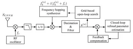
Figure 1.Block diagram of the receiver.
whereµis the estimation error ofandhu,k(τ,µ) is the result of correlated reception of the baseband signal for each hop,denoted as
Furthermore,we adopt the common assumption of bounded error and time delay estimation in coarse synchronization[21],i.e.,
where the integerM>1 corresponding to the number of code slices per hop in[21].
It is worth noting that the DS is not employed in this paper.However,the coarse synchronization can be done according to the CFFH/DS systems in [21].Without loss of generality,we assume ∆f==MKRs.Then
The received signal in(6)can be rewritten as
III.GRID-BASED OPEN-LOOP SEARCH
In this section,we propose a parameter estimation method forµ,τ,andφbased on pilot-aid open-loop search.Without loss of generality,we assume thatb(u)=1 for the pilot sequence and the length of the pilot sequence isQpl.Then the reception matrix is given by
The reception matrix for the signal components is expressed as
Based on the maximum likelihood criterion and Gaussian distribution property ofn(u),the likelihood function estimated forµ,τ,φcan be written as
wherezpl=vec(Zpl)∈andrpl=vec(Rpl)∈.By simplifying (13),it is evident that maximizingL(µ,τ,φ) is equivalent to searching for theµ,τ,φto maximize the following function
Noting that in(12),µandτare relatively independent within a symbol.Moreover,φonly imposes a fixed phase rotation on signal.The estimation process can be accessed by the grid-based search shown in Figure 2.The detailed steps are as follows:
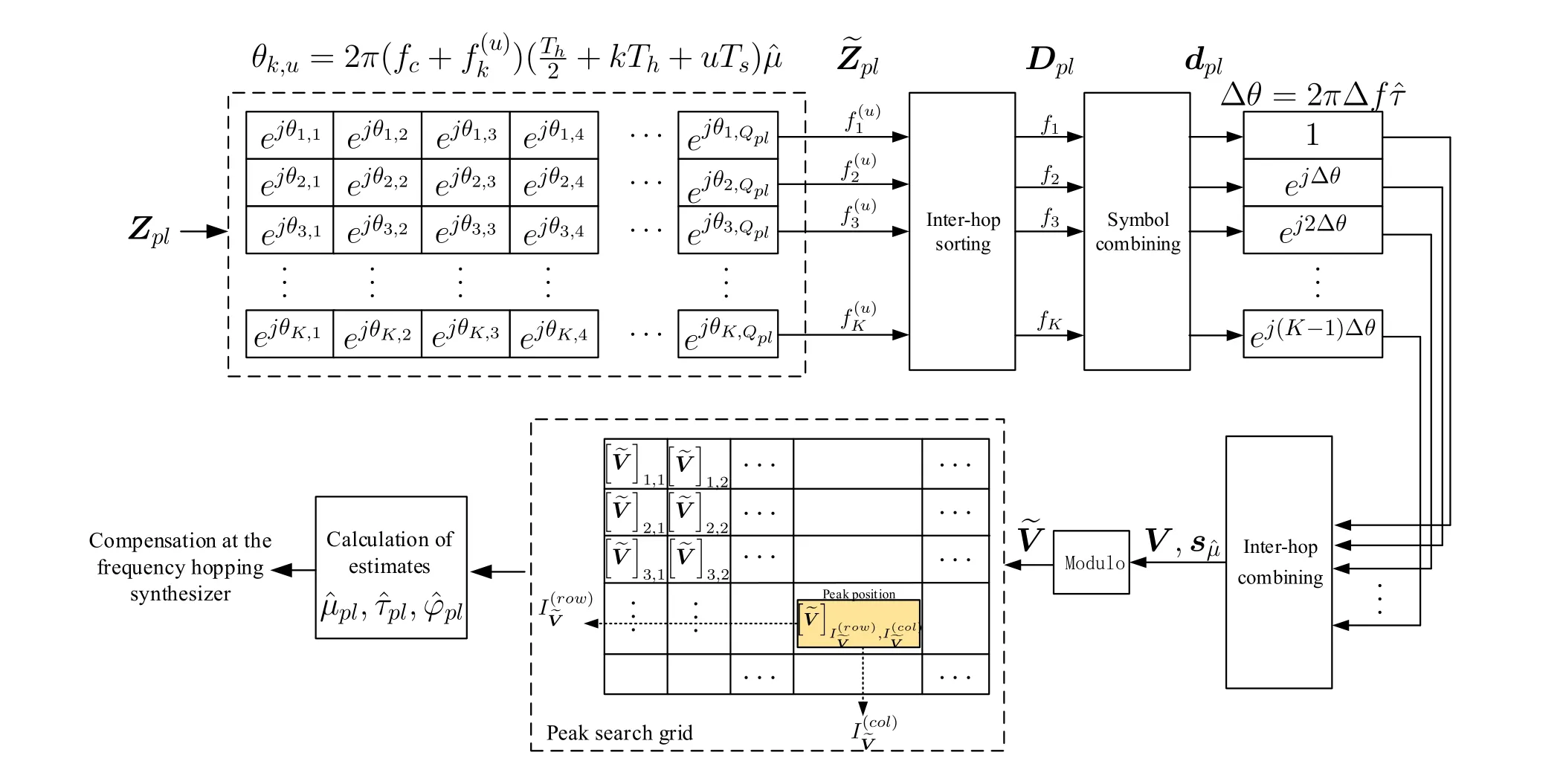
Figure 2.Block diagram of open-loop stage.
Step 1: Phase compensation forZplbased on an initial estimateIn order to perform coherent accumulation,the phase of each element inZplshould be aligned.According to(12),the received phase of each hop is affected byµandτ,and here the compensation is performed forµfirst.
Step 2: Since the actualτis unknown,the accumulation and combining process should be firstly performed in symbol-by-symbol manner and then hop-by-hop.To facilitate the processing,we first sort the intra-symbol hops ofin order of frequency from lowest to highest to obtainDpl∈,i.e.,
By accumulating the rows ofDpl,we can get the symbol-level accumulation resultdpl=.
Step 3: The main object of this step is to compensate the inter-hop phase difference brought by theτ.Since∆fis fixed,after frequency ordering,τwill correspond to the linear changes of the intra-symbol inter-hop phases.Specifically,the phase difference of adjacent elements ofdplis ∆θ=2π∆fτ.With this property,theτcompensation process can be performed using the IFFT.The result of hop-level combining is expressed as
whereFUis theU×UFourier matrix and function fftshift(x) rearranges a Fourier transformxby shifting the zero-frequency component to the center of the vector.0U-Kdenotes the complementary zero to the estimated vectordpl.The compensation range corresponding tois,which covers the error range in (7),and the compensation precision forτis ∆τpl=.
Step 4: Repeat the adjustment of the search parameters in Step 1 to form the search dimension forµ.Update ˆµwith fixed step ∆µpl=,whereNis a predefined parameter that controls the search precision.Theith compensation ofµcan be expressed as
where arctan 2 is the four-quadrant arctangent function.Finally,the results in(20)are fed back to the frequency hopping synthesizer to compensate the time delay,clock skew,and the initial phase.
Next,we investigate the peak shape of the search grid.First,we focus on the dimension ofτ.Assuming the error ofµequal to 0,dplcan be expressed as
wherex=-U/2-1 is theτ-dimension coordinate corresponding toinV.
For the analysis in dimensionµ,similarly,theτdimensional estimation error is assumed to zero.Denoting the coordinate ofinµ-dimension asy=,the phase error ofuth symbolkth hop is
As can be seen from (23) and (24),at the peak ofthe roll-off of bothτandµdimensions is sinc shape and the main lobe widthsand 2N,respectively.Figure 3 shows the results forwithK=32,N=8,U=8K,Qpl=128,Es/N0=10 dB.Define correct detection as the peak onlies in the same grid as the true values ofµandτ.Letanddenote the estimation errors of grid-based search.Then,under the correct detection conditions,the ranges ofandare
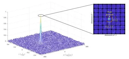
Figure 3.Peak normalized open-loop search grid,K=32,N=8,U=8,Qpl=128,Es/N0=10 dB.
Forφ,since the peak is the result of the coherent accumulation ofQplsymbols,by substitutinginto (24),the range ofat correct detection can be written as
From(25)and(26),it is clear that in order to minimize the estimation errors ofτ,µandφ,NandUmust be selected as large as possible.
IV.CLOSED-LOOP FINE PARAMETER ESTIMATION
In this section,we investigate the closed-loop fine parameter estimation of the residual time delay,clock skew,and continuous tracking of the carrier phase.
Different from Section III,the proposed fine parameter estimation in this section is based on the data segment in stead of pilot sequence.As shown in Figure 4,the proposed algorithm consists of three parts,namely,decoder,PLL and DLL.First,the decoder extracts the log-likelihood ratio(LLR)of the input data to conduct de-polarization through decoding feedback.Then,the PLL performs tracking of the signal carrier phase and the fine estimation of the clock skew.Meanwhile,the DLL performs fine estimation of the time delay.The algorithm works in a iterative form,i.e.,the estimation result of each segment is fed back to the frequency hopping synthesizer to compensate next segment.In addition,a all-one padding sub-segment is attached to the end of each segment to deal with the hardware latency of decoding and feedback processing at the receiver.LetQd=Qc+Qpbe the length of each segment,whereQcdenotes the coded data length andQpdenotes the length of the padded sub-segment.The data segment frame is illustrated in Figure 5.
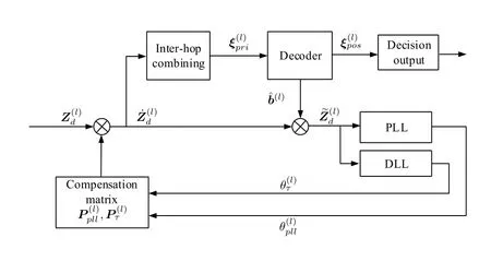
Figure 4.Block diagram of closed-loop fine parameter estimation.

Figure 5.Data segment frame.
Figure 6 shows the structure of the PLL and the DLL.In the proposed PLL,second-order structure is adopted to perform fine estimation of clock skew and the tracking of small jitter.Different from PLL,the DLL in this paper uses a first-order structure to perform time delay estimation since there is no relative motion between the transmitter and receiver.
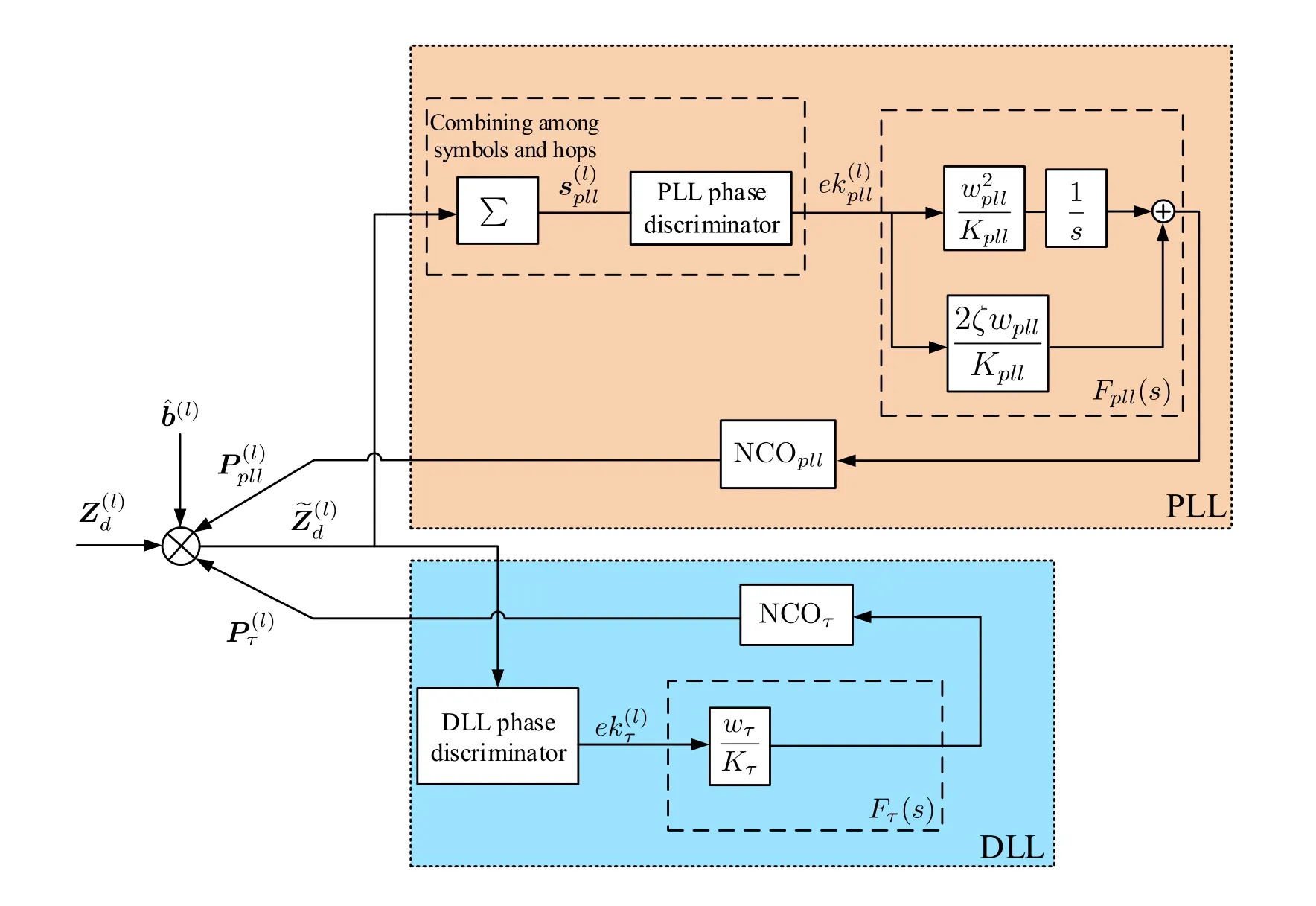
Figure 6.Block diagram of PLL and DLL feedback.
Let the closed-loop fine parameter estimation algorithm input start from the first symbol,then thelth iteration input matrix can be expressed as
As shown in Figure 6,the output of the PLL and the DLL will be fed back to.Denoteandas the compensation output and de-polarization output.Thenandcan be expressed as
4.1 Introduction of PLL Structure
Denoteµd,τd,andφdas the initial errors ofµ,τ,andφ,respectively.Recalling (25),The phase difference induced byµdamong intra-symbol and inter-symbol hops within a segment can be written as
It can be seen thatQdshould be constrained far less thanNQplso that the approximate coherent combining and accumulation can be performed among hops and symbols.In such case,the result of coherent accumulation inQdTscan be expressed as=.The phase discrimination formula of the PLL is
Corresponding to Figure 6,the loop filter for the PLL can be expressed as
whereζis the loop damping factor andwpllis the characteristic frequency.Note that 0.4 <ζ<0.8 is adopted to ensure stable and fast convergence for the second-order system.Kpllis the total gain of PLL.In this paper,both the phase discriminator and the NCOplloutput the normalized result,i.e.Kpll=1.
By the boxcar digital integrator method [32],the analog filter (32) can be mapped to the digital implementation in(33),as shown in Figure 7.
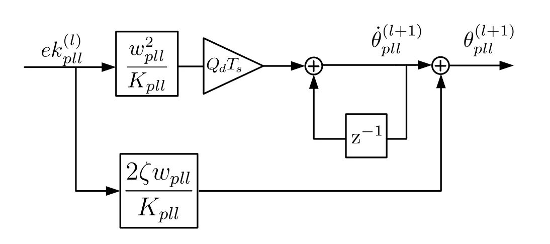
Figure 7.PLL loop filter digital implementation.
The recursive expression for this loop filter can be obtained using the Jaffe-Rechtin filter algorithm[33],which is expressed as
4.2 Introduction of DLL Structure
The basic principle of DLL is to construct early-late discriminator to detect time delay and filter the estimation results in the loop structure.In order to obtain an accurate estimate,the output of the discriminator should respond linearly to the actual time delay within the estimated range.The classical approach is to utilize the code loop and calculate delay by the rolloff character at auto-correlation peak of the code-word[8,28,29].Different from this classical approach,the algorithm described in this section exploit the delayphase characteristics of CFFH,and construct the earlylate discriminator though the phase differences amongKfrequency channels.
For the convenience of description,the principle of DLL phase discrimination is first illustrated by the combination of single symbol.For theuth symbol,the early and late branches are constructed by compensating the phase of each hop according toand,respectively.Denoting the time delay error asτ′=,the normalized compensation results of the two branches can be expressed as
Recalling (25),the residual error of the time delay|τ′|≤,then,|λ|≤≤1.The phase discriminator for a single symbol can be expressed as
It can be seen that by the process of (37) and (38),we obtain a discrimination result linearly related to the time delay.
For thelth iteration,Qdsymbols with different hopping patterns are combined,and the phase discrimination process of the DLL is shown in Figure 8.The early and late branches are designed as
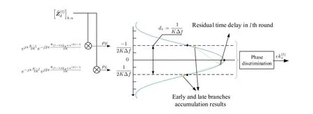
Figure 8.Block diagram of DLL phase discriminator.
The phase discrimination formula of the DLL is
As shown in Figure 8,dτ=is the equivalent spacing between the early and late branches,which corresponds to the correlation early-late spacing in the conventional code loop.dτis inversely proportional to the hopping bandwidth,i.e.,the time resolution of DLL depends on the whole hopping bandwidth.Figure 9 shows the relation between DLL phase discrimination characteristics and the time delay after normalizing to.It can be seen that the discrimination characteristic curve forK≥8 is almost linear within.Note that there are discontinuities in Figure 9 at[-3.5,-2.5,-1.5]/(K∆f)and[1.5,2.5,3.5]/(K∆f).This is because in these cases=0,and denominator in(40)will equal to zero as a consequence.
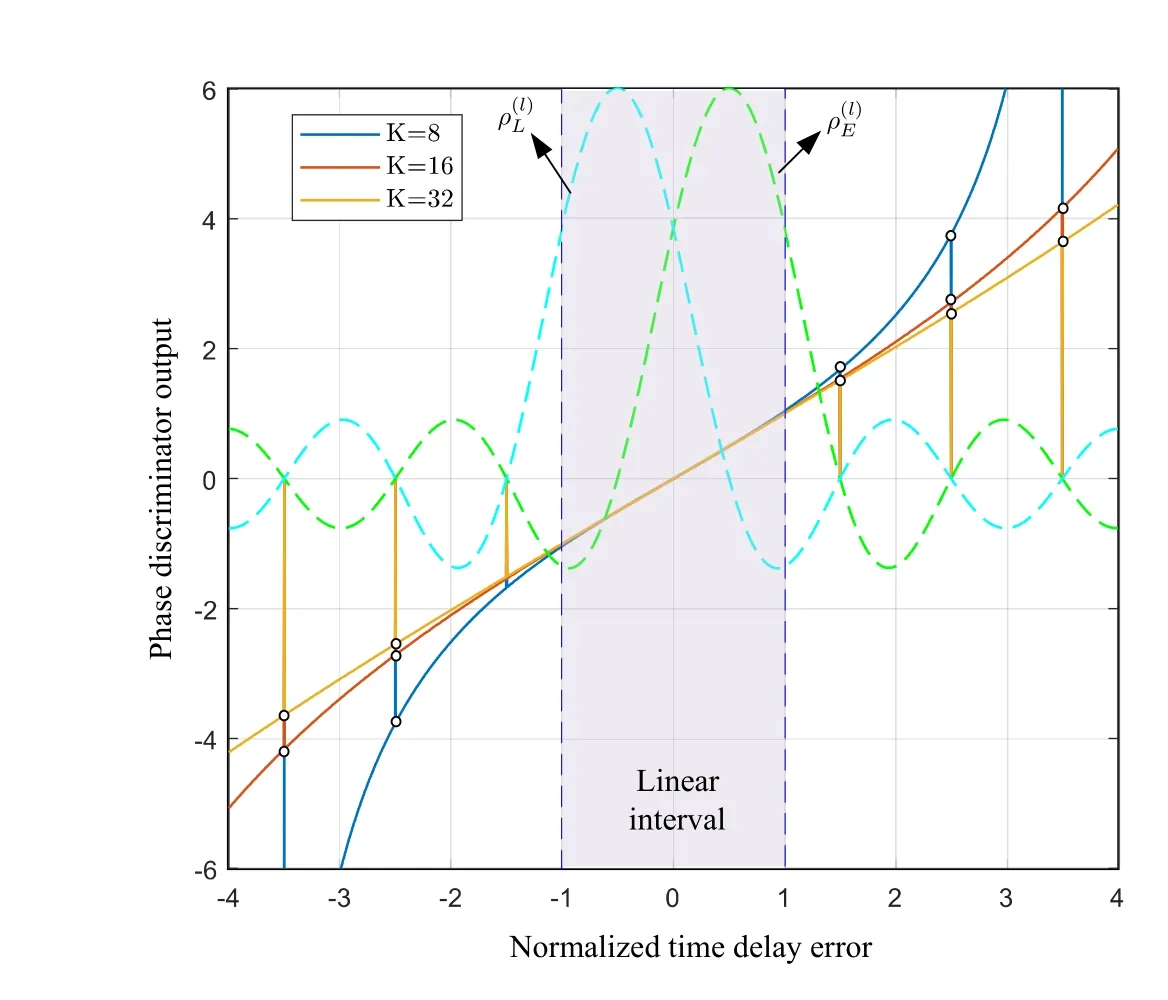
Figure 9.Plot of DLL phase discrimination characteristic.
wherewτis the characteristic frequency andKτis the overall gain of the DLL.Since the output of DLL phase discriminator is the result of normalizing to,we haveKτ=K∆f.
Similar to NCOpll,the work of the NCOτis to transfer the time delay estimation result to compensation matrices.However,since NCOτonly needs to calculate the compensation phase for hops intrasymbol,the structure of it is much simpler compared with NCOpll.Adopting the common first-order integral structure to implement NCOτ,the recursive form can be written as
4.3 Closed-Loop Estimation Error Analysis
In the previous subsections,we have developed the structures and principles of PLL/DLL.Now we investigate the estimators corresponding toµandτin the loop,and derive the RMSE ofφ,µ,andτestimation.
According to[34],aforementioned PLL can be characterized by a linearized equivalent model with additive noise as Figure 10.anddenote the phase of input signal,the phase feedback adjustment,and the tracking error,respectively.is a zero-mean Gaussian noise and its power spectral density normalized to the signal power is[34],whereandApllare respectively the double-side noise power spectral density and the amplitude of PLL inputs.Considering the integral property of NCOpllin(35) and (36),the transfer function corresponding to NCOpllis equivalent to.The system function of the PLL equivalent model can be expressed as
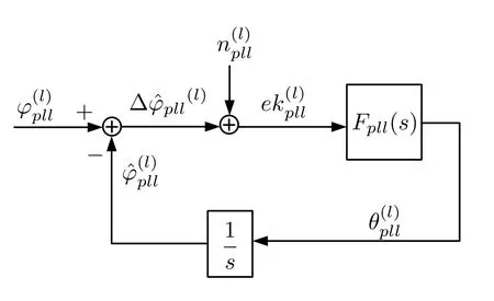
Figure 10.Equivalent model of PLL.
Substitutings=j2πfinto (43),the equivalent noise bandwidthBpll(half-side bandwidth)can be expressed as
whereQdTsis the normalization coefficient.In the steady state,the error ofcan be regarded as the transient integration ofand the variance of the phase erroris equal to the variance ofThe variance ofis given by
Note that the equivalent model input is the combining result withinQdTs,we have
whereEsdenotes the symbol-level energy.By substituting(46)into(45),the RMSE ofcan be written as
As can be seen from(35)and(36),the output of the loop filtercorresponds to a frequency adjustment coefficient of input signal.From this perspective,can be regarded as an estimate forµ.In the steady state,the estimate ofµis expressed as
According to the form ofFpll(s),by ignoring the correlation of the noise in the loop,the variance ofin the steady state is approximately expressed as
By (48) and (49),the RMSE ofafter normalizing toQdTscan be approximated as
For the estimation of time delay,is the filtered result of the DLL and can be directly used as an estimate ofτ.To derive the RMSE,we first analyze the single-symbol case as with in the Section 4.2.In the presence of error noise,according to (38),the phase discrimination function of theuth symbol is expressed as
wherenEandnLare the noises introduced by the early and late branches,respectively.Denotenτas the noise vector corresponding to theuth symbol,nEandnLcan be expressed as
whereντ=and conj(·)represents the conjugate function.Note thatwhenKis sufficiently large.Therefore,nEandnLobey the independent zero-mean Gaussian distribution with variance var(nE)=var(nL)=.Aτdenotes the hop-level signal amplitude of theuth symbol reception vector.Furthermore,letw1=ℜ[nE-nL]andw2=ℜ[nE+nL],thenw1andw2obey the i.i.d.Gaussian distributions with variance var(wE)=var(wL)=.In the steady state,the actual residual errorλin(37)is very small.Substituting(37)into(51)and taking an approximation,we can get
With above analysis of the PLL,an equivalent linearized model with additive noise for the DLL can be made as shown in Figure 11.The equivalent noisecorresponds toℜin(55).The system function of the equivalent model in Figure 11 is
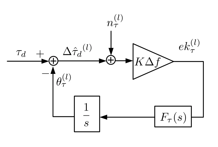
Figure 11.Equivalent model of DLL.
The equivalent noise bandwidthBτcan be expressed as
Similar to the derivation process of (47),the single symbol RMSE ofin the steady state can be obtained as
4.4 Decoder and Decoding Feedback
In the previous discussions about PLL/DLL,it is assumed.However,since information is mapped in the data segment,the symbols inb(l)must be interleaved with+1 and-1.In order to obtain the expectation of input symbols,the posterior LLR informationof the coded sequence should be calculated.Note that the code-type should be carefully selected so that the decoding LLR corresponds to the encoded sequence,such as Turbo,LDPC.
Considering the approximate ideal parameter compensation,the a posterior probability (APP) of the coded symbolsin thelth iteration is[37]
Assuming that each codeword has equal probability at the transmitter,thensatisfies
whereB⊂{1,-1}Qcis the code space,and function card(A) yields the cardinality of setA.By performing hop-level combining on the coded symbols inthe soft information input into the decoder can be expressed as
For theuth coded symbol in thelth iteration,the posterior LLR information can be expressed as
Substituting
into(63),the posterior expectation of theuth symbol in thelth iteration is
where tanh(x)=is a hyperbolic tangent function.Further,usingas an estimate offor feedback,(29)can be rewritten as
V.CRLB OF PARAMETER ESTIMATION
In order to evaluate the performance of the proposed algorithm,we derive the CRLB ofµ,τ,andφin this section.The derivation process is based on the signal model of the open-loop stage in Section III.
Substitute the terms in the(12)with
According to(10),the mean of the reception vectorzplis the signal termrpl=Aτ,µ,φg.Its covariance matrix can be expressed as
Let the vector of parameters to be estimated be
The Fisher information matrix (FIM) [38] can be expressed as
Sinceθis independent of Γ,the second term on the right of the equation in(69)is 0,then
Using the chain rule to expand the partial derivative term in(70),it is derived that
By substituting(66)and(71)into(70),we have
By combining (70),(72) and (73),the estimation CRLB ofµ,τ,φcan be derived from the corresponding diagonal elements of the inverse matrix of FIM[38]as
VI.SIMULATIONS AND DISCUSSIONS
In this section,simulation results are provided to illustrate the performance of the proposed algorithms.Suppose the normalized symbol rateRs=1 sps.Without loss of generality,we set the center frequency of the received signal tofc=107Rs.K=32 andM=8 are adopted in simulation,respectively,and thus,the frequency space ∆f=MKRs=256Rs.In addition,it should be noting that the CRLB in the following figures correspond to the RMSE results of the estimation.
For the open-loop stage,the length of the pilot sequence is set toQpl=2048.To show the impact of different search intervals ofµandτ,the parameters are selected asN∈{16,32},U∈{512,1024}.Particularly,whenN=16 andU=512,the true values ofµandτare assumed to traverse the search range in steps ofand,which means that 104test points for each search grid.For all the simulations,1000 times of Monte Carlo simulation are performed for each test point.
Figure 12 demonstrates the correct detection probability of the grid-based open-loop search algorithm.It is clear that the correct detection probability of open-loop search varies with search parameters.For the same SNR,the detection probability is the highest in the case ofN=16,U=512 and lowest in the case ofN=32,U=1024.The two cases ofN=16,U=1024 andN=32,U=512 have almost the same correct detection probability.The main reasons are as follows,firstly,the detection becomes more sensitive to noise as the search grid tends to be denser with the gap between the mean values of adjacent grid points getting smaller;secondly,the peak shape is sinc roll-off in both search dimensions ofµandτfor positions close to the true value.Therefore,keeping the search precision of one dimension unchanged but increasing that of the other dimension by the same proportion results in approximately the same effect on the overall detection performance.
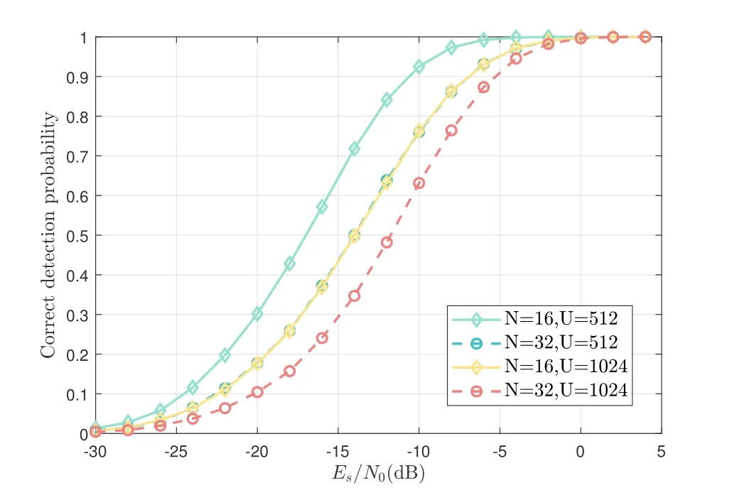
Figure 12.Correct detection probability of open-loop search.
Figure 13 shows the RMSE ofµ,τ,andφunder correct detection.It can be seen that the RMSE ofµandφare only sensitive toN,while the RMSE ofτis only sensitive toU.This corresponds to the results in (25) and (26).It is worthy noting that the RMSE curves ofµ,τ,andφtend to be flat at high SNR,and the gap with CRLB increases.This is because of the discrete nature of grid-based search.When the true value of the parameter is not aligned with the points of the search grid,the peak will appear on the point closest to the true value with high SNR.As a result,the increase in SNR at this point will not reduce the error.Taking theµ-dimension search as an example,when the SNR is high,neglecting the effect of noise,the true values lying within the interval ofapart from a specific grid pointpµwill be treated aspµ.The simulation RMSE result can be approximated as
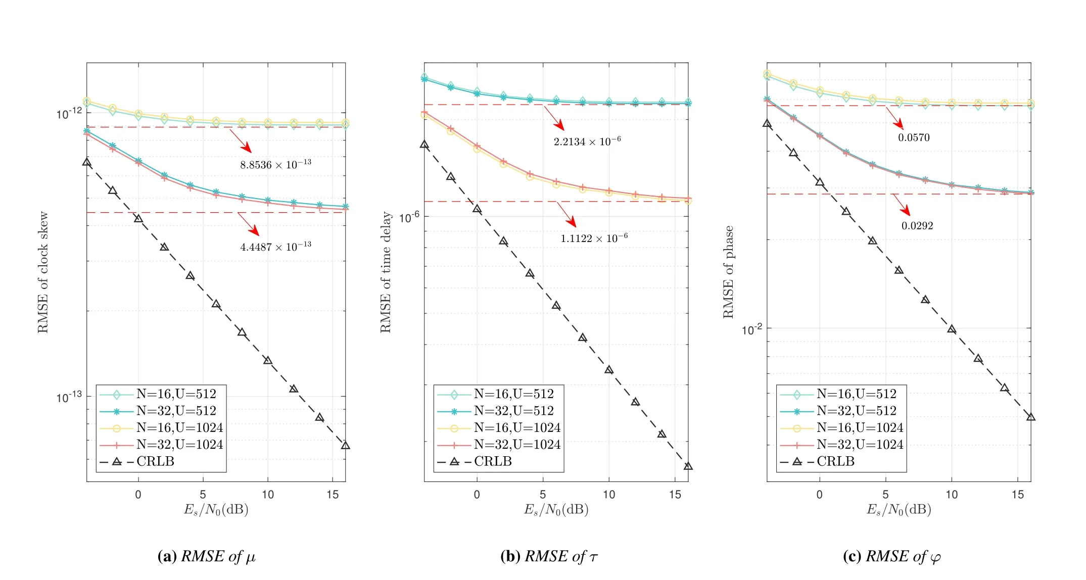
Figure 13.RMSE of grid-based open-loop search.
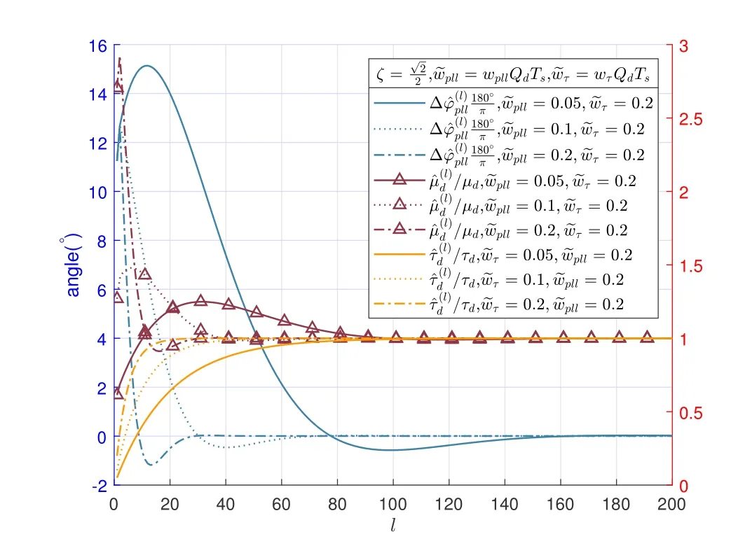
Figure 14.Plot of iteration convergence.
The red dotted lines in Figure 13 demonstrates the results of substituting the simulation parameters into(75)and(76).
For the closed-loop stage,the LDPC code with code rateand code lengthQc=128 is adopted.On this condition,the relationship between the bit-level SNR and the symbol-level SNR is [Eb/N0]dB≈[Es/N0]dB+3 dB.The length of the padding sub-segment isQp=2,i.e.,the length of one segment isQd=Qc+Qp=130.We assume that the errors of parameter input to the closedloop algorithm correspond to the maximum residual of grid-based open-loop search stage.SubstitutingN=16,U=16Kinto(25)and(26)yields the residual error.
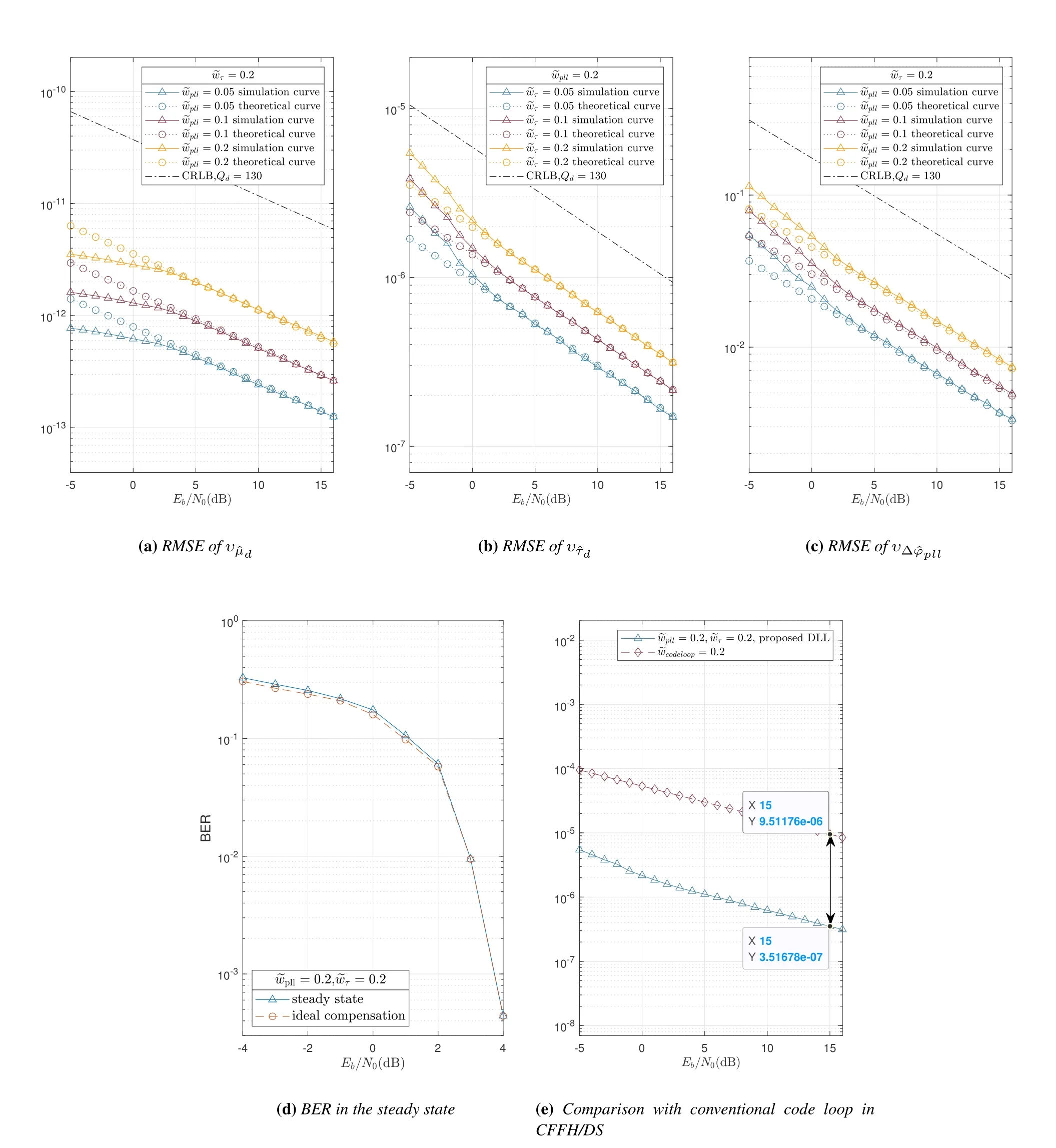
Figure 15.Closed-loop simulation results.
Figure 15(e) compares the time delay estimation RMSE of the proposed algorithm and the code loop algorithm of CFFH/DS system in [14].Considering the fair comparison,the CFFH/DS system is set to the same symbol rate,order of loop,and length of accumulation time in the present simulation.In addition,the CFFH/DS system adopts symbol-by-symbol coherent integration in the simulation.As can be seen,for the same normalized characteristic frequency,the RMSE results of proposed algorithm is significantly lower than that of the code loop algorithm within a wide SNR interval.By comparing the simulation results,the RMSE estimated by the proposed algorithm is only aboutof the code loop algorithm atEb/N0=15 dB.
VII.CONCLUSION
In this paper,we proposed a novel fine synchronization algorithm for CFFH systems.The algorithm first locks the parameter errors within a small range by the gridbased open-loop search process,followed by further precise estimation of the parameters using the closedloop estimation method.This paper presented a detailed implementation structure for each stage and analyzed the error of the estimates.In addition,this paper derived the RMSE of estimate of time delay,clock skew,and carrier phase in closed-loop stage,as well as the CRLB.The simulation results showed that the system can achieve good tracking of the clock skew and carrier phase,while the time delay estimation has a significant improvement compared to the conventional code loop algorithm.
ACKNOWLEDGEMENT
This research was funded by National Scientific Foundation of China under grants (No.62101050 and No.62001022).
杂志排行
China Communications的其它文章
- Learning-Based Dynamic Connectivity Maintenance for UAV-Assisted D2D Multicast Communication
- AIGC Scenario Analysis and Research on Technology Roadmap of Internet Industry Application
- Dynamic Visible Light Positioning Based on Enhanced Visual Target Tracking
- Ultra Dense Satellite-Enabled 6G Networks: Resource Optimization and Interference Management
- Analysis and Optimization of Validation Procedure in Blockchain-Enhanced Wireless Resource Sharing and Transactions
- Anti-Jamming and Anti-Eavesdropping in A2G Communication System with Jittering UAV
